Control power supply 405 IPS by Labview
Hi all
I need to configure a 405 FPS of power Iso-tech and controll it via a LabVIEW code.
Can I use NI-VISA to control this power via RS - 232?
I looked everywhere but could not find the LabView drivers for this power supply.
Can I ask you what to do? A bit of luck on the way to generate a Power Supply Labview driver custom? or VISA can help control power supplies? but I still need to find the driver for food? What can I do if no driver is available?
Thanks in advance for your help.
Best regards
Serge
Hello
Thanks for reminding me.
It comes in 2011 to LV and I used a model of power dc to start.
I adapted only Initialize.vi and set up output.vi and you need to test only those.
I have briefed the correct settings of series.
Place it in instr.lib
I would really like to see the State, but it is not a detailed instrument.
Tags: NI Hardware
Similar Questions
-
Control via RS232 interface labview DC power supply
Hello world!
I'm new to labview and I'm trying to control a DC power supply using a serial RS-232 (output voltage). I can't use an interface Gbspecifications TO have only a single module that is used for another task. Any advice on how to go about it in labview?
Thank you very much!
Find the driver for your device here: http://sine.ni.com/apps/utf8/niid_web_display.download_page?p_id_guid=510F94BB50256F51E0440003BA7CCD...
It will work for GPIB or series with VISA.
-
A non programmable power supply with LabVIEW + additional programming hardware
My company is interested in the use of LabVIEW to automate a non programmable DC power supply. The instrument in question is the U8001A device, but the idea must be the same, regardless of the manufacturer (the instrument was purchased while I was hired, or I would have opted for one with SCPI commands if that's a thing for power supplies):
http://www.Tequipment.NET/AgilentU8001A.ASP?source=googleshopping&gclid=CMn-rPzAks0CFZM6gQodMu4McQ
We have two connectors that would be plugged into the power supply and in the 'brick' that holds some sample we want to warm up. This has worked well for our initial target, but we are now interested in time these events alongside 1-2 other instruments that we are exploited (for example a-ohmmeter for quality control), where we can control all this through LabVIEW. Say, only allowing the power reaching the sample at intervals of 5 seconds, with widths of 1-2 seconds impulse.
I'm sure I'll need a multifunction data acquisition device, and I already have my eyes fixed on the purchase of the NI USB-6501 (link below). My main question is about any additional material which is necesasry, if only a debate of ideas cenceptual on what I'm trying to accomplish. I can do everything I plan only through the acquisition of data, or are there other necessary materials, such as doors? What type of material is suitable for it? I apologize if this is the wrong sub-forum for this topic, as seems to be the subforum of material more appropriate upon publication. Thanks for your time!
http://sine.NI.com/NIPs/CDs/view/p/lang/en/NID/201630
Not even an analog command on this power supply... Range of tension and how much power do you need? You may be able to make an operational amplifier circuit, but find out who can handle that many likely power won't be easy.
Honestly, I say just to bite the bullet and get a programmable power supply. It will be cheaper as you try to make a personalized tour to adapt to a peg in a hole square circle.
-
Connection of agilent E3631A DC power supply to the computer via a RS 232 for labview
Im trying to access the computer via a cable RS 232 for sully power DC E3631A agilent use labview to operate the instrument. But the instrument is now detected by the computer and when I check instruments instruments connected tools-tool-find, told me no device not connected. I tried to use max by changing the configurations, but so far it doesn't work anymore. Please can someone tell me what to do
I don't know if MAX is the instruments of automatic detection on the serial port. You can contact the instrument using Hyperterminal or something like that? Also make sure you serial port settings are all correct (it is the most common reason).
-
How to control the TTi QL564P Power Supply with USB connection?
Hello
When I connect the TTi QL564P power supply via the USB port I see not on MAX (peripherals and interfaces) the virtual serial connection. With GPIB, everything works great!
I already downloaded the latest drivers on the site of the IFG.
And I created a simple VI like this:
OPEN--> VISA VISA WRITE ('V1?") --> DELAY (0.1 s)--> READING of VISA--> VISA CLOSE
(works via GPIB, does not work via USB)
VISA OPEN I have the name of resource VISA only the LPT1 and COM1 ports available... so where is the USB port (this virtual serial port, case)?
VISA GPIB resource name is the ALIAS that I set on MAX...
Thanks for the help

OK, the solution was... on the front panel of the power supply, I replace the USB bus (I had default GPIB
 )
) -
Table 3646 power supply problem
Hello
I can't get power table 3646A to update the voltage continuously with output trigger toggle, I looked at the Vi provided by this site but, the program works as a time control. My goal is to hang the PS with a PID loop at a temperature controlled heating, so I need to vary the tension of a sensor-based and updated updated according to the needs. Is there a way to bypass the output to toggle control or is it a separate labview program that can change settings on the fly rather than the start and stop.
Thank you very much!!
The reason that he died, it is that you tell it to do. Look at what your program does: it initializes the power. Initialization sends a command 82 h with the data value 02. This sets the power to command with the output OFF remotely! Then activate you the output. Then, you set the voltage to the desired value. Immediately after, the while loop iterates and the power comes back again.
1. do not place a while loop to run forever. Do not use the button abandon in the toolbar to stop your VI. It's an escape for use during development hatch, where a program does not run correctly. Put a stop button on your façade and also use stop the loop.
2. do not use seqeuence structures if not necessary. Your program will work exactly in the same without it. LabVIEW uses data streams to determine which part of the program will then run.
3. you should learn about state machines. They give you a lot of flexibility to do this kind of things you are trying to do.
4. until you learned how to use a state machine, move the initialization and activate spuuly screws outside the loop. They should only run once. Put configure VI it inside the loop. Also put a wait function (ms) inside the loop. The loop doesn't have to try to run hundreds or thousands of times per second. (A better approach would be to use a structure of the event and send new data to power thepwer when the value of the voltage level is changed).
5. once the set loop a Power Supply VI activate with defined entry to disable the output, followed by a close VI. This is similar to the sample program.
Lynn
-
Hello
We need to develop a new power supply Tester in LabVIEW software. We currently use the software LabVIEW 8.6 for our tester and we want to redraw the whole algorithm. What Version of labVIEW is better suited for this purpose right now? We also want to include a report generation tool and PXI. It would be useful if someone call tell me cost as well.
Thank you
prvtmg
Using PXI implies the new test equipment. PXI is a completely new platform.
Personally, I don't see much need to report generation tool, but if you see that it had to directly manipulate word or excel, it would save you time.
Any version, even your current is perfectly capable of controlling instruments. If you plan the upgrade, might as well get later.
-
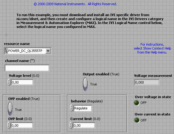
Problems with the DC Power supply QL 355TP: I can not set the tension level
Hello
I'm trying to control a power supply DC via GPIB. The power supply being used is the QL355TP of society Thurlby Thandar Instruments (TTi). There are no drivers of OR to control the instruments, then I need to download and install the driver from the website of TTi: the package I installed is as follows:
"QL - P power supplies, (including QL Series II) series pilot National instruments (Labview and CVI)"
and I also installed the following:
"QL - P power supplies (including QL Series II) series, IVI driver"
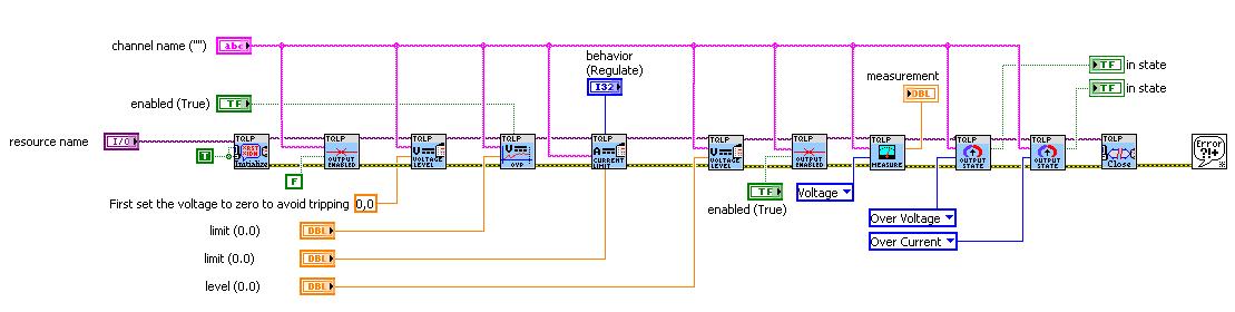
So, my problem is that when I try to use the sample application of the driver 'Volts.vi DC Ouput'; defines a specific level voltage, does not work properly. The application gives no error, but it is not set the specific level voltage. However, other functions work properly, as the measure or activate the output. I tried a lot of things, but I don't know why it does not work.
I enclose the block diagram of the application and the front panel:
I must say that I barely control instruments using Labview and is possible that this problem would be because I did not consider things basic and mandatory.
Any help is appreciated.
Thank you.
p.s. Try to replace the decimal comma to period. It is possible that the driver does not correctly handle the comma.
-
Power supply hangs after running vi second time
Hello
I'm just starting my adventures in worlds of LabView and I encountered a problem with my first serious vi which is control CPX400DP power and oscyloscope DPO4104.What my vi should do:
Firstly, it defines two supply channels current levels (5V on the first, 0V on the second, etc.) and the size of the jump (0, 5V for example). Then vi must change two levels depending on the size of the jump, and repeat until the current levels of the two channels would be opposite to the starting value (in this case, 0V on the first channel, 5V on the second). Also before every current change the vi would save to the file average measurements out of oscyloscope waveforms.
What does my vi:
In the first round, it seems he does everything in order (with resonable numbers a new text file is created). However, when I try to run the vi again my power supply freezes short after some changes underway. I can't stop the execution of the vi in LabView (it takes a while though), but to run the vi successfully, once again I have to reset my power (turn it works).
I tried to work around this problem by modyfing the vi in such a way that he would do what I want several times during the running vi only once, but unfortunately that did not work.
If someone would have any suggestions on what I am doing wrong or how to help solve this problem do not hesitate to share I don't bite... much
 , but seriously, I'm stuck with this problem for over a week and I will be happy to advice
Thank you!
Waldek.
PS Sorry if I'm not clear somewhere but I'm not used to talk about programming in English

PSS as attachments are my main vi and two sub live.Revan-Ghost wrote:
Thanks to a suggestion from Bill, but could you elaborate a little bit on "try to insert; * MUTUAL FUND? After each setup command "? I understand what would make, concept wise, but as a new user, I don't know how to do this in LabView. And good Uncle Google says nothing about '; * MUTUAL FUND? "and insist to talk instead of OPC servers.
I'm sorry - I looked at the manual and could not realize that the subVIs missing from your code actually were drivers for your diet, so you will not be able to implement this (unless the pilots themselves have the ability to 'Operation Complete' - I hope the drivers provided with the documentation). Otherwise, you may be stuck having to hardcode waiting after each command.
If you have written your own drivers, it's how send you the command set output 1 to 1 Volt:
V1 1; * MUTUAL FUND?
The V1 1 sets your voltage of 1 Volt. To turn to another command, use the semicolon. The * OPC? forces command him back send a '1 '. As orders are followed in order, food cannot send the '1' until he gets treated the command set to 1 Volt. When this command is complete, the '1' is sent, you read the 1 out of the buffer and move. This avoids problems where you stack on too many commands at once. I checked the manual and it supports this feature.
-
HP pavilion a1710n power supply needs replacement.
I have an old HP Pavilion a1710n desktop power supply crashed and burned and needs to be replaced. I've never been on a power supply on this computer before I upgraded memory and dial-up fans in the past.
I already ran through the list control to full power on this site to confirm that it is food that is broken and needs replacement and no cord or anything else.
I also confirmed what power to order part. At this point, I just need to see a video of step by step on how to replace the power supply inside the computer tower or read the good strong guidelines for how to do it.
Some advice there?
Thank you
It doesn't seem to be a video on the site of HP but it is an easy process.
(1) turn off your computer and disconnect the power supply. Remove the power cord from the power outlet.
(2) open the casing and place the computer on its side (open side upward).
(3) take pictures where going to each power cable.
(4) disconnect all power connections.
(5) remove the four screws on the back of the housing supply by keeping in place.
(6) turn the power off (can be a "locking tab" now in place.
(7) reverse the steps to install your new power supply.
Refer to photos for the location of the place where to reconnect the power cables.
-
Power supply N6700B Low Profile pilot backward compatibility
Hello
I've recently updated the instrument for the Agilent N6700B Low Profile Power Supply drivers on my system. I run LabView 8.2.1. For some reason, the new LabView VIs have all their VISA Instrument inputs and outputs incompatible with my previous thread and definitions of port at the top level VI. We don't know yet what exactly is different, but I need to remove the wire and the port at the top level VI and re-create it. Do this for all my screws where this driver is used is very tedious... Is this really a compatibility problem, and this is known? No work around available?
Unfortunately, I do not know what was the previous version of the driver N6700 overall.
One thing I noticed and found strange: on a separate system where the pilot works fine (which I assume is the old driver), the pilot of VI property indicates the revision number is 104. On the newly updated system, the same driver VI property indicates that the revision number is 16. Does this mean my update failed?
Thank you
Benoit
It was the source of the problem. I reinstalled the VISA type instead, and not everything works perfectly.
Thank you!
Benoit
-
E364xa power supply screen is frozen when you are working in remote mode.
I use the sample E364Xa screw, which was downloaded with the driver (.dll) of the Web site OR. Power supply screen freezes when a "RMT" sign appears on the screen. Is anyone konow how to solve this problem?
When in remoote mode, you must go back in local mode to use the controls on the front panel, just like any other instrument. From the Manual:
When the power is in remote mode, you can return to the front operating mode at any time by pressing the key (Local) If you don't have not previously sent the locking of the front panel control. A change between the façade and the modes of remote operation will not change in the output parameters.
-AK2DM
-
2 power supply: voltage increment on one when the current research on the other?
OK, so I work with 2 power supplies E364X Agilent. I have a unit with a door and drain that I do apply power. With the door I am applying 1.5V & .3a current limit, the drain I do a request 9.5V & 1 has current limit. What I'm trying to do, is to increase the tension of the door while controlling the current Drain and have the increments to stop when the Drain current comes down to .5A +/-50mA. I guess I kind of two questions. I use a state machine, the first iteratino defines the PS for the desired parameters (works fine), the next two iteration is supposed to accelerate the Power Supply Gate Voltate with small increments, check the current reading of power drains to see if it falls in the interval given, otherwise the increase continue, check again and so on... I'm having a problem with the part of increment as well as checking for the current game. I was thinking maybe I need to use a flat sequence or something along that line. Any help would greatly be apprecaited
For #1 supply, you should just have the voltage itself inside the loop. It would probably not hurt thanks to additional error checking just in case (you can then give up if there is an error). The rest can probably not stay outside the loop.
-
Hello
Windows OS 8.1
Power supply 420
I wanted to upgrede my diet to something more powerful. I was wonder if I could improve my diet and how to do it.
WhiteAssassin74, welcome to the forum.
Yes, this is a very good power supply (PSU) made by Corsair. I suggest you read the presentation on the page. He says that the HX Series features a thermally controlled fan. It runs only when the heat makes it necessary. It's also modular, which means that simply use the required cables. This makes better air circulation.
Before you buy any power supply, you must measure the existing PSU and compare the measurements with the one you choose.
Please click on the Thumbs up button '+' if I helped you and click on "Accept as Solution" If your problem is resolved.
-
Creating a power supply Variable myDaq
Hello world
Just got my myDaq NOR the other day and just start playing with it.
I was a little disappointed to know that power supplies were not Variable (i.e. fixed 5V and +/-15V), but that's what I have for not reading the fine print
.I thought a Variable power supply would be a good pleasure first of all of the project, but have no idea where to start. I was hoping that you guys could give me some advice/point me in the direction to look.
I intend to use myDaq for mainly breadboarding for laboratories after EE.
Since the 5V power allows for the most recent shooting, I think it would be the first supply to build.
Can someone point me in the direction to move forward?
Thank you!
-Ernie
Hello Ernie,.
Function of the desired output voltage and and currently, there are a few approaches you can try.
Buffered outputs analog is the easiest method. You could probably get to +/-12V if you choose a small enough margin requirements with op amp and add 20% gain. You would use the +/-15V rails to power op amp (don't forget to consider the tolerance of rail), and you should limit your output to 32 spec my the +/-15v rail. The buffer is essentially a linear regulator, so be careful of the power dissipation of the amplifier at high currents.
Output currents higher with lower voltages, consider using a switching regulator. There are a variety of topologies based on the input-output voltages. Look for Buck to withdraw to an input voltage higher than a lower output voltage; Boost to intensify; Buck-Boost to step upwards or downwards. There are others, but these are simpler to start. You can use the outputs analog of the myDAQ to inject a voltage error in the feedback from the regulator to allow programmatic output voltage control. Take a look at sellers sites power supply chip (TI, Analog Devices, Linear Tech, National Semiconductor, etc.) for application notes and recommendations from component.
Another approach is regulatory digital switch command. These provide a detailed and read back functionality via a digital interface to the chip. Google "digital power" for ideas.
If you need more power, you will need to provide an external power supply or battery, but control could still come from the AO myDAQ or digital interface.
It can be a difficult exercise, but I hope this help to get you started.
Charles Y.
Maybe you are looking for
-
Will it work if I put a 256 MB ram on Satellite 2515?
Will it work if I put a 256 MB ram on Satellite 2515?
-
Find file more recent directory and delete after 10 files
Hello I want to create a vi that can do two things 1 entry: 1. 2 directory. Number 2. output: new file in the directory specified 3. delete all the old files if the number is two, so if the number = 2 then only keep two new files in the directory and
-
IE 7 won't
-
Uninstall of Microsoft Virtual PC
How to uninstall Microsoft Virtual PC. It does not appear in the list of programs to uninstall. I want to make sure that I get everything.
-
After the crash of my mac, I'm PC
After the crash of my mac (HS) I under of went P, but I have not disabled the license installed on the mac photoshop.Today I need install photoshop (CS6 for MAC version in the format box with serial number photoshop RET).Is this possible and how?Than