Control via RS232 interface labview DC power supply
Hello world!
I'm new to labview and I'm trying to control a DC power supply using a serial RS-232 (output voltage). I can't use an interface Gbspecifications TO have only a single module that is used for another task. Any advice on how to go about it in labview?
Thank you very much!
Find the driver for your device here: http://sine.ni.com/apps/utf8/niid_web_display.download_page?p_id_guid=510F94BB50256F51E0440003BA7CCD...
It will work for GPIB or series with VISA.
Tags: NI Hardware
Similar Questions
-
Hello!
I use dasylab to a small control. I would like to controll 3 adjustable transformers. The pc with the NI USB-6210 is near the transformer. Via RS232 I want to controll the processors of the control room. I have connected the two stand-alone (one near the processor) and the other in the control room with a cable RS232. Is it possible to use input RS232 dasylab for this effect? I'm just at the beginning of this project, and I appreciate all the information and advice you can give.
Thank you very much and have a nice day
Hilby
For the RS232 string... we expect that the string must be delimited - for example, it ends with a
. When you use the notation $1
DASYLab will begin at the current location and put all the characters in the global chain number 1 (${STR_1} in other modules) until the \r (the
character). It does not put the delimited in the global chain. If you use the store in the chain, then catch it all on the line. If you need to anchor it better, use the string in quotes to search for a unique header before the $1
"Single text" $1
will interpret this line
Single text can be stored in the global chain
and store 'can be stored in the global chain' in the global chain 1. She anchors on the 'Unique' text and ends at the
. For relaxation... use the pre/Post trigger... it's more reliable and outputs 0 or 5.
-
How to send power QL355P control via GPIB in labview
Hello
I use QL355P power, DUT and usbCAN part 3.
I want to send OFF switch power control / IT for my DUT under will restart, using labview.
I have no no on hoe to send commands gpib in labview
is that all can help me?
Let's focus on the other thread, as indicated by Ravens Fan. Please post here instead of here.
-
Control of Genesys power supply
Hi all
I need to configure a power of Genesys (GEN 3.3kW GEN8-400 series) and control via a code LabVIEW.
I also have an old code that already does this task, however it was written with an older version of LabVIEW
LabVIEW 2010 needs drivers for food, but when I tried to run the old GUI.exe GEN series I found it does not work. It says that I need LabVIEW 6.1 runtime, but now that I've updated my LabVIEW I have a newer version of the LabVIEW RunTime.
Since the people who has developed such a code is no longer available, I need to reconfigure the power from the beginning.
Can I ask you what to do? I also tried to find a guide on NI.com site but I wasn't able to find anything related to this subject, certainly because I don't know how to do a search on this topic.
Thanks in advance for your help.
Best regards
Marco
-
Control power supply 405 IPS by Labview
Hi all
I need to configure a 405 FPS of power Iso-tech and controll it via a LabVIEW code.
Can I use NI-VISA to control this power via RS - 232?
I looked everywhere but could not find the LabView drivers for this power supply.Can I ask you what to do? A bit of luck on the way to generate a Power Supply Labview driver custom? or VISA can help control power supplies? but I still need to find the driver for food? What can I do if no driver is available?
Thanks in advance for your help.
Best regards
SergeHello
Thanks for reminding me.
It comes in 2011 to LV and I used a model of power dc to start.
I adapted only Initialize.vi and set up output.vi and you need to test only those.
I have briefed the correct settings of series.
Place it in instr.lib
I would really like to see the State, but it is not a detailed instrument.
-
Reading from the sensor to LabView via rs232 or Subvi problem
I'm quite new to LabView and not too experienced with instrument control so I was wondering if someone could help me to solve my problem?
Currently, I'm using LabView 2011 and I'm trying to read pressure DualGauge of Pfeiffer (TPG 262) pressure sensor and display the readings of two pressure on LabView. However, when I run my program, the pressure readings are not displayed - what is displayed are default 0.00 if same mBar pressure reading a reading of the display of the DualGauge probe. To connect the sensor, I use a RS232 cable and have managed to find the device on my device manager, so I don't think that the connection is the problem (I've also seen the port appears in the Device Manager, when I connected the sensor via RS232 and USB in my computer). I also use Subvi Pfeiffer in my code, and I suspect that the problem may be in there.
Attached is my code and here are links to the manual of the DualGauge and the driver of the software LabView of Pfeiffer
Double manual gauge - p. 23 and 68 are probably the only things related to the RS232 connection.
http://www.idealvac.com/files/brochures/Pfeiffer_TPG262_Operating_Instructions.PDF
DualGauge LabView driver - software Pfeiffer double gauge LabView driver 2009
Any help is very appreciated!
-Candice
You have not tested really do anything. Devices and MAX Manager displays only the com port that you added to the computer. It does nothing to verify that an instrument is truly connected. You might have the wrong settings of com or the wrong type of cable serial (null-modem is required). I suggest that you start with program such as hyperterminal, PuTTY or MAX and try something simple. It seems that you will receive an acknowledgement returned by the instrument when a correct command is received. Make sure that this simple step that happens.
-
A non programmable power supply with LabVIEW + additional programming hardware
My company is interested in the use of LabVIEW to automate a non programmable DC power supply. The instrument in question is the U8001A device, but the idea must be the same, regardless of the manufacturer (the instrument was purchased while I was hired, or I would have opted for one with SCPI commands if that's a thing for power supplies):
http://www.Tequipment.NET/AgilentU8001A.ASP?source=googleshopping&gclid=CMn-rPzAks0CFZM6gQodMu4McQ
We have two connectors that would be plugged into the power supply and in the 'brick' that holds some sample we want to warm up. This has worked well for our initial target, but we are now interested in time these events alongside 1-2 other instruments that we are exploited (for example a-ohmmeter for quality control), where we can control all this through LabVIEW. Say, only allowing the power reaching the sample at intervals of 5 seconds, with widths of 1-2 seconds impulse.
I'm sure I'll need a multifunction data acquisition device, and I already have my eyes fixed on the purchase of the NI USB-6501 (link below). My main question is about any additional material which is necesasry, if only a debate of ideas cenceptual on what I'm trying to accomplish. I can do everything I plan only through the acquisition of data, or are there other necessary materials, such as doors? What type of material is suitable for it? I apologize if this is the wrong sub-forum for this topic, as seems to be the subforum of material more appropriate upon publication. Thanks for your time!
http://sine.NI.com/NIPs/CDs/view/p/lang/en/NID/201630
Not even an analog command on this power supply... Range of tension and how much power do you need? You may be able to make an operational amplifier circuit, but find out who can handle that many likely power won't be easy.
Honestly, I say just to bite the bullet and get a programmable power supply. It will be cheaper as you try to make a personalized tour to adapt to a peg in a hole square circle.
-
How to control the TTi QL564P Power Supply with USB connection?
Hello
When I connect the TTi QL564P power supply via the USB port I see not on MAX (peripherals and interfaces) the virtual serial connection. With GPIB, everything works great!
I already downloaded the latest drivers on the site of the IFG.
And I created a simple VI like this:
OPEN--> VISA VISA WRITE ('V1?") --> DELAY (0.1 s)--> READING of VISA--> VISA CLOSE
(works via GPIB, does not work via USB)
VISA OPEN I have the name of resource VISA only the LPT1 and COM1 ports available... so where is the USB port (this virtual serial port, case)?
VISA GPIB resource name is the ALIAS that I set on MAX...
Thanks for the help

OK, the solution was... on the front panel of the power supply, I replace the USB bus (I had default GPIB
 )
) -
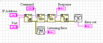
Try to connect to the power supply via the IP address
Hello
I am trying to connect to a power supply of Sorensen XEL60 - 1.5 P. I have its IP address and port number, but I'm stuck on an error 63, cited at the end I tried the advice in this forum and online without success, including:
Disabling firewall
* the ip address ping command
* Tools > options > VI Server
http://digital.NI.com/public.nsf/allkb/6ccced1045c479d286256a3a00655123
Open all the ports LV wants
Nothing improves the situation. What I will try?
Thank you very much
Error 63:
LabVIEW: Serial Port receive buffer overflow.
=========================
LabVIEW: The network connection was refused by the server. For TCP/IP, make sure that the server is running and listening on the port you want to use. Firewalls can also cause a server to refuse a connection. To VI Server, make sure that you have enabled the server from VI tools > Options > VI Server.No reason to be a donkey to people asking for advice. I tried UKRAINE by the boards, conscientiously the profit and loss account.
I can actually get the power supply to operate on the VISA. It needed fixed two bugs, in the case where others are interested:
* Setting VI_ATTR-TERMCHAR_EN to VI_TRUE
* Creation of the resource VISA under the 'manual entry of the raw socket"rather than one of the other two. This is necessary because I'm trying to communicate via a specified port.
So I'm fine now, I just can't pass strings directly via IP and port that I thought I should. It may be a device-specific problem, but I'm always interested in other thoughts.
Thank you
Warren Harding
-
BlackBerry Smartphones loading very slowly via USB power supply laptop
When I use the wall charger, my fine storm costs.
But if I connect it with the sync cable to my laptop - laptop is turned on with the BB Desktop software running (and I can confirm that I have a backup of the BB Desktop software then the drivers seem to work), the storm is charging is very very very slowly or not at all.
Is it supposed to load OK via USB to the laptop power? How can I go on troubleshooting this?
Your question is not a problem, but normal and the answer "why" is simple. Wall charger puts out simply more power that the USB port on your laptop needs to (or can). In general, any single USB port is 100-150mA (and can be lower if your running on batteries and the system is allowed to control the ports), while the wall charger is to switch off a little more (700mA)... constantly.
Not to mention that when connected to the laptop there is communication that passes between the device and the computer, especially if you use the Desktop Manager, which makes peripheral 'work' and try to reload at the same time. Sometimes the ' workload ' can be greater than the rate of charge, so why he does not pay at all.
IMHO, load your device with the supplied charger. Only use your computer to charge your device in case of emergency. If you insist on charging the system with your laptop... Plug in your laptop computer, close the Desktop Manager and Device Manager and it should load a bit faster.
-
Chroma DC power supply RS232 communication (read problem of over-voltage and current)
Dear all.
I chroma programmable DC power. Based on the programming of the Instrument manual I develop using RS232 communication. Based on the program I can set the voltage, current, over-current protection, protection against overvoltages and make IT / OFF out put supply perfectly.
But I have to read the measured values of the output power as current and voltage. Measured applications are the voltage and current of the output of the power supply. My problem is two of them read at the same time. Currently, the reading is only voaltge or current (if the first request is v? it is voltage read out but no reading for the current) and if the first request is CURR? the reading for the current, but not for VOLT? The status message is OK, even if it is to read values.
Thanks in advance
What I see in your program, it's that you do not use the stop for reading character. For your writing, you do the hard with all these concantanate string functions. You can set the stop character for all entries with a node unique propert - "ASRL end Out.
-
trying to communicate with a computer via an RS232 interface.
Hi, I would like to communicate with my computer via RS232 DB - 25 side of machine that is configured as a DCE and DB - 9 my side PC as DTE, the computer only uses pin 2 (serial data in), pin 3 (serial data out) and PIN 7 a pattern. I wired the pins straight through except the ground which is in the DB 9 pin 5, so I tried to connect pin 2 pin 2 and 3 pin to pin, pin 7 to pin 5, but I couldn't get through my machine, then I tried 3 machine spindle pin 2 of my pc , machine pin 2 pin 3 pin 5-7 pc, unfortunately cannot also. I set everything correctly, as I think, but somehow could not do.
(in the if said manual pc a DB9 so connecting db-9 to db-25 cable modem) - what a sense.
I'm asking for help on this issue. Thanks for any help.
Yes, of course do you. Who is stated in the manual. In MAX, you would use \r\n.
-
I want to drive a magnet with a power supply (you want to increase the tension of the first negative to positive then negative or vice versa) using LabView programming via rs232 port. I'm at the beginning of learning LabView. Could you please suggest some ideas for programming and communicating via this port?
Grimaudo
Open the file "C:\Program NIUninstaller Instruments\LabVIEW 8.6\examples\instr\smplserl.llb\Basic series writing and Read.vi".
Refer to m, annual instruments for commnads who recognizes the device.
Write the command in the field 'string to write' and setWrite and read about True. Run the VI. See what's happening.
-
Creating a power supply Variable myDaq
Hello world
Just got my myDaq NOR the other day and just start playing with it.
I was a little disappointed to know that power supplies were not Variable (i.e. fixed 5V and +/-15V), but that's what I have for not reading the fine print
.I thought a Variable power supply would be a good pleasure first of all of the project, but have no idea where to start. I was hoping that you guys could give me some advice/point me in the direction to look.
I intend to use myDaq for mainly breadboarding for laboratories after EE.
Since the 5V power allows for the most recent shooting, I think it would be the first supply to build.
Can someone point me in the direction to move forward?
Thank you!
-Ernie
Hello Ernie,.
Function of the desired output voltage and and currently, there are a few approaches you can try.
Buffered outputs analog is the easiest method. You could probably get to +/-12V if you choose a small enough margin requirements with op amp and add 20% gain. You would use the +/-15V rails to power op amp (don't forget to consider the tolerance of rail), and you should limit your output to 32 spec my the +/-15v rail. The buffer is essentially a linear regulator, so be careful of the power dissipation of the amplifier at high currents.
Output currents higher with lower voltages, consider using a switching regulator. There are a variety of topologies based on the input-output voltages. Look for Buck to withdraw to an input voltage higher than a lower output voltage; Boost to intensify; Buck-Boost to step upwards or downwards. There are others, but these are simpler to start. You can use the outputs analog of the myDAQ to inject a voltage error in the feedback from the regulator to allow programmatic output voltage control. Take a look at sellers sites power supply chip (TI, Analog Devices, Linear Tech, National Semiconductor, etc.) for application notes and recommendations from component.
Another approach is regulatory digital switch command. These provide a detailed and read back functionality via a digital interface to the chip. Google "digital power" for ideas.
If you need more power, you will need to provide an external power supply or battery, but control could still come from the AO myDAQ or digital interface.
It can be a difficult exercise, but I hope this help to get you started.
Charles Y.
-
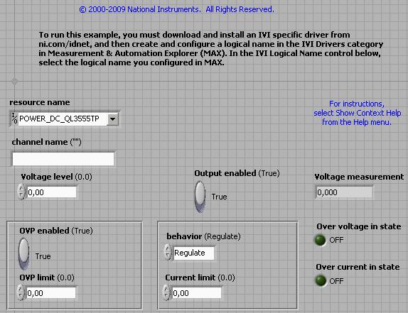
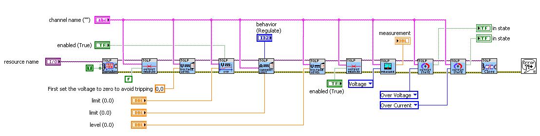
Problems with the DC Power supply QL 355TP: I can not set the tension level
Hello
I'm trying to control a power supply DC via GPIB. The power supply being used is the QL355TP of society Thurlby Thandar Instruments (TTi). There are no drivers of OR to control the instruments, then I need to download and install the driver from the website of TTi: the package I installed is as follows:
"QL - P power supplies, (including QL Series II) series pilot National instruments (Labview and CVI)"
and I also installed the following:
"QL - P power supplies (including QL Series II) series, IVI driver"
So, my problem is that when I try to use the sample application of the driver 'Volts.vi DC Ouput'; defines a specific level voltage, does not work properly. The application gives no error, but it is not set the specific level voltage. However, other functions work properly, as the measure or activate the output. I tried a lot of things, but I don't know why it does not work.
I enclose the block diagram of the application and the front panel:
I must say that I barely control instruments using Labview and is possible that this problem would be because I did not consider things basic and mandatory.
Any help is appreciated.
Thank you.
p.s. Try to replace the decimal comma to period. It is possible that the driver does not correctly handle the comma.
Maybe you are looking for
-
Windows XP on Satellite L300D-10U
Hi all I have a question, how can I install windows xp on my laptop Toshiba Satellite L300D-10U?Where can I get the drivers from?Do I need a windows xp cd with the drivers for the hard disk? Thank you
-
6.1.6 spinning wheel on Mac 10.7.5 Safari
Again, my computer knows the dreaded spinning wheel Safari! I have had this a year or two ago and so switched to Google Chrome and Firefox but apple told me that Safari has been so much more secure so I went back to Safari without problems for at lea
-
I managed to convert my iPhotos library to the News Photos 1.3 when I installed El Capitan 10.11.2 on my MacBook Pro. Since then, it has been impossible for me to create a new project, because 90% of the time when I try to change the font in a page,
-
Please I have android wintouch peripheral Q91,
Please I have android wintouch Q91 device, It is not open because forget the password if you can help, thanks.
-
Max EliteBook 840 G1 DisplayPort resolution
HP Elitebook 840 G1 Product # F6A08UC #ABA Intel(r) HD Graphics Family Windows 7 Professional 16 GB OF RAM 1600 x 900 screen integrated Could someone tell me no doubt taken max resolution supported on the DisplayPort that laptop? I make sure, that i