control thermocouples
Hey, I have a strange problem and I hope someone can help. I have been using a program for about 6 months now that basically keeps a cold temperature next to a heat sink and maintains a warm temperature on the other side. Then I 25 hung in the meantime thermocouples to measure temperatures I can do the analysis of the material in the environment. My problem is that all of a sudden the readings of the thermocouples were out of control and unpredictable. I add me automation program so it could run several tests at the same time and in the process developed by this problem. The weird part is that the problem is also past in the old version of the program now too, and that has worked perfectly for the last 6 months. I have 25 hung thermocouples and temperatures will all look all right, but then 3-5 of them will be quite wrong at random. What is interesting about this problem, it is that when I change the thermocouple which become the use of heaters to maintain the set temperature, the values that were wrong again on the right and some other thermocouples start giving invalid data. The installation program uses a NI 9213 and 3 NI 9211 inputs for thermocouples. It also uses one OR 9401 to control heaters through a box pulse width modulation power we have. Someone at - he never experience something like this or have any ideas? Thanks for any help
Hey Nathan,.
Thanks for the ideas. I ended up spending to playback of multiple samples as you suggested and this error has not popped up once again, so hopefully that fixed this issue. I think I solved the problem of both weird thermocouple readings! I think that I had a ground loop problem which I fixed it by the grounding all thermocouples to a metal table. For all those who on their getting odd unexplained readings, certainly experiment with ground everything correctly.
Tags: NI Software
Similar Questions
-
Control of data using multiple thermocouples via indicators and the waveform in real-time
I apologize in advance for this question is probably a bit simple but I'm all new to labview and the forum and could use some advice. I have a CompaqDAQ with two 9213 16 modules of track and I'm trying to read in 30 thermocouples in a waveform, but also display 30 indicators so I can mark each indicator with the thermocouple for real-time tracking. Each thermocouple corresponds to a specific location and it is essential that the interface has an accurate indication or a label for each of them. I wonder if there is an easy way to do this in addition to split the signal and have 30 thermometers on my diagram? Perhaps a table any? If I use a table to create 30 thermometers, the DAQ assistant automatically sorts the thermocouples according to ascending numerical order. For example, would be the indicators of first and second on my interface automatically assigned to channels a0 and a1 of the first module, or should I do it manually? Even for the waveform? Thank you very much!
PS - Do not know if this message had need of more details, but let me know if more information is needed, and I'll give you!
I see that you use the DAQ Assistant to create your task. Now I understand why you may have about labelling. It is easy of the seller NOR spiel booting... But in any case, you already have a task to the MAX instead of use the DAQ Assistant? The interface is similar and there may be a step or two, but your end application will be more effective and you will have more options with your data and properties. For example, I tried to update the names of physical channel in the DAQ Assistant installation program, that it let you do, but it propagates that change forward to waveform chart legend. Also, I don't know any property for this dynamic data type node, although I never use it either. I suggest the setting up of your task and channels, Max if you'd give it a go.
Since I thought I didn't really takes you all the way with you help, I wrote another one. It uses a cluster, even if it's a bit barbaric. I thought that there was a more eloquent way to do by changing labels, but I could not it works as I had expected.
-
XNET Signal list control deployed to target RT OR-cDAQ-9133
I develop a VI to read and record the signals from the engine CAN. One of the requirements is that it will be a stand-alone application which runs on the target device, a device of real-time OR-cDAQ-9133 with a module NI9861. It also has a module analog thermocouple which is read and recorded alongside the CAN signals.
in any case, I did the front panel so that the user can choose the CAN signals of a drop-down list of all signals in the XNET database and then run the VI to display and record the signals. On the development of PC, it works as expected, I can change the signals before you run the VI.
When I build and deploy the project I am no longer able to do. The drop-down boxes are grayed out and do not respond to clicks. How to allow the user to choose signals to read and log?
I've attached a picture to better explain the control of front panel, I have for the user to choose the signals. Nothing complicated just to select the node and right click to create the control. The image is what it looks like on the development of PC, I have not a screen capture of the target device.
I was able to find a work around. I used an array of enum on the front panel controls that are then wired in a case surrounded by a loop structure for. This generates the signals XNET list based on the table of the enum. Probably not a more elegant solution, but it works and allows the CAN signals to choose in the front panel on the target of RT.
-
more info on the DAQmx control task
Today I came across an older post where I had some questions and Jeff· just Þ· Bohrer showed a good example, it's here:
I doesn't pay attention to the DAQmx task manages the part, but now some new questions of time came to my mind, I hope someone can give me some explanations...
Usually, when I'm working with some hardware with DAQmx driver, I simply specify the channel, and I use the VI of virtual channel create for my work I want to use.
Recently I read about benefits use MAX to previously create some global (?) of the tasks (for example a cDAQ with many modules and i/o channels) and using these tasks in a LabVIEW project. In this case I can just skip the 'Create Virtual Channel.vi', begins with the measurement with a "Start Task" DAQmx and stopping a VI 'stop the task', correct? However in the link above, the VI "Task of control" (next), first used with a parameter "commit" and during the closing of the measure, with a setting of "Cancel" (and no task to stop vi was used).
I threw an eye using the Task.vi 'control', but the info it is not too detailed, where I can find a few more details, or maybe someone might highlight the use and benefits of this vi? Sounds a bit 'funny' aid, as for the parameter commit: "Programs the hardware as much as possible depending on the configuration of the task."

So what is the difference between the use of the "task of control" in a code and do not use it (so when we use only the start and the stop task live)? Do we not the same behavior with the latter?
Thanks in advance!
Martins wrote:
The overall task configured max subject: we conduct research, so I always just develop for our lab, we do not sell anything. However, I have some questions related to a task configured and saved to the MAX:
- So I have a task created at MAX, I guess that this task will be usable only if I use it in a project of LV on the same PC? What if I need to move my application to another PC (but of course with the same modules cDAQ, etc., but perhaps under different numbers...)
The task can also be used with a .exe. You can export MAX settings to a file (file, export...) .nce, and then import the settings to a new PC. If necessary you can tweek the numbers.
- I would like to create an EXE from my code and don't run this EXE to our systems (not install). Y at - he tips that I should keep in mind when I create an executable from a project that contains a task of MAX?
I can't think of something special. Personally, I prefer to load the name of the task from a configuration file, you can also use a control on the front panel to select the task.
I have a feeling, when we need complete flexibility, the course of MAX isn't really practical, Yes? I want to say, if we want to for example programmatically recognize all our application materials and create tasks to ensure that all physical changes on the side of the PC in the future will not affect our code?
I agree that you have as much flexibility, but for my applications most of the time MAX provides sufficient flexibility
But this scenario could be documented for future users in the lab, I imagine, so what they have to do, is to recreate the overall task? What happens when we take the application as an exe on another PC and manually re-create the (I hope that quite the same) necessary global task with the same name that awaits the EXE? It works this way?
Thanks for the very useful info!
Edit: "Yes you can set a MAX task that includes several modules and channels so that they all have the same type of action."
This is also a limitation compared to the creation of code depending on task, Yes? I mean, using the DAQmx 'Create Virtual Channel.vi', we can even combine for example analog inputs with for example in a cDAQ thermocouple hunts...
No it is not a limitation, for thermocouple is entered analog. If you can combine them in LabVIEW, you can combine them in MAX.
Edit2: I really miss other docs of type "real demonstration" of the NEITHER! I could imagine a sort of case study examples where different material handling OR would be explained... Of course we can hunt together pieces of mosaic, but a more compact image could help a lot for those who want to learn faster
Ben64
-
Hello everyone.
I need to design a system where it is supposed to control two solenoid valves (for gas of 5 l/min flow), a thermocouple and a moisture sensor. I have a few questions with respect to the foregoing:
1. what valves would be ideal to achieve flow rates of gas of 5 l/min.
2. is if possible to use NI - USB-6009 to control via PC or some other hardware DAQ system the above would be better
3. what additional devices are required in the above configuration
I'm looking for some preliminary information that could help me get started with the aforementioned project. Any help would be greatly appreciated.
Deepak
(1) do not know...
2) the 6009 will be have limits, no hardware timing for cardiac control loops, can not read TCs, if it's a school or a University project, take a look at the myRio. I'm not shure if it can read the TC directly, but you can easily connect an i2C / SPI TC IC conditioner.
(3) you will need some vor to power external power valves and a pilot valve (at least a transistor and a diode) -
BNC-2120 thermocouple CCM with M6289
I try to use my of Ic CJC of BNC-2120 thermocouple sensor to measure temperature, but I'm not in a position to acquire it with mass M6289 endpoint device.
Whenever I do the labview program using the DAQ assistant, using ai1 as (by default in the appliance) physical channel and ai0 under the Ref. temp for CCM, it gives error daq this task is not specified.
I don't know what the program if 6289 can control the temperature directly probe or not.
Please help me in this regard.
Concerning
Anurag
-
NEITHER USB-6008 connect to thermocuples and pressure sensors, control valve
I am endevoring to build a gasification plant biomass for bench scale test process control plans. NEITHER USB-6008/6009 will be adapted for use as a data acquisition. I'll take RTDS, thermocouples and pressure sensors. I don't want to use industrial automation controllers. It is also possible to use the channel of analog output for sending signals to a control valve position (using sufficient current/voltage between the two drivers).
(1) OK. I just wanted to be sure that you were aware of the potential dangers.
(2) an RTD is a resistance that has small changes in resistance per degree of temperature change. To measure that you have need of a current source and a sufficient resolution in order to detect small changes. At 25 degrees C a typical RTD is 109,73 ohms and resistance ohms 0.38 per degree changes. If you had 1 my crossing this RTD voltage through it would be 109,7 mV and the voltage change of 0.38 mV by degree.
The resolution of the 6008 on the most sensitive range is 0.49 mV > 1 degree. The accuracy of the 6008 is 1.5 mV typical.
For a Type K thermocouple, voltage at 25 degrees is 1.407 mV and change by degree is 39 µV. Millivolt solving half of the 6008 translates into about 12 degrees.
If you need a source of excitement for RTD and a kind of amplification for thermocouples and RTD before she would make any sense to try to use USB-6008.
(3) I have not used anything except LabVIEW with DAQ devices and drivers. I think DAQmx can be used with MATLAB and other languages.
(4) the 6008 is the low range made by NOR. You will need to go to a more expensive camera or add signals conditioning circuits. Talk to your representative OR assistance in the choice of a suitable device.
Lynn
-
With the help of several NI USB-TC01 Thermocouple measuring devices
I am currently set up with 1 NI USB-TC01 (http://sine.ni.com/nips/cds/view/p/lang/en/nid/208177), and everything works fine. My question is, can Labview control multiple TC01s simultaneously or I have to buy the NI USB-9211 has (http://sine.ni.com/nips/cds/view/p/lang/en/nid/201881#) to manage multiple thermocouple measures at the same time?
Thank you
Ben
Ben,
I didn't know we even had this device but I think that all of the information you want are in the link below.
http://digital.NI.com/public.nsf/allkb/7A9DAE5554C9D503862576FC005A3908
If you use the built in program, it is four devices, if you are using LabVIEW, you are limited to 127 devices. I don't know if several windows built-in software should be used if you use a LabVIEW.
-
PID control cool instead of heat
Hello world
I had a quick question about the PID vi in labview. I use it to try to cool an a box (measured with a thermocouple) and maintain at a certain temperature. The PID controls a fan that changes speeds in order to cool the area. My problem is that when I ran, I noticed that he seems to think that he has to turn less in order to cool the area (in other words not turn). Whenever I put my temperature is superior to the temperature, the fan would work, but below, it would not.
The fan will always be in a framework where the instrument will be greater than or equal to the desired temperature. Therefore the PID of the fan should work to lower the temperature, not more. Right now he seems to think that it is more than a heating unit. Does anyone know how to do this?
Ed
Try a negative gain factor. She will reverse the action of the PID.
-
Hi all
Please, I have an oven that I want to control the rate of heating of the radiator. I have the following equipment: cDAQ 9172, NI 9211, NI 9474 and a K type thermocouple. The specificatio of the radiator is as follows:
Maximum temperature: 1600
Voltage: 240 Volts
Watts: 4500
Ampere Max: 43.6
Thank you!
The simplest form of control in terms of hardware would be a relay that can handle the voltage and current to turn on and off the high voltage/current to the heater. Then your LabVIEW code would lead a digital output on the DAQ card that could turn this largest relay. Simpler control would strictly be power. You can also use a system of pulse width modulation that will pass the relay on and off to a rate. So, theoretically 50% right and 50% reduction in time would be about 50% of the heating power. You can use a configuration of PID control to determine what the cycle of your waveform must be a place any time.
-
question of thermocouple output
I'm having a problem with the release of the temperature, I want to take the temperature of output a compare it within a min that are given on the left side of the VI. But I can't take the output of the temperature one put on the middle of the comparison of the vi... But also I would make a case statement with automatic cut-off if fake? According to me, it's true, but I'm not sure on how to go about it. Any help would be great, I wanted to put the result of the comparison to the case so fake... statement as I said any comments would be great
You have already learned on stove and forced in another thread.
You can use a simple higher or lower to learn if a value is greater than a value Max.
But you're confused as to what the Min and Max controls are on the left side of your VI. They shouldn't be likely even controls. These entries to the data acquisition function set the analog input range of thermocouple chain. You set which, and then the value you read by definition will be equal to or less than the Max. You can read a value that is greater than a value when limit you the range of entries analog to this value.
Set the analog input range of Max and Min a few constants that have a meaning for the thermocouple and the temperature values, you expect to see. Your control Max would be inside the loop and be what you are comparing your DAQmx Read value. Wire the upper exit of said by comparison to the Terminal stop of your loop.
In addition, your while loop conditional terminal is located to the rear. If you have a mistake on your DAQmx Read, you don't want the loop to continue. You want to stop.
-
How to test if the thermocouple is attached.
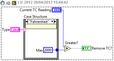
Hello, I use the cRIO-9023 and the module NI9213 to read the temperature of the thermocouple. I give to the user up to 16 thermometers already programmed in labview to display the temperature. The question I have, is I want to disable the thermomiters if no thermocouple is connected. I called NOR and they said there is no function integrated to test it, so I have to check by comparing the value. for example, if the units are set to fahrenheit, so if a thermocouple is not plugged it reads to the as 2500 degrees, so what I want to do is to check if the type is fahrenheit and if this is the case, then my temperature max value 2000 degrees. Then I can test IF temp? 2000, disable thermomiter.
How can I editor a programming like this statement:
If Type = Fahrenheit THEN maxTemp = 2000
ELSE IF Type = Celsius THEN maxTemp = 1500
Basically I want a boolian to trigger an action to establish an indicator.
Also, if I put an indicator of value of the dome, how can I read it by another controll?
I would like a way to do it without globial/local variables as my cRIO dislikes the.
Thank you!
Use an appropriate comparison function. Most important in this case.
-
Selective sampling of multiple thermocouples
I am using a chassis cRIO 4 to sample and record up to 64 thermocouples. Right now I can only sample the whole 64 channel set, but my desired product is a program that can taste and record any subset of thermocouples, selected by the user from the front panel. The best with what I came is using controls Boolean to enable the output of the unselected channels '0' and a series of LED next to the chart legend to indicate which channels record the true values and recording '0 '. I want to use Boolean controls to avoid that the registration to all deselected channels program. I have attached a few photos of my program. The first is part of my function of data acquisition, which takes the value of each thermocouple and places it in a table to draw on the graph and save. PDM file. The second is a part of the chain of function name, which combines the names in a table for the. TDMS file and sends each name to an indicator beside the chart legend. The third shows the chart, with all channels unchecked and without name. Does anyone have any ideas how I can do this more easily extensible program from the front panel?
I'd work with arrays and clusters instead of use explicitly each channel name, etc..
See my sample code attached. It is very simple, but should give you some ideas.
-
CYC can be used for several measures thermocouple?
Hello
I intend to use a PCI 6221 with the SCB-68 to 3 temperature measurements (2 on a surface of copper that will be controlled at 40 ° C) and 1 for air at 20 ° C using thermocouples T and cold welding of the SCB-68 Compensation. From what I understand, once that the switches were properly set, AI0/AI8 are used by the CCM. So I have to use AI1/AI9 in differential mode for my first Thermocouple.
(1) will be Thc n ° 2 and n ° 3 (respectively placed in AL10/AI2 and AI3/AI11) be Thc also compensated by CCM?
(2) does anyone otherwise a kind of accuracy can I expect with thermocouple T + CJC allowance? Ideally, I would like to join a +/-0.2 ° C accuracy.
Thank you very much
User
(1) will be Thc n ° 2 and n ° 3 (respectively placed in AL10/AI2 and AI3/AI11) be Thc also compensated by CCM?
Yes
(2) does anyone otherwise a kind of accuracy can I expect with thermocouple T + CJC allowance? Ideally, I would like to join a +/-0.2 ° C accuracy.
First, take a look in the spec 6221. in the CCM SCB - 68 spec and finally to the specification of the TC used. Rough estimate: +-2 ° C without individual calibration.
To meet the uncertainties of 0.2 ° C for type T TC (without the CJC and EMF meter) only you would need a calibration of liquid bath agitated the point of interest.
0.2 ° C is for RTDS like Pt100...
-
To begin with, I am very new to labview and unfortunately on that my first task is to build something rather complicated for a project that my company works. Fortunately it is especially followed rather than control critical processes.
Currently, I have a cDAQ with modules, DI, AO, and TC.
cDAQ-9133
NEITHER 9472
NEITHER 9421
NEITHER 9263
NEITHER 9205
NEITHER 9212
I'm currently running read-write for all 5 of these modules in parallel while loops and analog and digital inputs/outputs modules that all work as expected. Each loop requires 1 sample per channel through the wizard DAQmx etc for each module and I got can interact with all the asyncronosly inputs and outputs which at the moment is the goal. I can switch power switch for each module save memory, or if the need arrives later.
My problem is that the module TC (NI 9212) when tilt on which allows the acquisition of sample 1 loop seems to take much, much longer to collect samples. I have played with different acquisition parameters and can seem to get a continuous flow of data when you use streaming samples, or even when specifying N-samples but I come in questions where the "application cannot catch up with the hardware.
I tried to find an optimal number of samples/sampling, rate, etc I can get an update of temperature more than every 1 to 2 seconds, but if I set the number of samples that are high enough to apparently get a constant flow, what ends up happening waveform graphs seem to lag behind the actual data, and that's where I get errors. I only want 1 sample per channel per cycle anyway. Yet once, all the other modules in the cycle with less than 100ms delay between acquisitions but the module thermocouple ends up being 1-2 seconds. It's okay because in our application temperature should not rise/drop very quickly but its boring nonetheless.
I have the acquisition set up for the same (NI 9212) thermocouple module was like my modules of analog and digital inputs (NI 9205 and NI 9421) take 1 sample every time the task is called so I'm having a hard time understand why do the same for the TC module introduced such a delay. Max sampling rate is supposed to be 95 samples/s/ch, so I guess that the delay must come from call the task over and over again in a loop.
Synchronization and how you have configured the 9212?
In the case of high resolution, it can reach 1.8 samples/s. see page 7 of the plug technique here for rates for the supported modes:
http://www.NI.com/PDF/manuals/374389a.PDF
-AK2DM
Maybe you are looking for
-
Hello My HP Pavilion dv7 had no noise from speaker for the last 4 days. The headphone jack works fine, but there is no sound on the speakers of the laptop. I did a Hard Reset - this has not solved the problem. I also tried to use the IDT Audio instal
-
Pavilion 500-110ej: BIOS not shown on the screen
When I turn on my pc it starts directly at windows and does not show the BIOS/post where I could click f10 or something and niether, it shows the HP logo. When I hit the spam button f10, the screen remains black and white, my guess is that he entered
-
Windows Vista does not stop after that I'll start button in the lower left corner, and then select stop. It disconnects and displays a closing encircling the icon that will last for hours. It will turn off durng a reboot. It stops properly in Mode wi
-
Calendar default to change of blackBerry Smartphones
I get e-mail messages concerning the posst on Facebook on my Curve 9300 and the default device, Facebook for creating new appointments in the calendar. I don't want default Facebook and I don't need the Facebook calendar to all. How can I change th
-
I had CC Photoshop and Lightroom last January. Everything was ok until my PC has had some problems and the tech had to reset. I lost PS, so I downloaded again assuming he'll charge me again, but this month, he made a double load. I checked on my acco