Correct configuration for a measurement of voltage of 5 signals of pressure 4-20mA with a common GROUND (see photo)
Hello!
I intend to use the NRSE-installation for 5 meters of 4-20mA pressure that share a common GND. I drew a diagram of physical connection according to the wiring diagram that suggests the DAQ Assistant. However I do not know if it's okay or not...  500 ohm resistors are for the conversion of the 4-20mA 2 - 10V. I use a NI USB DAQ to 6353.
Does anyone could check the diagram for me?
Thank you.
Hello!
As far as I know, it should work.
Seeing your chart, I suppose you want to use (pin 1) AI0, AI8 (axis 2), (axis 4) AI1, AI9 (PIN 5), AI3 (PIN 10)... and AISENSE (13-PIN) to a common reference. If so, this should be OK.
Tags: NI Software
Similar Questions
-
Correct configuration for access Fiber Channel AAA
Hello all, I have searched for the correct configuration access the MDS 9124 fibre channel passes to the CSACS 1121 with 5.4.
I find pieces, but I'm probably set up groups incorrectly.
On the side of the switch, I have this:
FiberA (config) # executed sho | include the aaa
AAA server Ganymede group + sasTac +.
AAA server Ganymede group + yokTac +.
RADIUS AAA radius server group
AAA authentication login default group sasTac +.
Accounting sasTac AAA + default group
RADIUS-server key 7 "09754F021046461S020731".
RADIUS-server host 10.7.4.22 touch 7 'fewhg '.
RADIUS-server host 10.207.5.21 touch 7 'fewhg '.
RADIUS-server host 10.207.5.22 touch 7 'fewhg '.
RADIUS-server host 10.7.4.23 touch 7 '09754F021046461C020731 '.
RADIUS-server host 10.7.4.24 touch 7 '09754F021046461C020731 '.
AAA server Ganymede group + sasTac +.
Server 10.207.5.21
Server 10.207.5.22
AAA server Ganymede group + yokTac +.
Server 10.7.4.22
RADIUS AAA radius server group
On the side of the ACS, I have cisco-av-pair = shell: roles = 'admin network' for the command set.
Groups in the switch are the remains of the previous configuration; However, I can't find the setting anywhere in the old ACS version 3.3.
On the post of Jatin Katyal, I found links to explain the implementation of devices, but the links are dead.
EJ
I am pleased that you guessed it running. Thank you for posting to the forum and let us know that you fixed it and what you have done to address them. This information could be useful to some other drive in the forum who will work with these switches at some point. It's this kind of information sharing that makes the forum so useful and valuable.
HTH
Rick
-
How can I measure the voltage of a signal?
Well!
I'm trying to read the voltage of a signal using acquisition data PCI-6229 card.i am giving the signal as an input to the DAQ card and try to read the voltage level. The range of my signal is 4.8 ~ 5.5 VDC but the results are not accurate, such as measured with DMM. My code is as follows:
1.i m using DAQmx create channel to create an analog input channel
2. then a sample clock with finite samples, sampels by channel and set the rate of iteratively
3. then I start the task
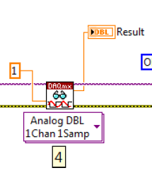
4. analog playback 1 DBL AK1 N sample d
Pressure readings I am differs widely that the actual.e.g a signal measured with DMM is 5v but when applied to the DAQ hardware and measured gives 6v.also I have to define minimum values and maximum in VI... If I put 4 to 5 maximum and minimum to measure a 5vDC signal it gives good result. , but if I change the maximum setting to 6v then it gives me results.also bad behavior is different for different signals for example when I measure a 6.5 VDC to signal that it shows me the voltage as 7.3V...
Photo of my code of VI is attached... Please answer... or give me another code that works fine at the voltage of a signal reading.
-
Measure the voltage and the temperature at the same time with a single card PCI 6014 DAQ?
Hello guys,.
I'm doing a charger measuring the voltage of the battery, the charge current and the temperature of the battery using a 6014 cardboard...
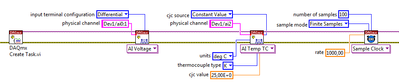
I want to use my PCI6014 DAQ card to measure 2-channel analog voltage input and 1 temperature Channel Analog input using thermocouple type k measurement of voltage or temperature isolation is OK, but I can't understand how to measure the voltage and the temperature at the same time... I want to use input differential...
Thank you in advance, all the tips
YSL
Create a task and add channels to the task, as follows:
Christian
-
measurement of voltage battery pinout 1.5 V AAA DC with acquisition of data USB-6009
Hello, I have a very basic question with pinout when measuring 1.5 V voltage on a USB DAQ 6009, using an AAA battery. Is it okay to connect (+) to AI0 and (-) to such AI4 suggested in MAX?
Nothing else required?
(attached pinout)
Thank you
Hi feanorou,
Yes, you have the Terminal configuration as award-winning, then using the 0 pine as AI (GOT 0 +) and using PIN 4 HAVE (I - 0) is a good setup for measuring the AAA battery.
-
Complete noob - would like to measure the voltage to manual start and stop
Hello
As the topic says I'm a complete noob when it comes to programming OR.
I'm looking for someone to point me in the right direction
Installation program:
Windows8 office
Visual Studio 2013
NI 6255 PCI data acquisition card
Block connection OR SCB-68
What I want to do:
I want to write a console application to measure the voltage on the signal ai16
-I want to be able to start and stop the application manually
-I want to be able to pressure measured in a CSV output.
Where I am:
I compiled and ran the example "NOR-DAQ\Examples\DAQmx ANSI C\Analog In\Measure voltage.
It is said that I have "collected" samples but I don't know what that means, as I do not see an output file...
What I don't understand:
Samples - I do not understand cela or know even where to start
How can output file - I get the file to save the collected data.
Thanks in advance
Chad
Hi Arron
Thanks for the link, unfortunately, it has not helped because the instructions were for Visual Basic and C++ not. It was my fault for not putting the language of prog that I need help in my original post.
However, I started to find help on this link: http://www.ni.com/tutorial/5409/en/
-With the help of NOR-DAQmx in text based programming environments
-
Here are two correct graphics for the Pavilion dv7-4270us cards:
Here are two correct graphics for the Pavilion dv7-4270us cards: ATI Mobility Radeon 6370 AND AMD880G with ATI Mobility Radeon HD 4250?
An overview chart problems and need to ensure.
Well, after all the day I found my answer in a review of this laptop on amazon. That is this HP forum. I never get help here.
-
Need help with the function or metric derivative to calculate percentages of threshold for a measure
Hi, first post to the community that I am a n00b Foglight needing help.
A thing (in fact the only thing) I like Microsoft SCOM is how this graph of the availability of a metric, and I want to do the same thing in Foglight. I understand that this could be a derived measure or a function, I need, but am a bit lost right now.
Let's say I have a metric and created thresholds as follows: normal included 0, 50 inclusive, warning critical 75 inclusive, fatal 100 inclusive + 9999 included. The metric is measured every so often and more often (99%) of the time it's normal. I want to visually represent that fact, together with the percentage of time that he spends in the strips of quick, critical and fatal alert threshold.
For the dashboard but mainly reports I am looking for the percentage of time that the metric through each of the bands of threshold and put them in some form of chart, preferably very similar to how SCOM it: -.

I would also like to increase this visually with a quantification for the oriented numercally, in order to insert values in the report for clarification would be great too, for example:-Normal:-99% 0.5% warning critical Fatal 0.1% 0.4%
I think of what I have already learned that we have to include a 'blue' band for threshold indefinite in order to operate on a regular basis for any measure.
I do not seem to come up with this concept in Foglight but I think it could be very useful to have something. Any help is most appreciated.
Health and alarms is a standard display which can be used on any object topology. You can access it from the data browser and should also be able to specify this dashboard as a preference in personalized dashboards.

Here it is in a custom dashboard:

-
My e-mail and password are correct when I try to configure my mail in Thunderbird, but I always get the error message: Thunderbird could not find your e-mail account settings.
I have also entered with Gmail and was assured that it is configured for IMAP
Thank you.
-
How to create a controller for the window "Configuration of spectral measures.
Hi all
Problem: We know that to change the 'window' for spectral measurements. There need to double-click it, the spectral measurement set-up window pop up and select regardless of the window (for example, no, Hanning, Hamming, Blackman Harris etc.) we like to not view. Instead of double click in the diagram, I would like to provide users a controller of the window in front panel as a list, so that they can select the type of window appropriate according to the needs.
I find how to solve it. Can someone share their knowledge have her number?
Right-click on spectral measures and "convert to Subvi. Right click on yellow VI that appears and click Open the front panel. Replace the constant 'Spectrum Window' with a control of enum (0 = None, 1 = Hanning, 2 = Hamming, etc.).
-
measurement of voltage longer distant
Hello Forum,
I have a very important question. I want to measure the voltage difference between two locations on a surface which are location 100 meters. So I'm going to use long cables. The sensors are reference electrodes. What connection mode will be the best for this measure? Single Ended (one of the references in the ground), which is the difference?
Any ideas will be greatly appreciated and kudo'ed
Hello
I'm not familiar with the reference electrodes, but I think I'd go with a differential configuration for your application because of the length of the cable (I'm guessing 2x50m or more?). Here is a tutorial about voltage measures: http://zone.ni.com/devzone/cda/tut/p/id/7113 I hope that you will find some ideas on it.
The problem is that any current through long threads will cause a voltage drop noticeable across the cable leading to the precision of the measurements. It is further complicated by different loops of Earth created between the ground potentials.
Best regards
Matej
-
Measure the voltage and the temperature simultaneously with PCI-6281
Measure the voltage and the temperature at the same time at the same time. However, when I put the voltage and temperature in a loop, the acquisition of voltage is significantly delayed. When I put the voltage and temperature in two different loop, none of them works. There is an example in aid of Labview as shown. This structure works fairly quickly? In addition, how a volgate get and temperature Analog DBL 1Chan 1Samp? I check the exported excel, the first column is 0, 1 the second column contains the value of the voltage, temperature value. I wonder how can I get these two values for each scan.
,
Assuming that the DAQ cards can handle it, you can set an analog trigger for the channel of the tension. Then you just X samples to get your 100us data value. Keep the last sample.
-
Measure the voltage of strain gauge
I have connected my 9237 to a 9945. I use a 350 ohm strain gauge. I have the voltage set to 2, 5V Max is there a way to measure physically to be sure that it is 2.5V? Also, in my vi I use a DAQmx create function of the channel. I want to add another channel for this but can't see how to do it.
Thank you
HS
Hi, Harry, it's Paul with engineering Applications to the OR.
My first question is why you are wanting to physically measure the voltage?
If you are wondering how that tension may vary, it is limited by the maximum capacity of 150mW of your device, as explained here: http://digital.ni.com/public.nsf/allkb/7CBC67482CC9FB318625758C0048FF73?OpenDocument
If you want to continue to measure externally, you have a few options. You can use another DAQ hardware to measure the voltage, or you can use another external device, like a digital multimeter.
If you want to see in the excitement that is actually supplied LabVIEW code, you can use the node property DAQmx 'Value of real excitement'.
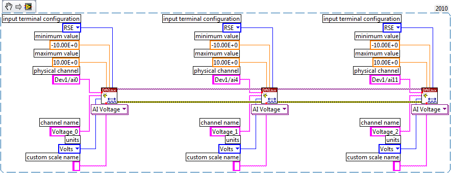
As far as playback of multiple channels, theres two ways you can go about it. If your channels are sequential and all have the same settings, then you can change your name of the physical channel to something like 'Dev1/ai0' to ' Dev1 / ai0:3: to specify the first 4 channels.» Alternatively, if you wanted to select non sequential channels, you can chain create channel set tasks, as long as they are of the same type of task (AI voltage, etc.) and the same device, as shown below.
Let us know if you have any other questions.
Kind regards
Paul
-
Sampling rate higher for the measurement of precision meter
I have a BNC 6259 M Series DAQ USB. I am currently using the DAQ Assistant to perform simple cash rising measured with the measuring mode single sample on request. I tested my VI with a known square wave with a function generator signal and it clearly lacks a few edges. I think that the solution lies in faster sampling. However, I was not able to understand how to use clocks to set up continuous sampling mode. I tried the forums and I found articles that were close, but not quite exactly the problem I am facing with as (http://forums.ni.com/t5/Digital-I-O/trying-to-use-NI-6251-s-DIO-port-as-input-and-output/m-p/448035#...) or (http://forums.ni.com/t5/Multifunction-DAQ/Using-Counter-of-PCI-6024E-with-Quadrature-Encoder/m-p/984...). Any guidance here would be great.
In fact, the calendar should not have anything to do with the edges being detected. Configuration of a sample clock for a county of just edge task allows you to enjoy deterministically in the account register and has no impact on the edges which can be counted. Also, the analog examples really have nothing to do with what you seem to be asking questions on.
... So it leaves the question unanswered as to why you might miss the edges. Perhaps the following information could shed some light on the question:
1. it is possible that you do not configure the counter exactly as you think you are. Can you post the VI you use? As a point of reference, count digital events shipping example does not use any clock sample timing and just questioned the value of the register count with a software loop, but the meter should not miss all this edge on the input source. There are examples that are timed by the material available as well, but this is not necessary, unless you need a constant specified dt between your counter samples. To use the examples of the timed sample, you will need to generate a clock of either another subsystem on the map or use an external clock.
2. assuming that the configuration of the counter is not the issue, there may be a problem with the method that you use to determine if you are away from the edges. How do you know that you are away from the edges? The function generator produces only a finite pulse amount? You start the meter before start out impulses?
3. If the two points above do not raise red flags, it seems likely that the meter is registered just not some of the impulses of your FGEN. Can I assume that the output of the FGEN is 0 - 5V TTL? What is its frequency and duty cycle? The maximum external source for the meter on the M-series products: DAQ (like the 6259) is specced at 20 MHz, but this depends on a clean signal with good connections. At frequencies above it, the bandwidth of the front-end of the PFI lines becomes limiting. If you have an available specification document for your FGEN I'd like to be able to see it.
I hope this gets you throw on the right track to solve the problem - impatience comes back with more information.
Best regards
-
Common ground for a precise measurement and analysis
Hi all
I wanted your opinion on input and analog output configurations. Connect us two resistors in series and provide an output signal analogue sine through it 10 V. Then, we measure the potential across the two resistors using differential input configurations, on the channels 0 and 1 AI. What I am curious about it is:
(1) do we connect the ground of the analog output and analog input mass together?
(2) if they are interconnected, so am I right in saying that the two potentials measured on the differentialchannel are referenced to a common ground?
(3) that help to improve SNR?
Will be grateful for your responses. (Two resistances here are an example of simulating loads through which am measure potential).
see you soon,
As mentioned, usually GND terminals are connected internally, so there is no real need for an additional connection between the GND AI and AO GND Terminal.
If you connect to them outwardly there is risk of creating a "ground loop", i.e. a closed circuit which cover a certain area that can capture the sounds of the environment. "Double earthing" should generally be avoided. However, perhaps in your configuration you will not see a noticeable difference with or without external connection - but it is evidence that the theory is wrong.


Maybe you are looking for
-
Could not open the Bluetooth settings HP DV8T-1000
I am running Windows 7 64 bit. I have the HP DV8T-1000 with built-in bluetooth. Software for bluetooth in installed (actually I uninstalled and reinstalled). Everything said "the device is working properly" However if I right click on the bluetooth
-
How to re - install windows without formatting of other partitions?
Hello world I had some problems with my windows on my laptop so I decided to re - install the windows. I have the DVD of my system recovery. So I used it to recover my system. Now the problem is, I had divided my hard drive to 5 partitions. 'C' was w
-
HP Mini 1000: HP Mini 1000 bios password reset
Is there a way to reset the bios password? I get the following message: Password check failed Fatal error... Systam stopped. CNU90256JY I searched and found similar positions, but posted passwords in those did not work for me. Thank you.
-
How to connect a laptop to my TV
How to connect How to connect a laptop to my tv
-
Hello, maybe I'm being a little worried, but I just finished chatting with a beautiful woman in technical support. After I told him my problem, she said she was sending a box I want to put my laptop in and ship back. Is - is this legitimate? (Because