measurement of voltage battery pinout 1.5 V AAA DC with acquisition of data USB-6009
Hello, I have a very basic question with pinout when measuring 1.5 V voltage on a USB DAQ 6009, using an AAA battery. Is it okay to connect (+) to AI0 and (-) to such AI4 suggested in MAX?
Nothing else required?
(attached pinout)
Thank you
Hi feanorou,
Yes, you have the Terminal configuration as award-winning, then using the 0 pine as AI (GOT 0 +) and using PIN 4 HAVE (I - 0) is a good setup for measuring the AAA battery.
Tags: NI Hardware
Similar Questions
-
Measure the voltage and the temperature at the same time with a single card PCI 6014 DAQ?
Hello guys,.
I'm doing a charger measuring the voltage of the battery, the charge current and the temperature of the battery using a 6014 cardboard...
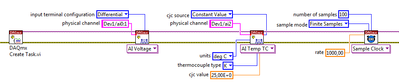
I want to use my PCI6014 DAQ card to measure 2-channel analog voltage input and 1 temperature Channel Analog input using thermocouple type k measurement of voltage or temperature isolation is OK, but I can't understand how to measure the voltage and the temperature at the same time... I want to use input differential...
Thank you in advance, all the tips
YSL
Create a task and add channels to the task, as follows:
Christian
-
Is it possible to a floating voltage with the output box usb-6009?
Hello
I was wondering if anyone knows how to a difference in voltage output 0 to 1 AO on the box USB-6009 DAQmx AO without reference to the ground. Any help would be greatly appreciated.
Thank you
Bryan
Hello
Page 19 of the manual USB-6009:
http://www.NI.com/PDF/manuals/371303l.PDF
Shows the internal circuits of the DAC are referenced to ground so there is no way to internally isolate it / provide any reference.
Maybe there is another way to make the desired effect? I don't know the details of your request to suggest everything.
Please do not hesitate to ask questions
-
Hello!
I intend to use the NRSE-installation for 5 meters of 4-20mA pressure that share a common GND. I drew a diagram of physical connection according to the wiring diagram that suggests the DAQ Assistant. However I do not know if it's okay or not...
 500 ohm resistors are for the conversion of the 4-20mA 2 - 10V. I use a NI USB DAQ to 6353.
Does anyone could check the diagram for me?
Thank you.
Hello!
As far as I know, it should work.
Seeing your chart, I suppose you want to use (pin 1) AI0, AI8 (axis 2), (axis 4) AI1, AI9 (PIN 5), AI3 (PIN 10)... and AISENSE (13-PIN) to a common reference. If so, this should be OK.

-
Measure the voltage and the temperature simultaneously with PCI-6281
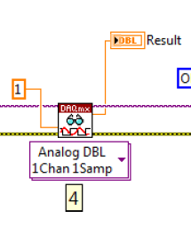
Measure the voltage and the temperature at the same time at the same time. However, when I put the voltage and temperature in a loop, the acquisition of voltage is significantly delayed. When I put the voltage and temperature in two different loop, none of them works. There is an example in aid of Labview as shown. This structure works fairly quickly? In addition, how a volgate get and temperature Analog DBL 1Chan 1Samp? I check the exported excel, the first column is 0, 1 the second column contains the value of the voltage, temperature value. I wonder how can I get these two values for each scan.
,
Assuming that the DAQ cards can handle it, you can set an analog trigger for the channel of the tension. Then you just X samples to get your 100us data value. Keep the last sample.
-
Measure the voltage of strain gauge
I have connected my 9237 to a 9945. I use a 350 ohm strain gauge. I have the voltage set to 2, 5V Max is there a way to measure physically to be sure that it is 2.5V? Also, in my vi I use a DAQmx create function of the channel. I want to add another channel for this but can't see how to do it.
Thank you
HS
Hi, Harry, it's Paul with engineering Applications to the OR.
My first question is why you are wanting to physically measure the voltage?
If you are wondering how that tension may vary, it is limited by the maximum capacity of 150mW of your device, as explained here: http://digital.ni.com/public.nsf/allkb/7CBC67482CC9FB318625758C0048FF73?OpenDocument
If you want to continue to measure externally, you have a few options. You can use another DAQ hardware to measure the voltage, or you can use another external device, like a digital multimeter.
If you want to see in the excitement that is actually supplied LabVIEW code, you can use the node property DAQmx 'Value of real excitement'.
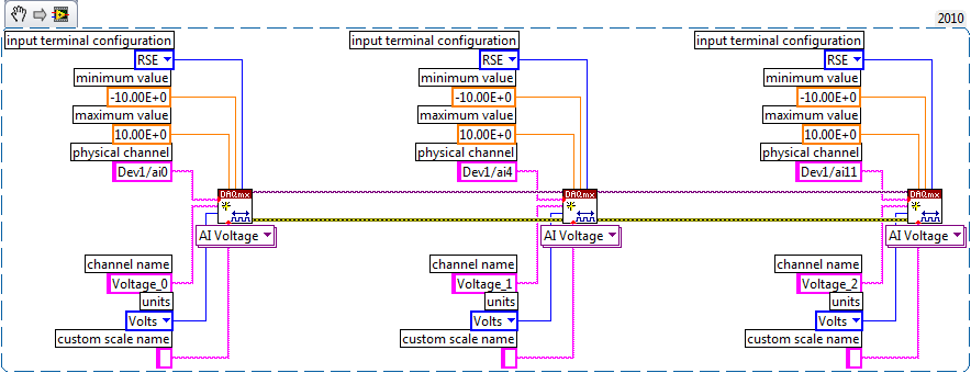
As far as playback of multiple channels, theres two ways you can go about it. If your channels are sequential and all have the same settings, then you can change your name of the physical channel to something like 'Dev1/ai0' to ' Dev1 / ai0:3: to specify the first 4 channels.» Alternatively, if you wanted to select non sequential channels, you can chain create channel set tasks, as long as they are of the same type of task (AI voltage, etc.) and the same device, as shown below.
Let us know if you have any other questions.
Kind regards
Paul
-
Complete noob - would like to measure the voltage to manual start and stop
Hello
As the topic says I'm a complete noob when it comes to programming OR.
I'm looking for someone to point me in the right direction
Installation program:
Windows8 office
Visual Studio 2013
NI 6255 PCI data acquisition card
Block connection OR SCB-68
What I want to do:
I want to write a console application to measure the voltage on the signal ai16
-I want to be able to start and stop the application manually
-I want to be able to pressure measured in a CSV output.
Where I am:
I compiled and ran the example "NOR-DAQ\Examples\DAQmx ANSI C\Analog In\Measure voltage.
It is said that I have "collected" samples but I don't know what that means, as I do not see an output file...
What I don't understand:
Samples - I do not understand cela or know even where to start
How can output file - I get the file to save the collected data.
Thanks in advance
Chad
Hi Arron
Thanks for the link, unfortunately, it has not helped because the instructions were for Visual Basic and C++ not. It was my fault for not putting the language of prog that I need help in my original post.
However, I started to find help on this link: http://www.ni.com/tutorial/5409/en/
-With the help of NOR-DAQmx in text based programming environments
-
measurement of voltage longer distant
Hello Forum,
I have a very important question. I want to measure the voltage difference between two locations on a surface which are location 100 meters. So I'm going to use long cables. The sensors are reference electrodes. What connection mode will be the best for this measure? Single Ended (one of the references in the ground), which is the difference?
Any ideas will be greatly appreciated and kudo'ed
Hello
I'm not familiar with the reference electrodes, but I think I'd go with a differential configuration for your application because of the length of the cable (I'm guessing 2x50m or more?). Here is a tutorial about voltage measures: http://zone.ni.com/devzone/cda/tut/p/id/7113 I hope that you will find some ideas on it.
The problem is that any current through long threads will cause a voltage drop noticeable across the cable leading to the precision of the measurements. It is further complicated by different loops of Earth created between the ground potentials.
Best regards
Matej
-
How to measure high voltage (60-70 v) and current (75-80 a) using a DAQ PCI or USB DAQ
Hello
I work with a system that works on about 5kW. The output of the system voltage can go maximum up to 60-70 v and thus the corresponding current around 75-80 a. I have 10 these systems that I want to read one by one continuously for long periods.
I am designing the automated system best suited for this and looking for the best material that would be appropriate for this purpose. Looking for options, I found that an SCC - A10 attenuator may be used to get the tension down by a factor of 10. But I'm confused, if the high current will pose a problem and also how to measure this high current.
I need to measure the voltage and current at the same time. Please suggest what would be the most appropriate fitting for the same (preferably PCI or USB)
The hope of a quick response. Thanks and greetings
Reena Sharma
Facilitated learning
Reena says:
Hi all
There is good news that the idea of using a compact data acquisition has been accepted by the authorities of the society. I'll be very grateful, if you could suggest me with some hardware modules suitable for my application and how I can use them best.
Thank you very much
Reena
I was able to make a few suggestions, but do not have the time to understand your needs and the forums are not the best solution.
Your Local OR representitive actully gets paid to do this kind of thing. a google search suggests THAT LME is in Pasadena. Zack Collins would be the contact rep
-
Measurement of voltage detection failure
Hello everyone
I am a new user of Labview and I try to measure a voltage but is facing difficulties.
I use:
Worm - Labview 8.0 on Windows XP
-Based electric circuit with a voltage generator and resistor for voltage
-A connection block 68 CBS
-A NI PXI 1042 chassis
But Labview seems unable to detect my acquisition circuit, I tried to use the DAQ assistant > analog input > tension in my new VI, but it has not detected any device.
I miss any point?
Any help would be welcome, if my explanations are not clear enough, you can ask me some questions.
Thank you for reading my post.
DAQ Assistant materials should not be your FPGA. Looking at different sets of drivers.
I expect to see the device in your PXI system, if Max.
To work with this device, you do not add the DAQmx code in your code and go from there. You will never get a reading. Instead, you add a target to your project. You have a controller in a PXI chassis or are you plugging it directly into your PC? If you have a controller, it is based on WIndows or RT? If it is Windows, you'll want to work from the PXI himself. If it's a RT., you should be able to see all of a remote connection. If it is not a controller, try to turn off your PC and PXI. The PXI power first and then the PC. You read only what is PXI chassis when you start your computer. If you have added anything to it, you will not see it.
I don't remember off the top of my head. But, I believe you'll right click on 'My Computer' in your project to see the map of the R series. Choose "New objectives" and search for your listing. If it is not there, right click on the project name instead.
For this device, ignore the DAQmx palette entirely. It is useless to you.
-
differential measurement high voltage
Not sure if this is the best place, but here goes.
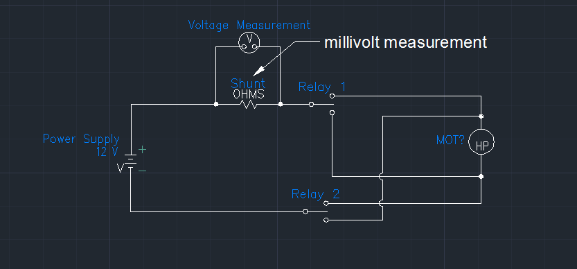
We are trying to measure a voltage differential across a shunt in offset voltage, which is then further +/-10V over data acquisition cards measure. Here's a representative diagram of our circuit:
We must also measure 24 of these shunts while we move the motor one way or the other. That in one case the offset voltage is near current of 12 volts (rank 9-16Vcc) that eliminates all the cards of the cDAQ and it looks like the PXI series too. We currently use one SCXI-1104 researcher but a USB port on a laptop for this measure. The SCXI-1104 has a voltage range of + / 60V and I was unable to find anything close to that in the product offerings of NOR. The reason why this is going to be a problem for us is that large corporation, we are forced to move to windows 7-64 bit and SCXI hardware are not supported for this operating system.
I am open to any suggestions that others may have to help us fix this problem.
Thank you
Bill Lane
We ended up finding some amplifiers that have been specifically designed for the high pressure shunts. Do a search on digikey for amplifier of high-side current shunt and you should be able to find something. These will turn the measure into a single measure is over voltage.
-
Measurement of voltage of bus DC-OR-9505
Hello
I would use the NI 9505 H-bridge module in a system of identification in car
where I have to measure the DC bus voltage as well.
NOR-9505 is capable of that?
Thank you.
Pros
Hi Pros,
The NI 9505 module is DC Servo Drive module. However, it does not provide general (voltage) inputs analog, as you would need.
However, I believe that you have chosen a modular platform like cRIO, which means that you can add another feature by adding a module over. Check voltage of series C acquisition products to choose the system best suited for you.
You can use NI 9215 to measure the voltage, for example more module NI 9505.
Best regards
S9ali
-
Measurement of voltage with NEITHER - 9203
Hello
Is it possible to use the NI9203 card for voltage? I need to replace one of the pressure sensors that has output of sensor that has a single output voltage current and there is not any card with entrance to the machine. In the data sheet there is a block diagram of the input circuit of the card where R 138 Ohm is connected to COM. So, if I connect R aprrox. 360 ohms in series to the input card that I will get a voltage divider that will transform the voltage of 0 - 10V, 0-20mA current. It will work properly?
Thank you very much for the help!
Jan,
In theory, adding the external series resistance should work. I hope that it is a fairly short cable length and not a real noisy. You will need to check that the new sensor is able to drive a load of 20mA. You will need to take the resistance of the wiring etc. account when setting this up.
-
Measuring current using USB-6009 with a rheostat shunt resistance
Hi all, I am an electronic engineering student doing my final year project. I am able to measure the current and voltage of a 9V battery, but not knowing the method that I use if it is correct.
For the voltage, I have no problem getting it. But for the current, I connected a resistance of 1 k in parallel with the battery. When I run the program, I have a 9mA for battery. I understand when you use the DAQ assistant, for the installation of measuring current for USB-6009, that I need to specify as "external" shunt resistance and shunt resistance value (which is 1 k for the above experience).
So, my question is when I use a rheostat as shunt resistance, what value should we indicate as a rheostat is a variable resistor, so it doesn't have a fixed value.
Or the dimmer cannot be shunt resistance?
Really need help and thank you for the reply.
-
measurement of current with usb-6009
Hi, my name is hung and I am a student in electrical engineering... I'm doing a thesis that the project using Labview and acquisition of data NOR UBS-6009 to simulate the function generator, Oscilloscope, Digital Microsoft (DMM)... and now I'm simulating DMM. I managed to measure the voltage and resistance which i use voltage divider method, but I encountered a problem with the current measurement. The problem is the USB-6009 to measure use the current, it measures an incorrect value. I tried to use the current CQI 0-20mA Sample.vi example but it always measures an incorrect value. If NI USB-6009 supports for the measuring current? Is there a way to measure the currents using USB-6009? Please, help me. This thesis project is so important for me. Thank you.
Hung,
Since you are a student in electrical engineering, I'll show you how to know the answers to your questions.
1. review the specifications for the USB-6009 case. In particular look at the specifications of analog input.
2. How would you measure current if you had only a voltmeter? Use the same method with the USB-6009 case. (Tip: apply the Ohm's law).
General comment: when using any measuring instrument, always consider maximum permitted values at the entrances so that the instrument is not damaged
and the measure is accurate.
Let us know how you do.
Lynn

Maybe you are looking for
-
Writing PNG file failed when build exe, but operate normally on the development platform
See photo below, it is used to call WinAPI for screenshot and then save it in PNG file. This Vi operate normally on the flatform of development, but it failed when building the application .exe file. The pop-up dialog error 'chain of illegal path, OS
-
The following update contains O Ko (KB967715) and tried to update for the past year. How can I stop this update?
-
I have 20 windows updates failed on my new computer with code 80072EFD and tried everything I know. Its still new with few programs on it so I could do another full system restore if I have to. I also have a free windows 7 for this computer that is a
-
HOW TO ADD AN ICON ON MY WINDOWS 7?
i.m trying to ad a new icon in my window 7. Please guide me. Thank you. Original title: how DO I AD YEAR ECON to MY WINDO W 7
-
What format to use when you try to download videos on instagram or even try to send an e-mail
What format to use when you try to download videos on instagram or even try to email them