count the pulses ttl only on 2 V
Hi I have a problem while I was trying to count a pulse ttl using the DAQ Assistant. The problem can be simple, but I just can't solve that since I'm new to LabView.
There is a TTL pulse produced of our ODA that is about 30 ns width, 5V. I want to use LabView to perform the count of photons. But because of the noise, I want to put a number limit of 2V, so the software one count higher than 2V TTL pulse. But I can't do that. There is no option to set the limit.
And our material is BNC-2110 and PCIe-6323.
Can someone help me with this? Thank you.
For a counter entry, the minimum voltage for logic there is 2.2 volts - a ttl level. And no, you can not adjust higher.
Tags: NI Software
Similar Questions
-
How to count the pulses using RIO (FPGA)
Hello
I want to use RIO (FPGA) for counting the pulses produced by a sensor,
but I don't know how to program. can someone help me.
Thanks in advance
CAIX wrote:
Hello
I want to use RIO (FPGA) for counting the pulses produced by a sensor,
but I don't know how to program. can someone help me.
Thanks in advance
Search for example for 'Meter of RIO' finder. There are dozens of examples that should help you.
-
Salvation;
Here is the solution for your problem.
The cause is that "Gen dig Pulse Train-Finite" uses Ctr0 both Ctr1.
Please refer to:
"When you do a finite pulse train generation, a counter generates pulse train, and the other counter generates an impulse that acts as a barrier to the first counter. If you change the pulse train to generate continuously or
only generate a pulse, you can run two tasks of meter at the same time without error. »
http://digital.NI.com/public.nsf/allkb/04BEDD9E9E91ED3486256D180048116D
I used Ctr0 and Ctr2, jumping Ctr1 as it is reserved by "" Gen dig Pulse Train-Finite ". I works very well.
Kizito.
-
How to count the pulses with digital input on 6351
Hi all experts in Labview,.
I just got my USB x series 6351 and it works fine, but I certainly lack of labview skills to use it to its full potential.
I would like to read digital pulses with several digital inputs and count the number of pulses each T interval in time. All impulses that I entered on any edge of the clock are not synchronized and can occur at random times during the tests. Basically I have an oscillator of square waves can I modulate the frequency. I don't want to use the meter as inputs as I'm limited to only 2 entries (if I use the option 2 input meter for metering of pulses or frequency). The input frequency can range from 0-1 kHz and goes 0 - 3V. So not too fast, and I shouldn't make too many mistakes trying to get the count of pulses and then back out the frequency in accordance with article ni.com on counters.
I would like to read the 8 digital input channels and get the number of impulses for each channel. I searched high and low for help online but can't find examples that have been useful. Anyone have any ideas on how to go or direct me to a resource? Thank you very much in advance!
Are you worried about getting the number as a physical operation timed? It would be nice to acquire a digital waveform and then postprocess on it to detect how many events took place? I've attached an example that shows how you can accomplish this. It reads a digital waveform and then uses a detection of crete VI to determine how many pulses occurred. Should be a few adjustments to your particular signal. The VI I use seems to count events twice (probably count each edge), so counting it gives should be reduced by half in order to work.
-
How can I count the pulses in a channel?
Hello
I have a channel consisting of 0 and 1 (data comes from a proximity sensor) and I was wondering if there is an easy way to count the events (i.e. pulse) to (Advanced) Tiara? At its simplest, I just need a method to count the number of rising edges in the channel.
A script would be the way to do this? If so, is there any example autour code to demonstrate how to analyse the lines in a channel?
Thank you
PorridgeMan.
Hello!
@Martin: IMHO your aproach can operate, but need not because of input data and the right compares value (10 in your case).
If the input data are not a pure 0-1 step you can get more the a value greater than 10 for a rising edge.
The comparison value depends on the distance of time and the channel values, and it's not easy to calculate in advance.
The other drawback I see is that you need a channel of X, which is not really necessary to solve the problem.I think my code will be more robust (IMHO as I mentioned).
@PorridgeMan: Yes, it's a shame it takes certain steps of DIAdem to solve this common problem.
First: By script is possible, but generally to slow down. My approach is to insert a 0 value at the beginning
a copy of the input channel table and compare it to the input string. If a value is less than 0,5 (half of you maximum values)
and the other is higher I put a 1 0 otherwise in a result string. Even in more complicated cases, the comparison value could
be calculated or alienated by a moving average.
Here is the code:
Option Explicit

' Copy data
Call ChnCalculate("Ch(""[1]/Dif"")=Ch(""[1]/Pulses"")")
' Insert one 0 at the beginning
Call DataBlInsertVal("[1]/Dif",1,1,0,0)
' Compare and convert result to 1 or 0
Call ChnCalculate("Ch(""[1]/Result"") = IIf((Ch(""[1]/Pulses"") < 0.5) And (Ch(""[1]/Dif"") > 0.5), 1, 0)")
' Sum is result
Call MsgBox(Cch("[1]/Result",4))
Hope this helps
Matthias
-
Hello everyone,
I need to count the pulses of a digital signal. I looked at the examples associated with it, but all seem to use a signal acquired by a digital counter entry. I already have the signal in my computer, so using a device entry makes no sense. And the library of functions, I looked but found nothing. What features LabView should I use?
Thanks in advance for your time and help,
Pablo Concha
You can go there. 8.2
-
FPGA to generate the counter and pulse train
Hello
I have some experience with Quartus, but new on the FPGA OR.
I have a PCI-7811R. I'm trying to use it to illuminate sequentially 144 LEDs repeatedly. The duration of each pulse is 480us.
Basically, I need to generate a pulse and generator of a counter to record the number of pulses and, according to this number, select which light is lit.
I designed a pulse generator train based on an example of using FPGAS and added a counter in it. You can see in the attached vi.
My question is,
When I put the I/O node inside loops call single cycle, it can generate the correct pulse. However, when I tried to use the local variable to transfer data from the SCTL and then plug it on another node of I/O, I can't detect the pulse signal when I measured this I/O.
Is there something wrong with my code when I try to transfer the data of the SCTL? Can I also use local variable to transfer the value of counter, because I will need it in the next part.
Thank you!
If you are referring to the wired local variable to DIO2 in your attached VI, the problem is very simple: it is outside a loop, then it executes only once. Put this local variable and the node of IO in a loop and I think you'll get something close to the impulse you expect (although if it is not in a loop of single cycle you will have exactly the same calendar).
-
Count the edges of the 2 signals TTL (Heidenhain linear scale)
Hi all
This is my first post here. :-)
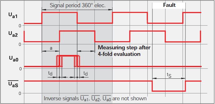
Currently, I'm doing a VI to be used with a linear scale. The linear scale gives 2 TTL signals that have an offset of 90 °. The change in distance of the linear scale is given by counting the fronts and edges of the two signals. See the following image: Ua1 is signal 1 and signal 2 Ua2. You can ignore the other signals.
Now, I want to count the 4 edges in order to translate the 2 signals in the distance. This means that I need advanced two counters for Rising-rising, Rising-Falling Falling Falling, falling on the rise for 2 signals. I tried to do 4 points two counters in LabVIEW but that of course does not work, because an acquisition of data can access the card TTL or I did it wrong.
Once I have to handle this, I also want to understand the meaning.
My card TTL: NI 9402
My electronic Heidenhain interface: 100 IBV (http://www.heidenhain.com/fileadmin/pdb/media/img/598_160-23.pdf - also at the origin of the image)
Hardware configuration: linear scale-> IBV (Elektronic Interface)-> NI 9402-> LabVIEW
Signals: Analog 3-> 3 TTL-> OR 9402
I hope I do not double post. Any help would be greatly appreciated.
I used Heidenhain linear scales in many applications.
As stated in the previous post, the output of your balance is as a quadrature encoder. Therefore, you must use an entry of the DAQ card counter to measure the position of the scale.
The desired X 4 mode is done by the meter itself (not possible with some old maps of OR).
As starting point, see measure angular Position.vi that comes with examples of LabVIEW. On your linear scale, change the type of the polymorphic DAQmx create channel VI CI linear encoder and etiquette of pulses per revolution at a Distance by pulse.
Feel free to post back if you need further assistance.
-
Count the number of 1 is present in digital waveforms obtained by converting the pulse signals.
Hello
I use Analogtodigital.Vi to convert the pulse of the sequences in digital.signals.I am able to get the representation of digital waveforms of impulses.
But how to count the number of 1 is present in the converted digital waveform. I want to count the number of 1 is present in the digital waveform converted.
Thanks in advance.
Have you tried the block scheme of similar to the Digital.vi of opening?
It creates an array 2D uncompressed 1 and 0, which is the binary 16 bits A/D conversion of each element in the array Y of the input waveform. You can use the DWDT digital Array.vi Boolean to convert a 2D Boolean table. Then convert Boolean values to 1.0 and summarize the array of integers. The sum must be the number of 1 bits in the digital waveforms.
Lynn
Note: The VI attached is saved in version 8.6. When I have it saved for the previous Version a warning was generated about the possible differences in the versions. Let me know if it doesn't work, and you are using which version of LV.
-
Hi all
I'm going through the phase of my small vi debugging and found an inconsistency that makes no sense. My goal is to generate a single TTL pulse as soon as I discovered a passage by zero of a sine wave. So, I generate a simple sine wave and send a logic true to the block which supposedly should initiate a TTL pulse generation. I first tested at 1 Hz sinusoidal and pulse TTL of ecu 1 Hz. I then put my sine funnction at 5 Hz, but I always only TTL signal of 1 Hz, instead of 5 Hz (1 pulse each time by resetting a sinusoid at 5 Hz).
Can anyone suggest where the problem is maybe?
Thank you in advance!
I think that your problem is easily explained by a single sentence in the help for the VI of passage to zero: "If wire you a waveform value or a dynamic data type value at the point of data entry, this VI evaluates only the first value of the input data."
-
How can I count the custom order?
I'm counting the number of names that appear in all the columns in the table
Each cell contains the name of a single individual, like the first column: 1-01, the second columns: 1-02, etc.
Can someone help me with the formula to measure? What would be the correct formula for this?
Thank you very much.
Hi the learner,
"I'm trying to count the number of names that appear in all the columns in the table
Each cell contains the name of a single individual, like the first column: 1-01, the second columns: 1-02, etc.. »
Your goal is not clear.
What do you mean by ' count number per ordercustom?
You want a single indictment which only has the names that appear in each column?
Do you want counts of the number of names appearing in each column (ie. a separate head for each column)?
You want a counter of the number of all the names on the table?
Or is that what you want different from all this?
"Each cell contains the name of a single individual."
Not mean there is no empty cell?
This means that there are no cells that contain data that is not the name of an individual?
I do not understand the connection between "1-01", "1-02 ' and the names in the cells.
Please specify.
Kind regards
Barry
-
How to count the number of conditionally highlight cells in a column or row
I'm working on a table to identify problems with my credit rating. So, I have a column that indicates the due date on the invoice and G that contains the date to which I made the payment.
I'm trying to follow how many times I'm late with payments. I want to improve.
So if the G column is later than column D, both with the Date formatting. So, now I've highlighted cells and I want to summarize for the year, how many times I was late payments.
I thought a column G to count the number of days before or after that back I was with payments. But if the sum, it only gives me no useful information. I guess I could count the number of cells with values less than 0.
I prefer to be able to put in the summary column for G something that said 0-12 years ago has highlighted cells in the column.
Thank you
You can not count based on sharing or formatting. You can, however, be based on the same conditions.
There are functions:
COUNTIF() counties based on a condition is true
and
COUNTIFS() based on several conditions being true
= NB. If
Here is a way. IT will take an additional column that calculates the "delay" in the days of a payment

the first two lines are the lines of header
H3 = IF (COUNTA (D3, G3) > 1, MAX ((G3−D3) DUR2DAYS, 0), "")
It's shorthand dethrone select cell H3, and type (or copy and paste it here) the formula:
= IF (COUNTA (D3, G3) > 1, MAX ((G3−D3) DUR2DAYS, 0), "")
Now select cell H3, copy
Select the H3 cells at the end of column H, dough
H1 = "payments late =" & COUNTIF(H,">0")
-
-Measurement of the pulse width specifies the timeout?
I'm trying to set up a simple project of Signal Express that measure the pulse of two separate signal lines width.
My PCI6224 has two entrances of meter and then run each pulse in the entrance of a meter line, respectively.
The I set up the express project signal attached, which consists of two simultaneously runnings tasks DAQmxAcquire. Each of them is set to measure the pulse for one of the pulse width. I then connect the results for further analysis.
This configuration works very well from time to time. The problem arises when the impulses do not arrive quickly enough and the acquisition of the timeout action. Looks like that has a simple solution - just increase the time-out - but I can't find a single setting around the affects, the time-out! The time-out period is always 10 seconds, regardless of what I do.
Can anyone help?
Thank you.
Hello rothloup,
Unfortunately, there is no option to change the time-out Signal Express for a task entry counter. This has been brought to the attention of our developers.
Reading a DAQmx LabVIEW VI has a time-out node you can specify the time-out period, even in the tasks of meter. I suggest you try to implement your system in LabVIEW (if you can).
Here is a tutorial on how to make PWM in LabVIEW.
http://www.NI.com/Tutorial/2991/en/
See you soon,.
-
Pulse ultrasonic 40 kHz and the time before receiving the pulse.
Hello
I developed the following circuits:
TX: a Circuit that generates a 40 kHz of frequency using a LM555, the LM555 is connected to a gate AND who, when you use the test on MyDAQ Panel (6216) I put cntr0 and set it to the detection of edge I can count the number of detections of edge when I activate the port up and when I turn it on it low stop recording of the counties.
Rx: Reception Circuit contains an op amp that is introduced in a LM567CN tone decoder which is set at 40 Khz. when the receiver PLL circuit locks on the 40 kHz signal switches LM567 pin 8 output ground.
Question: I am NEITHER very new and ask yourself where the starting point would be to create a VI that will trigger the Tx circuit, and then measures the time required for the circuit of Rx to receive the signal, this intitial will carried out through the air and then I want to move it through a meduim such as water. Someone at - he tried or seen anything that would be useful to create a vi that correspond to this.
Any help would be greatly appericated.
Phil
Using a myDAQ or a 6216? You mentioned the two... I'll assume 6216:
You'll want a task of separating two edgeand also a task of digital output.
The digital output control signal enable for the LM555. Connect from the digital output line at your door AND as well as a PFI lines on the 6216 (this will be the "first" edge). Connect pin 8 of the LM567 to a different line of the PFI on the 6216 (the 'second' edge). You can configure the polarity up/down via the Create channel VI (looks like your second advantage is going to be 'falling').
Programming would be as follows (in order):
1 configure the tasks as shown in the related examples (i.e. channel to create / configure synchronization).
2. start the task of digital output.
3. write the 'low' digital output to ensure that it is initialized.
4. start the task of separation on both sides (it should be buffered as in the example linked even if you are only reading a sample).
5 write the digital output 'high '.
6. reading (a sample) the task of separation on both sides. Specify a time for read long enough to ensure that the falling edge is considered.
7. write the 'low' digital output (assuming that you want to disable the Tx when you are finished with the test)
8. stop and disable the two tasks.
The measured result will be a 12.5 ns resolution using the time base 80 MHz by default on the 6216.
Best regards
-
at the same time production and measuring the pulse
Hello everyone,
I'm generates a pulse for specific time. Now, I want to measure within the same daq card. I've done Vi for him but he has an error. I have USB daq-6343. I enclose my Vi here.
The problem is I am able to get pulses generated at PIN 6 PFI but reading Vi watch time-out error.
I plugged the wire between PFI 1 pin and PFI 6 pins on the DAQ card.
So please suggest me what to do to eliminate this error.
Thanks & best regards,
I just looked at your original vi, I had looked only at the most distant (corrected) a previously. I don't see a good reason to read timeout error you have immediately. Record of an error timeout on your attempt reading suggests that the code was executed without error so far, including the beginning of the generation of pulses. That would leave wondering on physical cable connection or possibly some undesirable side effects caused by your cleanup code when you three States a PFI lines.
The other issue was my suggestion to leave DAQmx Timing.vi outside of the configuration string entirely for cases like this where you only want to build a single pulse. To be honest, it's a habit & practice I adopted a long time ago. I thought one of the reasons was that the finished pulse trains required a minimum of 2 samples. A bit of test code showed me that it isn't true, if my memory tells me there was a time when it * used * to be true. I don't remember if I have errors or if the task has chosen to generate 2 pulses with just a warning, or something. I just remember that, while he was working on a module that was supposed to be able to produce any number of pulses from 1 to N, I found that I wasn't actually able to support the case of 1 pulse by asking just 1 sample over sample mode.
* Anyway *, the other reason to avoid sampling over for a single pulse mode is that in the past, this would consume actually 2 counters on DAQ cards. Generated the pulse (s) while the other was a help that triggered the first to control the number of generated pulses. It was unnecessary as you could * also * generate a single pulse leaving the DAQmx Timing.vi out of the config, a method that used only 1 meter.
X-series cards (like yours) don't consume over 2 programmable counters of the user to generate finite pulse trains, so the lesson I learned a long time ago and was trying to convey is perhaps not so important in your case. I recommend it even if you know that you will always generate a single pulse, simply because he considered the standard way to generate a single pulse (as seen in examples of navigation).
-Kevin P

Maybe you are looking for
-
F750 - without 3D glass Qosmio does not work
Hi, I searched the forum and read this thread: http://forums.computers.toshiba-europe.com/forums/thread.jspa?threadID=64523&start=30&tstart=0 I try to get my PQF75A - 04600Q to display the 3D, is the software that came with the laptop: Toshiba Video
-
Original title: I get a message I get a message"this operation has been cancelled due to restrictions in effect on this computer. Please contact your system administrator"when I try to open a link on a web page or in an e-mail. This has just begun.
-
HP laserjet 1320: hp laserjet 1320 can get out of a main input tray
Main feeder (aka tray 2 HP LaserJet 1160, 1320, 1320n, 1320nw document c00208215 page 112, I down 1320tn, responsible) is blocked. Can't get out to load paper. Anyone encountered this problem with this printer model?
-
I want to cancel my membership, but do not see a Cancel button?
AS says. I followed the guide of cancellation, but I don't see a Cancel button?
-
Downloaded the CD player and now all pdf text is blurred
I downloaded CD player and all my PDFs are blurred