Counting digital pulses
Hello everyone,
I need to count the pulses of a digital signal. I looked at the examples associated with it, but all seem to use a signal acquired by a digital counter entry. I already have the signal in my computer, so using a device entry makes no sense. And the library of functions, I looked but found nothing. What features LabView should I use?
Thanks in advance for your time and help,
Pablo Concha
You can go there. 8.2
Tags: NI Software
Similar Questions
-
How to count the pulses with digital input on 6351
Hi all experts in Labview,.
I just got my USB x series 6351 and it works fine, but I certainly lack of labview skills to use it to its full potential.
I would like to read digital pulses with several digital inputs and count the number of pulses each T interval in time. All impulses that I entered on any edge of the clock are not synchronized and can occur at random times during the tests. Basically I have an oscillator of square waves can I modulate the frequency. I don't want to use the meter as inputs as I'm limited to only 2 entries (if I use the option 2 input meter for metering of pulses or frequency). The input frequency can range from 0-1 kHz and goes 0 - 3V. So not too fast, and I shouldn't make too many mistakes trying to get the count of pulses and then back out the frequency in accordance with article ni.com on counters.
I would like to read the 8 digital input channels and get the number of impulses for each channel. I searched high and low for help online but can't find examples that have been useful. Anyone have any ideas on how to go or direct me to a resource? Thank you very much in advance!
Are you worried about getting the number as a physical operation timed? It would be nice to acquire a digital waveform and then postprocess on it to detect how many events took place? I've attached an example that shows how you can accomplish this. It reads a digital waveform and then uses a detection of crete VI to determine how many pulses occurred. Should be a few adjustments to your particular signal. The VI I use seems to count events twice (probably count each edge), so counting it gives should be reduced by half in order to work.
-
Salvation;
Here is the solution for your problem.
The cause is that "Gen dig Pulse Train-Finite" uses Ctr0 both Ctr1.
Please refer to:
"When you do a finite pulse train generation, a counter generates pulse train, and the other counter generates an impulse that acts as a barrier to the first counter. If you change the pulse train to generate continuously or
only generate a pulse, you can run two tasks of meter at the same time without error. »
http://digital.NI.com/public.nsf/allkb/04BEDD9E9E91ED3486256D180048116D
I used Ctr0 and Ctr2, jumping Ctr1 as it is reserved by "" Gen dig Pulse Train-Finite ". I works very well.
Kizito.
-
How to use the NI9403 module for counting of pulse device? We test engine GE ECM and provides a signal of 32 pulses per revolution.
Hi Change_Air,
In short, you might want to consider another module (probably a 9401 or 9402 according to the type of desired connector and/or the number of lines required).
Modules with 8 lines or less (e.g. 9401, 9402) use a dedicated line to transfer the data from each of its inputs on the chassis backplane and are therefore capable of routing of external signals such as timing/triggering signals (for example one of the counters on a backplane cDAQ). However, modules with more than 8 lines must transfer the data serial to chassis backplane and so tickets are not available for routing.
Assuming you are using a bottom of basket cDAQ newest (any carrier except the x 9172 or 916 cDAQ), from 9.3 DAQmx you can configure a sample clock and acquire a digital input buffered on modules that transfer data in series (I think the 9403 can taste up to 1/7 US = ~ 142 kHz). So you could end up with a table in the data buffer (for example [0 0 0 0 0 1 1 1 1 1 1 0 0 0 0 1 1 1...]) which you could then analyze to determine the number of edges. Of course, the impulses must stay high for at least a period of your sample clock to ensure that you are able to detect.
If you're on cRIO you could set up something similar, but the same restriction applies always - the limit is the maximum rate that data can be transferred in series of the 9403 inside of basket.
Thus, although it is probably possible to get what you want with the 9403 (according to your pulse width), a "parallel" module would be much more effective in the detection of the short pulses (if it was a requirement) and would be simpler to program as well - you could just set up a task of edge with a meter count (assuming that the cDAQ). There's a Developer Zone article containing a list of all series C, but it seems to be incorrect for several modules (perhaps an employee NOR will see this) about the nature of the series/parallel data transfer for the DIO modules. I am not aware of any exceptions (and do not think that there should be none) to the rule that modules DIO with 8 lines or fewer are 'parallel modules' and DIO modules with more than 8 lines are "serial modules" (there are rows of data exactly 8 connector d - SUB between each module and chassis).
Best regards
-
Change the width of digital pulse inside the loop
Hello
I am looking for a solution that allow you to change the width of digital pulse inside while loop.
Thanks in advance
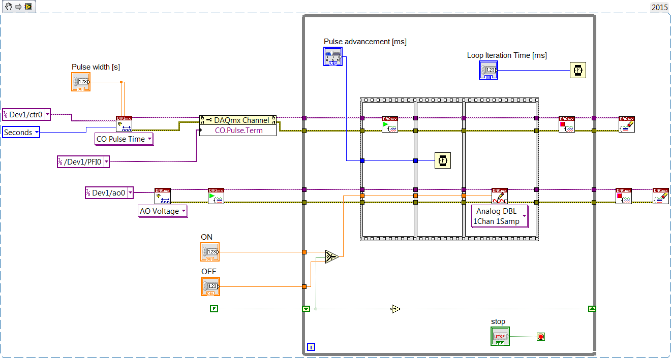
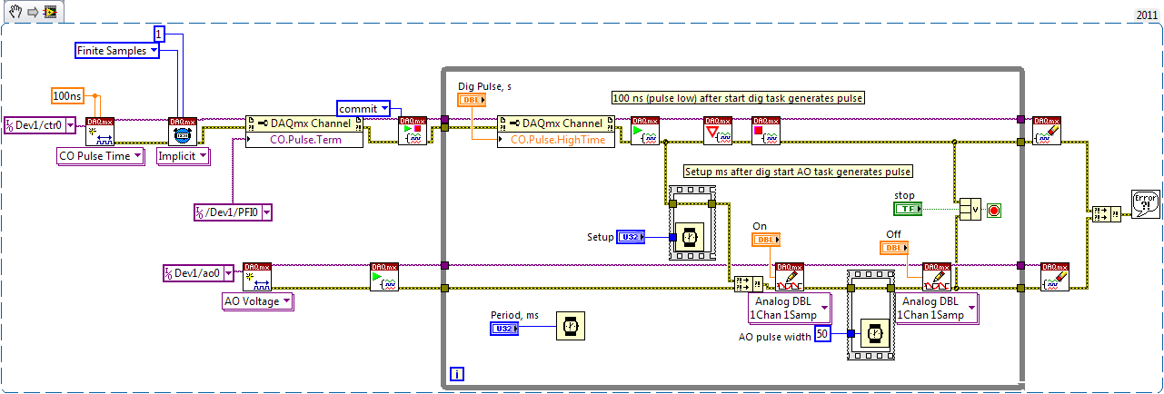
Check the operation of dataflow and single pulse meter output
First counter generates little time, then big time.
Your AO task then is to adjust tension on IT after Dig pulse. After the AO pulse width, he needs to put down
If the Trac software is small enough for you, you might have used USB-6008 ($250), not Xseries $ 1600 - apparently of an overdose. X series can do this work with a void microsecond resolution.
-
count the pulses ttl only on 2 V
Hi I have a problem while I was trying to count a pulse ttl using the DAQ Assistant. The problem can be simple, but I just can't solve that since I'm new to LabView.
There is a TTL pulse produced of our ODA that is about 30 ns width, 5V. I want to use LabView to perform the count of photons. But because of the noise, I want to put a number limit of 2V, so the software one count higher than 2V TTL pulse. But I can't do that. There is no option to set the limit.
And our material is BNC-2110 and PCIe-6323.
Can someone help me with this? Thank you.
For a counter entry, the minimum voltage for logic there is 2.2 volts - a ttl level. And no, you can not adjust higher.
-
How to count the pulses using RIO (FPGA)
Hello
I want to use RIO (FPGA) for counting the pulses produced by a sensor,
but I don't know how to program. can someone help me.
Thanks in advance
CAIX wrote:
Hello
I want to use RIO (FPGA) for counting the pulses produced by a sensor,
but I don't know how to program. can someone help me.
Thanks in advance
Search for example for 'Meter of RIO' finder. There are dozens of examples that should help you.
-
I hope someone can point me in the right direction and also to clarify some concepts!
Background: I am currently using the box USB-6009 and labview on a laptop to output 2 analog waves. It acts as a waveform(0.5-2Hz) of speed (periodic) for an engine step by step (with a driver) to execute a loop of traffic, and the other waveform acts as a signal short 5V to trigger some imaging equipment. The ability to move or to delay the start time of the wave of 'trigger' compared to the waveform of speed in steps of hail (ms) became a requirement for my experiments. Given the time where the USB-6009 case, software based accuracy was not good enough because I need, and the way I wrote the VI limits my delay/travel at the speed of wave deltaT(30-40ms). I started to look at the USB - M series (portability is an obligation) since some have calendar based on the material, and I could send the signal to a buffer rather than iteratively having read every value of the wave in. It also seems that a digital short "pulse" works better than an analog wave form creating any. Where I ran into some confusion is to determine the requirements of a deterministic way sync the two. I am looking for new hardware. I started by looking at the box USB-6211. However, I ran across a few posts talking about the digital I/o correlated being required to perform vaguely similar configurations, which would require something more like the USB-6221. Since I have probably to the digital output to be on a time scale different analog output, is i/o digital correlated required? If not, would the 6211 work?
Just to be clear, I need the periodic waveform and relaxation to be constantly in phase (anywhere, 10 minutes to several hours). Then be able to move the pulse +/-1ms (minimum) and repeat. I can justify the most expensive device if necessary, but I don't want to get something I don't need.
I have attached a figure (not not to scale) of what I am after, in the likely event that my explanation was not too clear.
Thank you
Gabe
Hi Gabe,
The 6211 did not buffer IO digital as some of our other devices. However, there are two complete meters on the 6211 which can be used to perform a generation of pulses (pulse or continuous pulse train - you can output a pulse train using two counters finished). You can take a look at the section Applications of meter output x 621 manual for more information.
What it sounds like, the 6211 will do what you need for the following reasons:
1. the AO of the 6211 lines are buffered and can be clocked up to 250 kHz per channel (in contrast to the 6009 using AO NI by SW).
2 the 6211 counters can be used to generate two pulse based on a basis of time of 80 MHz (12.5 ns pulse width and resolution time). The 6009 does not output meter.
(a) if the two pulses must be on the same line, you must configure a task of generation of pulses finished' (this example uses two meters behind the scenes).
(b) if both impulses are on separate lines, then you can use a task to counter separated for each line with a different initial delay.
The 6211 does not supported clocked generation of digital signals (e.g. 100010101110100) but if you just need to generate impulses so that's precisely what the counters can be used to. I think that's where all the confusion, but seems like the generation of digital signals should not be necessary for your application. Trigger the counter outputs out of the trigger to start AO and adjusting the parameter 'Initial period' should give you what you are looking for. Don't forget to start the tasks of meter in the software before the tasks of the AO (if they are armed and ready to go before the start AO is sent).
I hope this helps, don't forget to post if you have any questions!
Best regards
-
SSI RS422: read digital finished samples off rising Digital pulse
I have to read data from an instrument that uses SSI RS422 communication. I have to pulse the finite number of line N clock of pulses (in any case of update) and on the front of each pulse digital sample ends up compression in a word of size N. A pulse is fine but I can't get my right to sync for playback. Is there a way to trigger the front of this impulse? I checked I get reasonable given by a Logic Analyzer on an oscilliscope so this defintely my approach to reading.
I am using a PXI-6289 and pulsed through ctr out 0.
Here is my configuration of the task
DAQmxErrChk (DAQmxCreateTask("",&readTaskHandle));

DAQmxErrChk (DAQmxCreateDIChan (readTaskHandle, "/ PXI1Slot15/port0/$line0", "", DAQmx_Val_ChanPerLine ""));

DAQmxErrChk (DAQmxSetTimingAttribute (readTaskHandle, DAQmx_SampClk_Rate, freq));
The reminder of the timer
DAQmxStartTask (taskHandle);
DAQmxStartTask (readTaskHandle);
DAQmxReadDigitalU32 (readTaskHandle, DAQmx_Val_Auto, 10.0,
DAQmx_Val_GroupByChannel, data, num_samps, & samps_per_chan, 0);DAQmxWaitUntilTaskDone (taskHandle, 0.001);
DAQmxStopTask (taskHandle);
DAQmxStopTask (readTaskHandle);I ended up fixing this by connecting the clock output to a trigger line by calling DAQmxRegisterEveryNSamplesEvent. A did the trick.
-
Hello
I have a power meter which provide the USB driver and a Labview program to get the data and NI USB-6221. The project I am currently working on the needs of:
1 acquire two signals (inputs of simple tension), pressure frequency KHz
2. acquire a flow signal, the output signal is 0 to 5V pulse, each pulse means 0.4 ml volume. So I use a voltage inflows to count impulses in certain period of time (in this case, 1 S) for water flow. ; KHz sampling frequency and the 1 Hz update rate
3. acquire a signal of engine speed. The output signal is pulse square wave whose frequency is related to the speed. I use a REIT port to measure the frequency. Sampling rate: Auto
4 give output voltage sine or square wave, I use AO do that.output rate: Auto
5 acquiring by VISA electricity meter data. Data update rate: every 50ms
Currently, all the 5 tasks work well separately. But when I put them together, some signals are beginning to hang, for example, pressure signals sometimes give nothing.
Another problem is the data record. I programmed the VI in such a way that whenever I press the button 'save start', he begins to record data and save them in a .cvs file. For some reason, I always get only the data in the first table. Coult someone help me? I download my code as follows
Hello
What I meant by open, write, close. For any type of file you are using.
Open the file, which produces a reference, then put the mention in a registry to offset.
Write data, using the function write (for this type of file) and the reference.
When you are finished, close the file reference.
Writing in the spreadsheet opens, written, close all at once. It is very good for this type of application.
***
The issue of the loop is more general. I would like to say first of all, I want to say that since each loop works on its own, it is own VI, and that this program has put all this into a single VI, which has a method to solve the problem is to disable all the loops and allow them one at a time to see if there is a culprit responsible for.
Using multiple loops executes the code at the same time, and some loops would be cycle faster than others, especially if some of them are loops just as they are.
Communication between the loops is a test to the address if necessary.
Running all these signals through different loops DAQ must also be examined. Don't know what questions are for read and write somewhat randomly in the channels.
-
How to measure width of digital pulse using SMU-6548
Measure the digital signal of high level pulse width (a few seconds)
1US accuracy requirements
Thank you
Hello
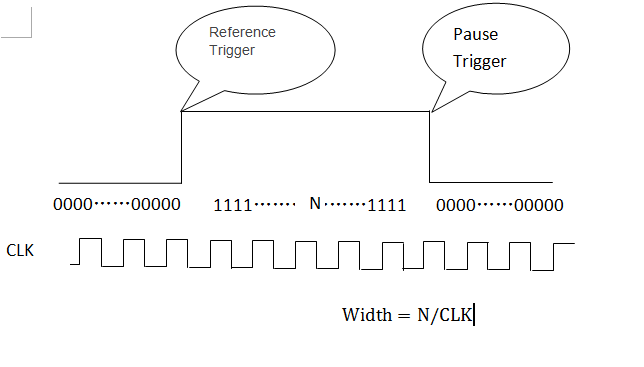
You can configure the trigger of the reference and the break, and you will get a table as below. Calculate the number of 1,
The pulse width is N/clock. -
No count output / pulse pulse does in a meter of pcie-6320
Hi all
IM using pcie-6320 in my application to generate impulses using the counter i/o.Even when I try to generate/counting pulses using MAX, I coundnt find no exit, im watching the e/s using a CRO. My camera works very well and tested hardware DAQ Diagnostic Utility tool in this tool also spent the meter test. IM completely stuck here, if anyone has come across such a problem please help me.
Hello.. I solved the problem. In fact, it was found that the cable between junction box and data acquisition is not properly inserted. In any case thanks for your contributions
-
conversion of pulse analogously in Digital pulse sequence
Hello
I work to detect the peaks in a particular time interval say 'x '. I acquired the analog signals (impulses), as shown in the image here AcquiredPulse of analog card with data acquisition. Before detect the peaks of the pulses of different amplitudes having almost the same period of time indicated in the picture above, I want to convert them in digital or of the same amplitude pulses pulses , so it won't be easy for the detection of peaks process. And after getting what I need to know the time interval between pulses.
Can someone help me with the implementation of the present.
By this Vi, you can convert the waveform
-
count digital events on a counter with pci-6602 with reminder on the CVI
Hello
I use a card PCI-6602 with CVI 8.5 and I need trig on the event.
On each pulse, I received, I need to do some actions like increasing a counter, send a message to Rs232 etc... I want to do no loop by checking that the value of the counter has changed. I would use a reminder to run this code only on the value of edge or a counter event.
My problem is that I don't know what function for this. Is it possible to get an event on a pci-6602?
Thank you
James
It's true. If a earlier without change detection and it works.
Thanks for your help.
-
FPGA to generate the counter and pulse train
Hello
I have some experience with Quartus, but new on the FPGA OR.
I have a PCI-7811R. I'm trying to use it to illuminate sequentially 144 LEDs repeatedly. The duration of each pulse is 480us.
Basically, I need to generate a pulse and generator of a counter to record the number of pulses and, according to this number, select which light is lit.
I designed a pulse generator train based on an example of using FPGAS and added a counter in it. You can see in the attached vi.
My question is,
When I put the I/O node inside loops call single cycle, it can generate the correct pulse. However, when I tried to use the local variable to transfer data from the SCTL and then plug it on another node of I/O, I can't detect the pulse signal when I measured this I/O.
Is there something wrong with my code when I try to transfer the data of the SCTL? Can I also use local variable to transfer the value of counter, because I will need it in the next part.
Thank you!
If you are referring to the wired local variable to DIO2 in your attached VI, the problem is very simple: it is outside a loop, then it executes only once. Put this local variable and the node of IO in a loop and I think you'll get something close to the impulse you expect (although if it is not in a loop of single cycle you will have exactly the same calendar).
Maybe you are looking for
-
Tap the screen stops functioning, turn the phone and the
more and more frequently the touchscreen lost all sensitivity, even rebooting is difficult because the power off of the blade does not
-
Ive already has obtained Microsoft Flight Simulator X is installed with Service packs 1 and 2, but this custom still Ultimate Traffic 2 open
-
"The manufacturer was necessary in order to provide a way to reinstall Windows. "If a set of disks came with the laptop, there is a hidden partition restore (not to be confused with the restoration of the system) you would use to do the clean install
-
PIX 515 no traffic on the new IP address don't block
We have received a new range of ips 213.x.x.x/28 from our ISP. They are routed through our existing entry door 92.x.x.146. The problem:We can not all traffic to the pix on the new 213.x.x.x/28 range.-If we try to ping 213.x.x.61, we get the lifetime
-
can I get his pc and tv at the same time?
I am running windows 7 ultimate with a dell xps 8300 pc. I hung it on my sharp HDTV with an hdmi cable, but cannot get sound if I do the default sound TV. When I do that there is no sound from the computer. Is it possible to configure it so that I ca