Counter the acquisition and generation of simultaneous signals of Daqmx triggered
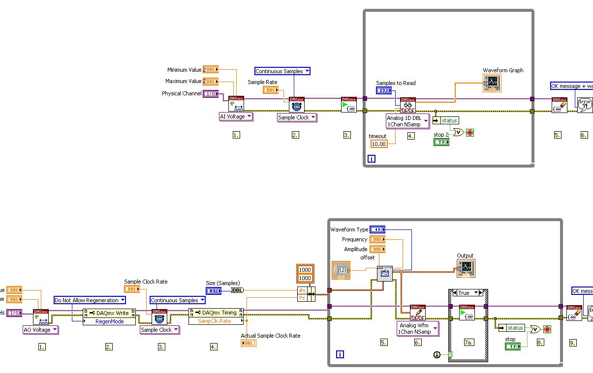
I am writing a vi that collects the data of a specific length (1000 points) when writing the data of the same length on another port on the same card (PCI-6052e). Collection and production are both triggered by a pulse of a counter on another Board (PCI-6711). I am able to trigger both successfully, but not at the same rates and not to the desired resolution. The generation of waves and the collection forms should be 8 msec in duration. I have attached the screws. Any ideas would be appreciated.
Thank you
Jordan
Eventually clocked continuous generation, but the displacement of the wave write vi DAQmx out of the loop (just before the beginning of vi), and this fixed the calendar.
Tags: NI Hardware
Similar Questions
-
Continues RT Acquisition and generation LabVIEW
I was referencing this example for a real-time application, I write:
Continuous acquisition and generation reference example LabVIEW Real-time
http://zone.NI.com/DevZone/CDA/EPD/p/ID/5366
I use the exact code provided. I have run the vi host, configure the target primary vi to the IP address of my computer and HAVE AO point cards on my system. Just like instruced in the comments. The front panel of the host displays my data correctly. Although time is not apear update waveform graph. The program expires correctly after 10 seconds.
The problem is the PDM file. The tdms file created is a stupid idea, nothing coherent when I go to open in Notepad. I see that the code is evaluated at 2.33 out of 5. Y at - it a correction for this code, or a better example to use?
gardma wrote:
The problem is the PDM file. The tdms file created is a stupid idea, nothing coherent when I go to open in Notepad. I see that the code is evaluated at 2.33 out of 5. Y at - it a correction for this code, or a better example to use?
Of course you can not read the file of PDM, you're not a computer

TDMS files are written in binary, so try to read in Notepad will be meaningless.
You need to convert to something readable as ASCII the first
-
Is there a way I can trigger my characters triggers in the world? I want to listen to with him in the obs and be able to do while ingame triggers
Thus, control triggers in CH all streaming a game via OBS (like having your character in the corner and your fullscreen game)? To control triggers CH I believe that enforcement must be active, so I couldn't choose another app/game on PC and press keys to trigger (if I CH running and switch to Photoshop, for example, keyboard triggers will not currently work). But I have not personally tried something like this yet - there must be some sort of solution (2 computers?). I know that we're working on more ways to feed and export your character alive in future versions, so ideally this workflow can be easier on the road.
-
acquisition and generation of signals synchronized redpitaya impetus
Hi, I'm new in collaboration with redpitaya and labview.
I've been trying to get the example of the "generation of signals a synchronized pulse and acquisition" has worked with labview. But I have a few problems.
FISLY, when I downloaded it, some varibles where the wrong type, so connection could not be made (fig. 1). So I use a block converter (from string to number) in order to solve this problem, because he wan't work I changed directly two of the entries from string to number and I kept the conversion of the rest of the string variables (picture 2).
I was getting an error, but the example did not work properly. When I play run, it only resgisted noise, but not the signal that it was created (image 3). I changed the table (chanel I used, amplitude, frequency, the shape of the signal itself)
To check that the wire and the RF input and output was OK I tried to change the signal, put it on my hand and the change in signal to noise, but there was still noise (picture 4). I tried each entry and exit, but I still have the same signal: noise.
To conclude: I can't do this example to work.In addition, I have a question on this example, the labview and Redpitaya libraries: How can I change input 1 input 2 and from exit 1 to exit 2, because I don't see that option 1 of chanel and chanel 2, but it does not say what combination of input and output is. and I can't find the block to edit entries and exits
If anyone has had the same problem, how to solve it?
Thanks in advance!
Entries you 'fixed' are not numbers, looks like they are channel names. The representation has changed some time ago, but it is an example of the former.
Mike...
-
NEITHER USB 6008 AI acquisition and generation of pulse
Dear users of LabVIEW,
Greetings for everyone. I am a beginner of LabVIEW and I have a problem that I solved partially. I would really appreciate your help and suggestions that I searched for days without a bit of luck. The problem is as follows:
I am the acquisition of tension HAVE (continue) 4 to 8 accelerometers. In the meantime, I send you a digital output signal each time when you click on the sampling frequency (i.e. 1000, 2000, 3000,...) If the sampling rate is 1000). In other words, try to send a signal of output digital (at a frequency n Hz) at intervals of 1 second (depending on the material). To make the digital output signal begins to blink a LED every one second. In addition, I need to write signals (voltage) AI and the LED blink timestamps PC (software) separately. All stages of the above are followed in my .vi program, but the real hardware/software level operations kill my timestamps. In other words each LED flash timestamps are not accurate, when I use LabVIEW measurement file express VI (the difference is not at least to the third decimal). In addition, the timestamp is kinda OK when I disable the file LVM write VI. Onemore thing I've noticed is that physically the LED blinks every second two times, I feel it's because of the shift register and loop delay of a second. Is there a way to control the speed of blinking (i.e. Boolean State must change to every 500ms without delaying the inside while loop).
Results and comments:
LabVIEW 2011 .vi, timestamp of files with or without generator of LVM (express VI) files are all attached. Please note that there is a considerable amount of drift in the consecutive timestamps when the file LVM generator is used, on the other hand there are derivative of 0.001 ms when the file LVM generator does not. The reason for horodateurs PC have is about aligning the various measures or observations or events to global time scale.
Please give me any suggestions or help me do at least accurate to milliseconds in VI of witten. Finally, is there any USB DAQ module relatively inexpensive which allows to send an impulse to directly from channel impulse of output digital channels when the "n" sampling frequency Hz is obtained by level of material which could all be accurate, so that the software timer is completely reduced to a minimum. Although there are very material sophistiated of NOR, but our goal of this project is to build and test the system profitable.
Thank you and I really appreciate your time and effort inavluable. Have a great weekend!
Just change the samples to the constant playback at the entrance of the DAQmx Read.vi from 1000 to 500.
Lynn
-
How to make SQL * more count the comment and blank line numbers?
Hello
Parameter Value of the parameter Oracle version Enterprise Edition Release 11.2.0.1.0 - 64 bit OPERATING SYSTEM Linux Fedora Core 17 (X86_64) I would like to know, is it possible to force SQL * Plus to provide the number of the current in the source file line whenever there is an error? I often put in the first line of my script SQLBLANKLINES the VALUE ON that I may be able to put several consecutive blank lines in my code (I do that sometimes, when I find that it is appropriate to make my code more readable or a sequence of instructions which I believe make their logic more comprehensible for the reader of the Group)
Now the problem is that SQL * Plus will ignore these empty lines and whenever there is an error, the line number in the error message does not match the actual line number in the source file, but it seems to be the last non-empty line in the file. Consider the following example:
SET SQLBLANKLINES ON;

DECLARE
    var PLS_INTEGER := 10;
BEGIN


    var := 20
END;
/
In the code above on line 9 (also counting blank lines), there is an error (no semicolon at the end of the var: = 20) but when I run the script
SQL * also, here is the error message I get
SQL > @myscript.sql;
END;
*
ERROR on line 8:
ORA-06550: line 8, column 1:
PLS-00103: encountered the symbol "END" when expected in the following way:
* & = - + ; <>/ is mod remains not rem
< an exponent (*) > <>or! = or ~ = > = < = <>and like2 or
like4 likec between | submultiset of type multiset Member
The symbol ';' was replaced by 'END' continue.
SQL >
As you can see the error message indicates that the error was found on line 8, while in the file, it's really on line 9
As long as the number of lines in the script is limited, this may not be a problem and we can quickly find the actual line number in the code that causes the error, but for a code, including hundreds (or even thousands) of lines and with many comments and blank lines, find line number given by SQL * error message more becomes complicated.
So my question: is it possible to make SQ * more properly draw the line numbers, as they appear in the source file?
Thanks in advance,
Kind regards
Dariyoosh
Hi, Dariyoosh,
The line numbers in error messages are always from the beginning of the statement, but not the file. The back-end which checks the errors and generates the error message, has no idea if this statement has appeared in your file, even if the statement was in a file at all, or if it comes from multiple files, each with its own line 1.
You can divide your scripts into parts, so that the long statements, which may lead to error messages, are each in a separate file, so the statement starts on the line 1 of the file.
For example, you can call a script called fubar.sql, which looks like this:
SET SQLBLANKLINES ON;

@@fubar_1
Which calls another script, called fubar_1.sql, located on the same directory as fubar.sql, that looks like this
DECLARE
    var PLS_INTEGER := 10;
BEGIN

    var := 20
END;
/
You never call him directly fubar_1.
-
acquisition and generation of signals
Hi all!
I'm new to labview and I need help. I am trying to acquire and generate data to two devices simultaneously. I reached successfully synchronous acquisition, but the problem I have is that whenever I run the program it is not compatible. Can someone help me and take a look at my code?
-
Analysis and generation of a signal
Hello
I am using NI Multisim 13.0.I want to generate a signal similar to that illustrated in the accessories acquired using labview that is the output of a phototransistor. The output image contains 10 signals each containing each acquired using 1 k samples and below freq images shows signal components only 1 freq 1 k sample. From the images, it can be analyzed that she has a volatge of 2 DC, 6V, but I'm confused because it contains different frequenices and most (many) frequencies is lying under approximately 1 Hz and some are lying about 135 and 275 to 300 number and very less other frequency components.
What things to take to generate this kind of freq and how to add these types of frequencies to the component continues to generate the signal that will be the same as in the picture shown.
I want to genearte this signal in multisim as this will be used as an input for the design of the filtering step in multisim.
Thank you.
Hi Patangova,
Save your data in a file .lvm in LabVIEW. In Multisim, select square > component, go to the Group of 'Sources', select the 'Signal sources of tension' family, there should be a source of tension of LVM. Drop this part on the workspace, double-click it, and then click the Browse button to load you the file .lvm.
-
line count (*) the amount and add it to the previous of the resulting column
Hello
I'm new to sql and I want to create an additional column which allows to calculate the value of a row in the column number with the rank of its predecessor on the column of the sum. This is the query. I tried to use CUMULATIVE, but it does not serve the purpose.
select to_char(register_date,'YYYY-MM') as "registered_in_month" ,count(*) as Total_count from CMSS.USERS_PROFILE a where a.pcms_db != '*' group by (to_char(register_date,'YYYY-MM')) order by to_char(register_date,'YYYY-MM')That's what I
registered_in_month TOTAL_COUNT-------------------------------------2005-01 12005-02 32005-04 82005-06 4But what I would like to show is less than
registered_in_month TOTAL_COUNT SUM----------------------------------------------2005-01 1 12005-02 3 42005-04 8 122005-06 4 16Hello
So all the ranks of the exit, you want a total cumulative up to and including this line. It's just that the analytical SUM function.
Here's one way:
SELECT TO_CHAR (TRUNC (hiredate, 'MONTH')
, 'fmMonth, YYYY ".
) AS registered_in_month
COUNT (*) AS total_count
, SUM (COUNT (*)) ON (ORDER OF TRUNC (hiredate, 'MONTH'))
AS total_so_far
FROM scott.emp
WHERE job! = "ANALYST."
GROUP OF TRUNC (hiredate, 'MONTH')
ORDER BY TRUNC (hiredate, 'MONTH')
;
I don't have a copy of your table, so I used scott.emp to illustrate.
I like the GROUP BY TRUNC (dt, 'MONTH') instead of GROUP BY TO_CHAR (dt,...) because it allows me to display in any format and always sort in chronological order.
For example, the output of the above query is:
REGISTERED_IN_M TOTAL_COUNT TOTAL_SO_FAR
--------------- ----------- ------------
December, 1980 1 1
February, 1981 2 3
April, 1981 1 4
May, 1981 1 5
June, 1981 1 6
September, 1981 2 8
November, 1981 1 9
December, 1981 1 10
January, 1982 1 11
May, 1987 1 12
Of course, YYYY-MM format works, too.
-
Running the old and new Vcenters simultaneously on the same San
We spend VSphere 4.1 to 5.5. We are very weak with only 3 hosts running about 20 comments of the virtual computer on a San. Our former VM VCenter is always on Win 2003 and I am changing as well.
So instead of doing an upgrade from 4.1 to 5.5 and convert the former vcenter 4.1, we decided to simply fill out a brand new VSphere 5.5 installation to a new server we have. We have also installed a Vcenter 5.5 new appliance as well. So, essentially, we have installed two different vcenter, old and new running. Then, we plan to move hosts esxi 4.1 existing in the new Vcenter device manually. Then eventually fly over the guests of a host in the new box and then wipe and reload each older host with 5.5
So I've already finished the first half of this project. But I have a question.
During the passage of Windows VCenter 4.1 to the new host esx and VCenter Unit 5.5. I run two VCenter (ver 4.1 and ver 5.5) simultaneously for a short period of a few days. We're still running on the host 4.1 old and the new vcenter 5.5 running on the new esx host 5.5.
We will walk a host both the old VCenter and will be added to the new Vcenter 5.5 appliance. But I'll share my SAN alone of course. If I do this and the two versions of VCenter (old and new) running at the same time and sharing my data SAN even stores at the same time, are there problems with it? I don't think so, but I'm not sure.
I installed the first new esxi host and I pointed out to my warehouse of SAN data without any problem. And data warehouses has appeared as they should. But when I add the new host for the new VCenter, as part of the installation process, it displays all relevant San warehouses. I thought it was weird to show during the 'Add host' vcenter. Are there restrictions to running two VERSIONS different VCenter simultaneously on the same data warehouses?
Thank you.
HMorris
You can have multiple instances from running in the same environment vCenter server. What you need to take care of, it's that the ESXi hosts that share the same warehouses not have access to each and other virtual machines (i.e. do not add VMS to multiple hosts). Keep in mind that only VMFS3 data warehouses are available in two versions, do not pass the VMFS data store to VMFS5 when running always hosts v4.1.
> as part of the installation process, it displays all relevant San warehouses
That's ok. When you add a host to vCenter Server it will show that all connected, as well as the VMS data warehouses that are stored on this host.
André
-
measurement and generation of analog signals
Hello
When I try to run this circuit below, it works very well
But when I try to combine the circuit in a loop, just like in the attachment below, the error pop out
Why is - what happened? Is it possible I want to combine the circuit in a loop?
Thank you
Hi Yusof,
Good post. The problem you run in here is that your writing loops must run at least 4 times per second (20kSamples/s / 5kSamples/iteration) while your reading loop should run 10 times per second (10kSamples/s/1kSamples/read). DAQmx writing should determine the speed of loop because it will not write to memory write buffer, there is space. To do this, change to read-1 samples. This tells the labVIEW to read all samples available in the buffer.
Best,
-
Count the edges of the 2 signals TTL (Heidenhain linear scale)
Hi all
This is my first post here. :-)
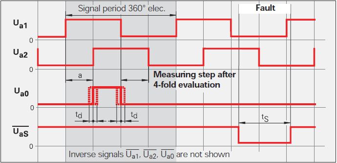
Currently, I'm doing a VI to be used with a linear scale. The linear scale gives 2 TTL signals that have an offset of 90 °. The change in distance of the linear scale is given by counting the fronts and edges of the two signals. See the following image: Ua1 is signal 1 and signal 2 Ua2. You can ignore the other signals.
Now, I want to count the 4 edges in order to translate the 2 signals in the distance. This means that I need advanced two counters for Rising-rising, Rising-Falling Falling Falling, falling on the rise for 2 signals. I tried to do 4 points two counters in LabVIEW but that of course does not work, because an acquisition of data can access the card TTL or I did it wrong.
Once I have to handle this, I also want to understand the meaning.
My card TTL: NI 9402
My electronic Heidenhain interface: 100 IBV (http://www.heidenhain.com/fileadmin/pdb/media/img/598_160-23.pdf - also at the origin of the image)
Hardware configuration: linear scale-> IBV (Elektronic Interface)-> NI 9402-> LabVIEW
Signals: Analog 3-> 3 TTL-> OR 9402
I hope I do not double post. Any help would be greatly appreciated.
I used Heidenhain linear scales in many applications.
As stated in the previous post, the output of your balance is as a quadrature encoder. Therefore, you must use an entry of the DAQ card counter to measure the position of the scale.
The desired X 4 mode is done by the meter itself (not possible with some old maps of OR).
As starting point, see measure angular Position.vi that comes with examples of LabVIEW. On your linear scale, change the type of the polymorphic DAQmx create channel VI CI linear encoder and etiquette of pulses per revolution at a Distance by pulse.
Feel free to post back if you need further assistance.
-
help understand the digital and graphical waveforms
Can someone explain to me how digital waveform working with NOR?
I did a channel physical and wired to a DAQMx create channel then I have it connected to a NSamp of 1Chan ereading Wfm DAQMx and then wired it to a graph of digital waveforms.
I put digital and graphical digital waveform playback in a loop.
When I run it, it seems to me only to get 1 sample on the graph per loop iteration.
The desired output is to add each digital sample as a function of delay which can connected and or scrolls in time to examine what is happening with the signals.
Where is my mistake?
My VI is attached.
Any help would be greatly appreciated!
Also another quick question, is there a 'comment' as a command / / c or ' in VB? Thank you.
Hi Henry,.
Thanks for the post! It seems that you are having problems with the acquisition and the graphic representation of digital data using DAQmx and LabVIEW. You are right that the type of program you have returned a single sample every loop iteration, because you make an acquisition without buffer, timed by the software. This means that the program reads a sample for each channel, whenever the DAQmx reading VI is called, which will depend on the speed of the software will run. In addition, when you view this data, the chart will only display data acquired for this iteration of the loop (that is, in this case, a single sample).
To accomplish what you want will take some extra work and overhead costs in the software, but you can essentially use a shift register and accumulate samples that your program runs. There is a practice done just VI to do this kind of thing with digital signals and is called DWDT Append Digital Signals.vi (this can be found in the palette of functions in respect of programming"Wfm Digital Waveform"). I created a small example which you should be able to run that does this. What actually happens is that the waveform is rewritten each time with new data added in addition to the data passed in. To be able to scroll back and view this data, I turned off automatic scale on the x axis (if it is enabled, it will constantly increase and tries to show all the data at the same time) and selected just a data window to display. In addition, I added a horizontal scroll bar to scroll through the review data.
And to answer your question about the code comments in LabVIEW, this can be done with a clear Structure of the diagram. You will find this structure in your palette of functions in respect of programming' Structures. Using this structure, you can select a part of your block diagram to disable and switch to the active state of wire through the or add different features that will run. Hope this helps and good luck!
-
Combining the scalar output with the acquisition of data time vs RPM
I have no idea why my 9402 NOR does not work as it should, but I don't know he counts the pulses, and at that time I need data for my forthcoming report.
I came to a .vi that contains a very basic way of relating counties in time, however, I need to save the data to an excel sheet for I can analyze it. I have a motor which is connected to an assembly. My encoder measures the rotation of the shaft (no measure of direction availible) which is directly activated by the engine. As load us the assembly, I want to see what the speed of the motor through the encoder. So let's set the engine speed (anywhere from 1 to 100 rpm) and then load the assembly and see if the engine cannot maintain speed. Seems simple but my module is having a difficult time getting one any frequency of the encoder.
Anyway, the .vi I use counts the pulses and divide them by 100 ms once every 100ms. This generates a scalar value that I want to record with regard to the overall time, prefferably every 10th of a second (100ms). I know that I combine the values in a table (2 columns, an indefinite quantity of lines). How can I combine two elements ([time, RPM]) in a table every 100ms and having the table keep expansion of the lines until I hit stop?
Hello Evan
There you go!
Mart
-
What is the difference between the KING and ACQWINDOW regarding the attributes of the camera?
There are two sets of attributes for, left, top, width, and height.
For example, there
IMG_ATTR_ROI_WIDTH vs IMG_ATTR_ACQWINDOW_WIDTH
MG_ATTR_ROI_HEIGHT vs IMG_ATTR_ACQWINDOW_HEIGHT
What are the differences between the KING and ACQWINDOW?
Thank you.
Hi sunspotzsz!
Vision consists of two main steps: acquisition and image processing. IMG_ATTR_ACQWINDOW_WIDTH would the acquisition, and IMG_ATTR_ROI_WIDTH should be part of the treatment. Therefore, if you set the ACQWINDOW_WIDTH to 100 so that numbers all pixels that are acquired will be set to 100, and they will be stored in a buffer. ROI_WIDTH will use an image that is already in memory and 'zoom' so that the only part of the image you are watching / treatment.
Also, take a look at this knowledge base on the Kings: KING FAQ you may find it useful!
Kristen H.
Maybe you are looking for
-
I have already updated Adobe Flash to the latest version, why Firefox may not detect?
Through a company rep IT, he helped to update my Adobe Flash Player already as well as the installation of Firefox 3.6 Now, why the firefox claims "You must update your Adobe Flash Player to view this video" when the Flash Player has been already upd
-
Hi, guys! My iphcone6 is icloud lock and now I can't use my phone, so how do I do?
Hi, guys! My iphcone6 is icloud lock and now I can't use my phone, so how do I do?
-
How can I change the settings in the registry
How do Ichange registry settings
-
I have a Dell with Vista that no longer accepts updates due to a corrupt or missing CBS Manifest.
I try to repair it with the disc of the MFR., and it will not just for the same reason. If I buy a upgrade of Windows7 drive, will I run into the same problem? The system meets the upgrade limit otherwise.
-
ease of installation Windows 10
I am a senior so some of the things in the technical FAQ is not that useful. I would like to please a simple answer to a simple question. 10 Windows will install itself as other updates or I will have to do more than follow installation wizard? I can