measurement and generation of analog signals
Hello
When I try to run this circuit below, it works very well
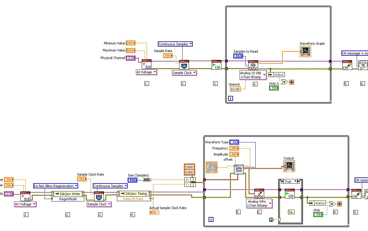
But when I try to combine the circuit in a loop, just like in the attachment below, the error pop out
Why is - what happened? Is it possible I want to combine the circuit in a loop?
Thank you
Hi Yusof,
Good post. The problem you run in here is that your writing loops must run at least 4 times per second (20kSamples/s / 5kSamples/iteration) while your reading loop should run 10 times per second (10kSamples/s/1kSamples/read). DAQmx writing should determine the speed of loop because it will not write to memory write buffer, there is space. To do this, change to read-1 samples. This tells the labVIEW to read all samples available in the buffer.
Best,
Tags: NI Hardware
Similar Questions
-
Generation and acquisition of analog signals simultaneously on USB-6212
Hello, I am novice programmer DAQ trying to create (what I think is) something very simple.
I use a box NI USB-6212 and LabVIEW 8.5 is trying to generate a pulse train analog while recording a simultaneous analog input.
My first question is, is it possible?
Since I'm new to this, I use the DAQ assistant in LabVIEW. I can acquire a signal, I can also generate the desired signal, but I can't seem to operate simultaneously.
I have been successful in obtaining my program to work with both USB-6212, but I have to be able to do this with a single.
I have attached the block diagram and vi, I hope that's easy to answer the question, even if my research so far has left me empty handed.
Any help would be greatly appreciated!
Jon L
Hi Jon,
Well, first of all welcome to the DAQ programming! I took a peek at your code and published it with a device simulation very well, so I ran with the PCI 6251 card in my computer and he did not also get errors. Could you post the error code you get?
If I could figure out what is your error, I would say you encounter errors of buffer because it is too much overhead in the DAQ to wizards in the face of data rates. My suggestion would be to use the example called "Multi-Function Synch AI - AO.vi. This program can be found in the Finder for example of NOR (see Help"find examples in LabVIEW). "" It appears in the input and output material"DAQmx ' synchronization ' Multi-Function.
Can you give that a try and let me know how it goes? Thank you!
-
Analysis and generation of a signal
Hello
I am using NI Multisim 13.0.I want to generate a signal similar to that illustrated in the accessories acquired using labview that is the output of a phototransistor. The output image contains 10 signals each containing each acquired using 1 k samples and below freq images shows signal components only 1 freq 1 k sample. From the images, it can be analyzed that she has a volatge of 2 DC, 6V, but I'm confused because it contains different frequenices and most (many) frequencies is lying under approximately 1 Hz and some are lying about 135 and 275 to 300 number and very less other frequency components.
What things to take to generate this kind of freq and how to add these types of frequencies to the component continues to generate the signal that will be the same as in the picture shown.
I want to genearte this signal in multisim as this will be used as an input for the design of the filtering step in multisim.
Thank you.
Hi Patangova,
Save your data in a file .lvm in LabVIEW. In Multisim, select square > component, go to the Group of 'Sources', select the 'Signal sources of tension' family, there should be a source of tension of LVM. Drop this part on the workspace, double-click it, and then click the Browse button to load you the file .lvm.
-
Counter the acquisition and generation of simultaneous signals of Daqmx triggered
I am writing a vi that collects the data of a specific length (1000 points) when writing the data of the same length on another port on the same card (PCI-6052e). Collection and production are both triggered by a pulse of a counter on another Board (PCI-6711). I am able to trigger both successfully, but not at the same rates and not to the desired resolution. The generation of waves and the collection forms should be 8 msec in duration. I have attached the screws. Any ideas would be appreciated.
Thank you
Jordan
Eventually clocked continuous generation, but the displacement of the wave write vi DAQmx out of the loop (just before the beginning of vi), and this fixed the calendar.
-
generation of digital, analog signals read snap SMU-6358
I have two SMU-6358 card and I want to send control signals to my camera and read the analog signals from the device with them.
For the digital control signals, I tried to set up a system where I specify the identifiers of the pins, bring them into arrays of strings - the respective waveforms would be collected in the tables too - and I transfer them to a VI of inputs/outputs multiples that puts digital waveforms for the cards output pins.
I developed this code here, but it doesn't seem to work. I can't understand how I can convert the string and form table wave to meet the requirements of the input/output VI or which another VI I could use to do the job. Or is there a smarter way to do it?
Thank you
Kriváň
Dear Kriváň
Please find attached the VI in LV 8.6 format. Also, I HIGHLY recommend to rearrange the front panel and which makes it neater, your code is very hard to read and not structured at all. I hope this helps!
-
acquisition and generation of signals synchronized redpitaya impetus
Hi, I'm new in collaboration with redpitaya and labview.
I've been trying to get the example of the "generation of signals a synchronized pulse and acquisition" has worked with labview. But I have a few problems.
FISLY, when I downloaded it, some varibles where the wrong type, so connection could not be made (fig. 1). So I use a block converter (from string to number) in order to solve this problem, because he wan't work I changed directly two of the entries from string to number and I kept the conversion of the rest of the string variables (picture 2).
I was getting an error, but the example did not work properly. When I play run, it only resgisted noise, but not the signal that it was created (image 3). I changed the table (chanel I used, amplitude, frequency, the shape of the signal itself)
To check that the wire and the RF input and output was OK I tried to change the signal, put it on my hand and the change in signal to noise, but there was still noise (picture 4). I tried each entry and exit, but I still have the same signal: noise.
To conclude: I can't do this example to work.In addition, I have a question on this example, the labview and Redpitaya libraries: How can I change input 1 input 2 and from exit 1 to exit 2, because I don't see that option 1 of chanel and chanel 2, but it does not say what combination of input and output is. and I can't find the block to edit entries and exits
If anyone has had the same problem, how to solve it?
Thanks in advance!
Entries you 'fixed' are not numbers, looks like they are channel names. The representation has changed some time ago, but it is an example of the former.
Mike...
-
Problem when the PWM signal combinning and analog signal TOGETHER!
Hello everyone,
first I DAQmx 6212, and I need to run the water pump small (9V - 16V) that should be driven by a PWM signal; I also have a motor (5V - 13V) for a water supply which must be controlled by an analog signal and it has built in a force feedback potentiometer, I logged onto this potentiometer correction + 5V the DAQmx and used the output voltage of the third extremety as a value to diagnose to know the position of the engine.
My VI shows:
1 is a normal meter production to create my PWMout signal.
2 is an analog input, I use it as a PWMin to the LabVIEW to diagnose what is happenning in my pump water through the cycle and frequency.
3 is an entry of the third extremety of the analog potentiometer.
4 is an analog output that I used as power supply of the motor valve and I used an AC/DC amplifier for aplify signal the DAQmx and the motor road, between the two (3. 4.) I made a comeback with a few calculations, I had a P-controller to know the real position of the engine valve.
My problem:
When setting to 1. and 2. in the same VI only, I get an own PWM output with no problem.
also with 3. and 4. in the same VI only i can control the motor valve without any problem.
but when I put all these 4 set found in the attached VI, I have a problem as the engine valve turn continuously without stopping even if I change the position of the valve between 0 and 100%, I should mention that I see a PWM normal outside a signal on my oscilloscope, another thing to delete one of (1 or 2) and run the engine valve VI works fine without any problems.
so this my problem, if you can think of any solution please let me know.
Thanks in advance for your help.
Kind regards
Caliente
Here's your VI, slightly modified so the two analog inputs belong to the same task. This if only for purposes of illustration, I him have not tested. You will still need to do some debugging.
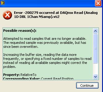
While changing your VI, I noticed another potential problem with your original configuration. You have configured the two tasks of AI for the same frequency, but read you 10000 samples of one of them and only 100 samples from the other (and throw it most of it). Data acquisition data are buffered, and if you read as fast as you acquire, the buffer fills eventually. If you read 10,000 samples of a channel, and the other channel acquires at the same rate, then when you read from the second channel you will get old stale data or an error full buffer.
-
I just installed a diamond ATI TV Wonder HD 750 PCIe on my 64 bit Windows 7 system (it's actually the second tuner card I tried) and still get the same problem. Media Center recognizes the card and both tuners analog and digital, but fails the analogue listening. I get digital very well. I tried to add a channel manually and still no luck. I use cable TV with no cable box and tested the signal on my TV and receive all channels.
I also downloaded the latest Diamond driver and installed all updates more recent windows.
In Media Center, I tried to automaticlly and manually select my signal and each combination, but available with no luck.
Can you please help
Rob
Out of curiosity, what was the 'other tuner"which has been tried before?
Honestly, my recommendation would be to return the tuner (if possible) and get a combo tuner or hybrid that is known to work properly. My first recommendation would be for a Hauppauge HVR-2250 (Council dual combo/hybrid), because it works wonderfully in MC as a tuner NTSC/Clear-QAM of combo/hybrid. MC knows how to treat as what it is, and it works very, very well (I have not one.)
That, or an AverTV Combo G2 (which is not as flexible as the ' 2250, where its slightly lower price.)
HTH,
ChrisMS - MVP (Media Center) [If this post can help solve your problem, please click the 'Mark as answer' or 'Useful' at the top of this message.] [Marking a post as answer, or relatively useful, you help others find the answer more quickly.]
-
Generation of the trigger (or TTL) analog signal
Hello world
Well I look at the droplet, riding on the vibrating bath. In this case I have to synchronize the device with the accelerometers.
Accelerometers are connected to the vibrating plate vibrating sinusoidal with frequency of 80 Hz. I am the acquisition of acceleration using NOR-DAQ USB 6212. A camera (Camera Link Basler, NI PCIe-1433) is used to acquire images of the vibrating plate. The frame rate of the camera is 20 Hz which controlled by external signal (TTL) or camera attributes.
I would like to generate a trigger of data acquisition (signal HAVE) to the camera at the first minimum acceleration in the attachment. I've also attached the file vi. Could if it you please let me know if is there anyway we can generate the trigger of the analog signal.
See you soon
NGO
Hello, NGO,
Can you post the update VI?
-
How to use an analog signal to conditionally generate a TTL (or a square function) signal?
Hello world
I am using PCI-6229 and try to develop a code that can generate a TTL/place function signal from only one analog entry satisfies following conditions: 1. crossing a certain value (for example, 0 V); 2 slope edge of fall. The time delay between the point of passage and newly generated signal TTL/square will be essential to my measurement, and may not exceed 1 millisecond. Any suggestion on this subject? Thank you in advance!
You are using the measure called Excel add-in? That's what this forum is for. Otherwise, you should post to the multifunction DAQ card and speak the language you are using.
-
Common ground for a precise measurement and analysis
Hi all
I wanted your opinion on input and analog output configurations. Connect us two resistors in series and provide an output signal analogue sine through it 10 V. Then, we measure the potential across the two resistors using differential input configurations, on the channels 0 and 1 AI. What I am curious about it is:
(1) do we connect the ground of the analog output and analog input mass together?
(2) if they are interconnected, so am I right in saying that the two potentials measured on the differentialchannel are referenced to a common ground?
(3) that help to improve SNR?
Will be grateful for your responses. (Two resistances here are an example of simulating loads through which am measure potential).
see you soon,
As mentioned, usually GND terminals are connected internally, so there is no real need for an additional connection between the GND AI and AO GND Terminal.
If you connect to them outwardly there is risk of creating a "ground loop", i.e. a closed circuit which cover a certain area that can capture the sounds of the environment. "Double earthing" should generally be avoided. However, perhaps in your configuration you will not see a noticeable difference with or without external connection - but it is evidence that the theory is wrong.
-
How to write constantly to analog output and read from analog inputs
Hi all -
I had a question about writing continuously to analog output reading simultaneously an analog input.
It's my first time to post a message to the community, so please let me know if I made mistakes.
I use Labview 2011 with a NEITHER-DAQ USB 6215.
I'm looking to generate a waveform and write it continuously in an analog output. It is then connected to an entry on the acquisition of data, where I am trying to sample the analog signal. (I realize, there is a system of trivial, but I'm hoping to build on it once I have run).
The task of reading from the analog input works fine, as I tested it in several other cases. I have a problem writing to the analog output.
For this task, I tried to follow the "Gen Cont Wfm Clck Int' VI to generate the wave form and start the task. I then try to write to the output of the analog timed loop. However, it does not seem to transmit a signal and doesn't give me any errors.
I have attached the VI but also a screenshot.
Please let me know if anyone has any ideas. I would really appreciate the help!
Thank you
Peter Borgstrom
We will review your tasks one at a time. First of all, the task of generation/Analog output Waveform. Generate you a waveform (I'm unsure of your VI if it is a fixed waveform or not) and send it to a defined output function to produce a waveform continuously, using N-channel and samples of N (where you set not these previously). You should not put this inside has timed loop, as the DAQ hardware has its own clock - if you simply put it in a while loop (with a stop to break out of the loop), the loop will call the function for the first points of N, wait until all N have been taken out, then call it again to another N points (up to what you press Stop).
Now, suppose that you have the output connected to a load voltage (say a decent resistance). You can wire the input terminals of your A/D converter through the same load and set up a similar analog input loop, running in parallel (i.e. in its own independent of the OD loop, while loop). You pourriez start together (with, say, a merged error since the initialization code line loops HAVE and AO become lines of error in "loops of sampling" described above), but you might want to delay loop (a little) the AI so that the OD has a chance to set the voltage before the bed.
I hope this helps.
BS
-
Question related to the entrance with pci 6221 and SCC 68 analog
I use 6221 PCI and SCC 68 analog read of voltage between the terminals of the drain and the source of a transistor. The drain is at 0 Volt and source is connected to 5 volts via a 100 k resistor. The transistor is used as a follower of the source, and therefore the output is measured at the source of the Terminal. When I measure the voltage by using oscilloscope, I see clearly the change of output as a result of change of voltage of the door. But, when I try to acquire the same by using labview, I see nothing. I tried to change the signal to the CSR, NRSE, but nothing works. Seems to be that something related to differences in impedance. Can you please advice me on this issue? Thanks in advance
Hi rsd111,
I understand that you measure a circuit similar to this ( http://en.wikipedia.org/wiki/Common_drain)
I also get that you use an external power supply with GND connected to the Drain and - 5V connected to the Source with a 100 k resistor.
You should be able to measure the tension between D and S setup a differential measurement and connection Ai0 + D and Ai0 - s, in fact you can youse Ain you prefer.
You should be able to do the same measure also at configuration NRSE linking Ai0 AiSense at the Source and drain.
The Board's input impedance is greater than 10GOhm, it must behave as the oscilloscope in pairing mode high-impedance DC.
6221 specifications: http://digital.ni.com/manuals.nsf/websearch/8117DF4C5A29C95C862573020061023B
Nice day.
-
Output of different analog signals through 4 outputs
Hi all
Exit 4 different analog signals from the PCI 6711 map: I need help. I intend to use the waveform function from the palette of analog generation vi. My goal is to be able to enter the 4 necessary functions, it sampling information and then leaving four available analogue outputs available to the Board of Directors. I saw the code example for the output on multiple lines, but it doesn't seem like he is able to create unique waveforms through the exits, they are all the same waveform. I've attached what I thought work, but I can not get my number of rows in the data to match my number of rows in the task.
Specifically, choose instance polymorphic Analog-> multiple channels-> multiple samples-> 1 D wave.
Your current instance you chose is for just a single line.
-
read the analog signal 0-10 volts of NI6123
I'm reading the analog signal of NI 6123. The range of the analog signal is 0 to 10 volts. This works well when the signal voltage is 0 to 5v (0 ~ 32767). But when the signal is 5 to 10 volts, the value read is always 32767. I also tried the different reading function: DAQmxReadBinaryI32, DAQmxReadBinaryU16, DAQmxReadBinaryU32. The value is identical to DAQmxReadBinaryI16. My OS is windows vista. Here's the part of my codes.
**************************************************************************************************************************************************************************
Create analog data tasks.
DAQmxErrChk (DAQmxCreateTask("",&datHandler));
DAQmxErrChk (DAQmxCreateAIVoltageChan(datHandler,"Dev1/ai0:7","",DAQmx_Val_Cfg_Default,-10,10,DAQmx_Val_Volts,NULL));)
DAQmxErrChk (DAQmxCfgSampClkTiming(datHandler,"",RATE,DAQmx_Val_Rising,DAQmx_Val_ContSamps,RATE*MAXLAS));
DAQmxErrChk (GetTerminalNameWithDevPrefix(datHandler,"ai/SampleClock",trigName));
Create counter tasks.
DAQmxErrChk (DAQmxCreateTask("",&ctrHandler));
DAQmxErrChk (DAQmxCreateCICountEdgesChan(ctrHandler,"Dev1/ctr1","",DAQmx_Val_Rising,0,DAQmx_Val_ExtControlled));
DAQmxErrChk (DAQmxCfgSampClkTiming(ctrHandler,trigName,RATE,DAQmx_Val_Rising,DAQmx_Val_ContSamps,RATE));
DAQmxErrChk (DAQmxRegisterEveryNSamplesEvent (datHandler, DAQmx_Val_Acquired_Into_Buffer, SPLEEN, 0, EveryNCallback, NULL));
DAQmxErrChk (DAQmxRegisterDoneEvent(datHandler,0,DoneCallback,));
Start the task.
DAQmxErrChk (DAQmxStartTask (ctrHandler));
DAQmxErrChk (DAQmxStartTask (datHandler));
In the call back function:
DAQmxErrChk (DAQmxReadBinaryI16 (datHandler, SPLEEN, 3.0, DAQmx_Val_GroupByChannel, data.laser, MISS * MAXLAS, & (data.dataRead), NULL));
DAQmxErrChk (DAQmxReadCounterU32 (ctrHandler, SPLEEN, 3.0, data.counter, SPLEEN, & (data.ctrRead), NULL));
write data to the file.
data.cfile.Write (data.counter, sizeof (int32) * RATE);
data.cfile.Write (data.laser, sizeof (int16) * RATE * MAXLAS);
**************************************************************************************************************************************************************************
Thanks in advance
To make sure that your device is working properly, I recommend first to test the entry in measurement and Automation Explorer (MAX) analog. You can test your device by right clicking on it in the configuration tree and selecting test panels. See if you acquired signal 0 - 10V as you expect. The next step would be to try one of the sample programs that perform a task of analog input. These examples can be found in the start menu > programs > National Instruments > NOR-DAQ > text based code supported. Try an example that does an analog input continues and double bed (instead of binary data not adjusted).
Your program looks good at first so I found nothing that stood out. However, one thing to check is if your function generator (or signal source) expects a 50 ohm or high impedance. This could cause reflections of the signal and cause the device to possibly read a voltage of half of the desired value.
Maybe you are looking for
-
I started a download and the download has stopped, and now I can't reactivate it. The reason why the download has been interrupted was an independent error.
-
Dynamic user LV 2011 events ignore when you're already handling a
Hello I have a UI which fires def dynamic events to control a process. These events are handled in a vi running in parallel. Say that the user has decided to fire an event of 'start', which is handled by the event handler, and now I would like to tha
-
hp15f019dx: remove the missing icon in windows 8.1
I do not have the Remove icon in my taskbar at the bottom like I did in windows 7. How can I get the icon in windows 8.1?
-
Problem with the installation of drivers for HP 650
Hi guys,. Can you help me with this problem. I have Windows 7 Professional installed on my 650 HP and installed all the drivers, but I can't install the drivers for the network, PCI Device controller and SM Bus controller. I tried several solutions
-
error c000021a fatal systrm then 0 x 00000000 (0xc00000001 0x00010037c)
Open windows 7 Dungeon carn can't get repair system recovery I do, but anything said itjust Startup Repair cannot repair this computer automatically