CR1000 Campbell communicate to LabView 8.6
Dear OR engineer.
I want to read the data from a Campbell CR1000 datalogger, and I found this topic (link at the bottom) is useful and perhaps the solution I want. But I can't read Spanish. Can someone help me in English? Thanks and regards,
http://forums.NI.com/NI/board/message?board.ID=6170&message.ID=5278&query.ID=357157#M5278
Hsien
"" Because my goal is just to recover data CR1000 datalogger, I think it's just the CR1000 as a Modbus slave, with good CRBasic syntex, then I can read the CR1000 data by sending a hyperterminal commnd ' \n\r7 '. The following link might be useful to anyone in the future.
http://www.campbellsci.com/forum/messages.cfm?ThreadId=A328967C-0398-DFE2-4AA0FB704E8F93BD
Thank you for your help.
Hsien
Tags: NI Software
Similar Questions
-
Ethernet/IP implicit messaging is possible in labview, PC
Hello
I'm trying to communicate in labview 2011 PC with welder ultrasonic who etherent/ip, for labview real-time data, PC and want to connect data and view graphs
I had installed the EIP toolkit
The welder have
* Message explicit for the configuration of the parameters
I can connect to the welder by explicit messaging, so I had configured settings in welder with EthernetIP ICU get attribute single.vi.
* Implicit message for real-time data, welding
Instance of the entry Assembly: size 101: 12 deformations (48 bytes in total)
Output of the Assembly instance: 102-size: 2 strains (total 8 bytes)
Instance configuration of the Assembly: 103-size: 0 (total 0 bytes)For welding data in real time, I need to communicate but implied message of labview PC.
How to create connectio between labview and welder ultrasound for implicit Messaging.
Hi Emily,.
I'm afraid that you can't create implicit I/O communication between labview and ultrasonic welder.
This is because the driver of the National Instrument is not a scanner, but an adapter (slave) and therefore the position to solder ultrasonic.
This means that we cannot launch an instance of IO. This does not mean the National Instrument driver cannot communicate via e-mail, just that it cannot start this communication.
I know explicit message is not as fast as implicit messaging, but if you are not running transfer limits you can always use explicit messaging.
Explicit messaging speed can reach up to 100 Hz.
Wendy
-
Connect LabVIEW to Schneider Electric M258 Logic Controller (TM258LF42DT4L) error - 1967353901
I was wondering if someone has never connected this particular PLC before LabVIEW. I'm trying to control instruments connected to this API. These instruments aren't NEITHER, therefore they that I could not directly connected to the device via USB, GPIB or VISA. Whenever I have try t connect following this tutorial OR (http://www.ni.com/tutorial/13911/en/), I have an error message to my shared variable.
The possible reasons: LabVIEW DSC: (Hex 0X8ABC8FD3) the I/O modbus server cannot connect to the Modbus Ethernet slave device. Make sure that the slave Modbus Ethernet device working properly and that the connection between the master devices and Modbus slave is configured correctly.
Any help on this approach or suggestion for others would be greatly appreciated.
NOTE: This controller communicates with the CPU I use via a RS485 / RS232 serial port.
SAM
Right, but if the unit will not pass a review of the communication of its native software so it is not really a chance that LabVIEW will be able to communicate with him. I could contact Schneider and see if they can help you make contact with their software, we can worry about communicate using LabVIEW.
-
Exit via LabVIEW tension control
Hello
I'm trying to control an AC output voltage of 0 ~ 250V using LabVIEW, but I could not find any device that makes this kind of operation and can communicate with LabVIEW. All available NEITHER Renault only operate in low-voltage (-10/10V) for the generation of signals. Nobody knows everything power or the method could make this function?
Thank you!
Kenny
Really, you have not used your Google-fu if you do not find a programmable power of ca. Keysight and California Instruments are just two of several suppliers.
-
ADC inforation with UART for Labview
Hello I'm tryin to send a voltage of environ.2 v of CDA on my MCP3903 Board with microchip dspic33f. I am able to communicate with labview by UART, but not able to get the sine wave I hope. I'm not sure how the data are plotted as if just garabage or what. I have attached my code and the image of what is plotted on the graph. IF somone can help me would be great.
-
LabVIEW and Spider8, school project
Heey everyone.
I have a little problem and I hope that one of you could help me with this problem.
I try to get the data of a Spider8 with a laptop equipped with LabVIEW, I do this by using a USB cable to series, instead of a parallel cable.
I have defined this USB to serial as a COM port cable:
[URL =http://img59.imageshack.us/i/devicemanager.png/] [IMG] http://img59.imageshack.us/img59/4613/devicemanager.PNG [LINE] [URL]
Then, I installed the spider8 software. After I tested the communication between the laptop and the spider8 using an altitude sensor, this sensor has an output of 0V to 10V. Communication was perfect between the Spider8 and portable, as you can see below, (I put the probe in channel 0)
[URL =http://img14.imageshack.us/i/spider8setup.png/] [IMG] http://img14.imageshack.us/img14/6200/spider8setup.PNG [LINE] [URL]
Now, I copied the Spider32.dll file and copied in the "WINDOWS\system" and "WINDOWS\system32" directory so that labview can see these .dll files.
[URL =http://img25.imageshack.us/i/spiderdll.png/] [IMG] http://img25.imageshack.us/img25/7715/spiderdll.PNG [LINE] [URL]
[URL =http://img17.imageshack.us/i/spiderdll2.png/] [IMG] http://img17.imageshack.us/img17/7489/spiderdll2.PNG [LINE] [URL]
Now, I used the example of www.hbm.com .vi for attempting to communicate between LabVIEW 8.2 and Spider8. But WHENEVER I try to run this example, I get the following error:
[URL =http://img134.imageshack.us/i/fehler1.png/] [IMG] http://img134.imageshack.us/img134/198/fehler1.PNG [LINE] [URL]
The vi called S8_InitAll is at the very beginning of the program, take a look at the example of HBM blockdiagram:
[URL =http://img269.imageshack.us/i/blokdiagram1.png/] [IMG] http://img269.imageshack.us/img269/2316/blokdiagram1.PNG [LINE] [URL]
When the case structure is false, this vi gives the error:
[URL =http://img143.imageshack.us/i/blokdiagram2.png/] [IMG] http://img143.imageshack.us/img143/6060/blokdiagram2.PNG [LINE] [URL]
It's the S8_InitAll vi: (frontpanel, blockdiagram and "call library" function)
[URL =http://img12.imageshack.us/i/s8initall.png/] [IMG] http://img12.imageshack.us/img12/8415/s8initall.PNG [LINE] [URL]
I seriously have no idea how to solve this problem, whenever I run the example program, I get the same error. I did something wrong with the DLLs from the East - it something else? Please help, thanks!
-
How to control and monitor labview omron plc
Hello
I am able to do to communicate with labview 2009 using plc NOR a CPB and Module DSC server via ethernet, but I don ' t now to control and monitor data Boolean plc from labview.
the machine I use is CPU11 CJ1M Omron CJ1W-ETN21 with. I'm still very new to labview and I hope someone can help me with this and give me some advice on how to proceed. It should also be noted that I can't change the status of the labels directly from NI OPC server itself.
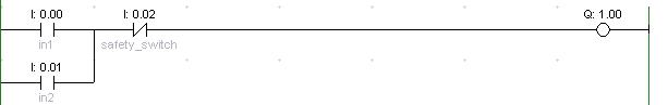
Here is the simple circuit that I would use as a starting point for the control and monitoring of the data of the PLC from labview:
Thanks in advance for the help.
You can read from the entry, impossible to write.
For output, you can read or write.
However, if you have a scale controlling this line out.
There will be a conflict.
-
Problem of Windows vs Mac OS with socket read/write and LabView
Hello
I inherited, multithreaded code, with a singleton that communicates with LabView via few ports/sockets. I don't know (but don't think) mention it in this case multithreading issues, but in case you think there could be a problem. All communications to the LabView through LabView class (instance) singleton.
When we run the code on the same box of MS Windows XP as the LabView so, it works properly; This means that LabView receives orders and the java receives the results. When we run it on a Windows XP box in another room with another subnet it works fine as well. When we run a Mac OS in the same room/network reader.ready () is not true in the time-out period. (see the line of reader.ready () in the original code).
Does anyone know why it would work for Windows but not Mac OS?
A current "guess" what is bad on my part, is that code below (taken out of context, otherwise the position would be really long) needs of some rethinking. Any help/comments/advice on how it is encoded is greatly appreciated.
Here are the existing code.
In particular, I have readLine() in a loop where I catch the exception if it is not read and just keep trying? What is the "best way" to do?// some declarations. long t0, t1; long waittime = 5000; BufferedReader reader; public synchronized void connectCommPort() { if (commportconnected != true) { try { sock = new Socket(); InetSocketAddress endpoint = new InetSocketAddress(IPaddress, commPort); sock.connect(endpoint, 4000); // try to connect with a timeout of 4 seconds. reader = new BufferedReader(new InputStreamReader(sock.getInputStream())); writer = new PrintWriter(sock.getOutputStream()); System.out.println("mec: LabV: SUCCESS - network connection to Labview command port succeeded"); commportconnected = true; errorstatus = false; } catch (IOException ex) { logwriter("LabV: WARNING - network connection to Labview command port failed."+ex.toString()); System.out.println("mec: LabV: WARNING - network connection to Labview command port failed."+ex.toString()); commportconnected = false; errorstatus = true; } } } public synchronized float readpot(int potnumber) { String smotor = Integer.toString(potnumber); if (potnumber >= 0 && potnumber <= 5) { String message = "pot " + smotor; connectCommPort(); if (commportconnected) { try { writer.print(message + "\r\n"); writer.flush(); logwriter("LabV: [sent] " + message); potvalue = potlistener(); } catch (Exception ex) { System.out.println("mec: Exception while sending command "+ex.getLocalizedMessage()); } disconnectCommPort(); } } else { if (potnumber == 7 || potnumber == 6) { potvalue = 5.f; logwriter("Faked pot reading for potnumber " + potnumber); } else { logwriter("WARNING: " + potnumber + " is not a valid pot number (must be 0 to 6)"); } } return potvalue; } public synchronized float potlistener() { String message = null; t0 = System.currentTimeMillis(); t1 = System.currentTimeMillis(); boolean donereading = false; while ((t1 - t0) < (waittime) & donereading != true) { t1 = System.currentTimeMillis(); try { while (reader.ready()) { message = reader.readLine(); logwriter("LabV: [received] " + message); if (message.contains(".")) { potvalue = Float.parseFloat(message); } donereading = true; } // close reader-ready-while } catch (Exception ex) { System.err.println("Exeption in potlistener() "+ex.getLocalizedMessage()); } } // close timeout while loop return potvalue; }
Here's what I thought, something like:while ( ((t1 - t0) < waittime) && !donereading ) { t1 = System.currentTimeMillis(); try { message = reader.readLine(); logwriter("LabV: [received] " + message); if (message.contains(".")) { potvalue = Float.parseFloat(message); donereading = true; } } catch (Exception ex) { System.err.println("Exeption in potlistener() "+ex.getLocalizedMessage()); } } // close timeout while loop(a) No, but I would look into the configuration of the network itself rather than the Java code.
(b) the correct way to enforce a timeout of read is through Socket.setSoTimeout ().
-
Analog value read with DSC Module Modbus
Hi, I have a Delta PLC with an AD converter module. I use the four analog channels and in one of them, I have a thermocouple which displays temperature data on a microprocessor thermocouple meter. However, I want to display the data in Labview. The controller communicates with labview through the DSC Module of labview with success, but I am not able to read the data. Looking forward to your help.
Found the solution. addressing to the modbus master was different for this model of plc, so I looked up the address for delta plc Modbus and the analog read list has been a success on labview.
-
Screenshot on tps2000 series oscilloscopes
Hello
I've been trying to solve this problem for the last days. I have a Tektronixs TPS2024B oscilliscope that uses RS232 to communicate with Labview 8.0 and 2012 (both have the same result). The goal is to get a screenshot using commands on PAPER of Tek. I can reicive a bitmap image, but it's only part of the bitmap and the rest is black. See photo and code below.
You can see the oscilliscope take the paper and there is of course the bytes written to the bitmap of the read buffer. I tried to place delays everywhere to see if that was the problem but nothing helped.
Someone at - it suggestions? Thank you.


Instead of reading 1 million bytes, read a few hundred at a time in a tight loop.
-
Naming of the third-party devices
Hello
I'm quite familiar with the basics of coding Labvew and the handling of the device, but until recently, I've always used decives of National Instruments. I recently installed a computer (USB-202) of the measurement data acquisition and their Labview drivers installed successfully. When I run a question, is that I run 5 different hardware, and I would give them every meaningful IDs, instead of Dev0, Dev1, etc.. I know it's simple enough using MAX, but the Measurment devices are not picked up by Max I tried to rename the devices by using the software provided by Measurement Computing, but it does not seem to communicate to Labview. Is it possible to appoint the devices in a way that recognizes Labview?
Kind regards
A quick update. I implimented the above code and found that it reads the device number (for example Dev0), but does not provide a way of naming the unit of something meaningful. A subsequent appeal found that such an operation was not possible,
-
Hi all
I need to communicate with a machine to send a unique information. This unique information is to provide different sensors that communicate with Labview. My problem is when I start my VI, he stopped 30 seconds with the error code 66. You can see attached a screenshot of the error and my VI. This error that when I use a while loop, if I use the term continually touch the error does not appear.
As a beginner I don't really know the origin of this error. I only know that it can be linked to the respons of time between my computer and the controller.
Thanks in advance for your help
Concerning
Baptist
The model of the automaton is a pro-deal LM 4301
Looks like something is to be constantly opened and closed. You really shouldn't do. You must initialize once before the loop and close once after the loop.
Specifically, this error indicates that the instrument has closed its connection. You make something for him say to unplug?
-
NI-VISA takes a unique I.D. number for each USB device?
Hi all
I'm relatively new to LabVIEW and VISA Toolbox.
When you communicate with LabVIEW and a USB via VISA, VISA shoots a D.I. unique number for the USB device for each connection established?
I have reference: http://www.ni.com/white-paper/4713/en
Kind regards
Bryan
Bryan,
I don't understand what you're saying, so let me rephrase my answer and see that if this may help you - IF your device properly implements the USB standard and has a serial number, VISA uses this serial number. If your device does not implement the USB standard correctly or if it does not have a serial number, VISA will do for you.
If your device has a serial number, the VISA can be used to communicate with it. There are routines that detect and identify VISA devices connected to your PC.
JasonP
-
Hello
I intend to communicate that LabVIEW with a controller to motor through the CAN network by using an adapter USB-PCAN system Peak. I wanted to know if NI-CAN be able to send and receive commands through devices that are not National Instrument (in this case, it will be the USB PCAN-adapter of the system Peak). Can anyone who knows something about this topic help out me please?
We used the PCAN USB with the LabVIEW RIDGE driver provide. I don't think you can use NI-CAN or NOR-XNET to talk directly to the network using the PCAN USB CAN but we use the conversion functions of NI-XNET to convert between the CAN messages and signal/data value and vice versa, and then use the driver PCAN LabVIEW for read/write messages.
-
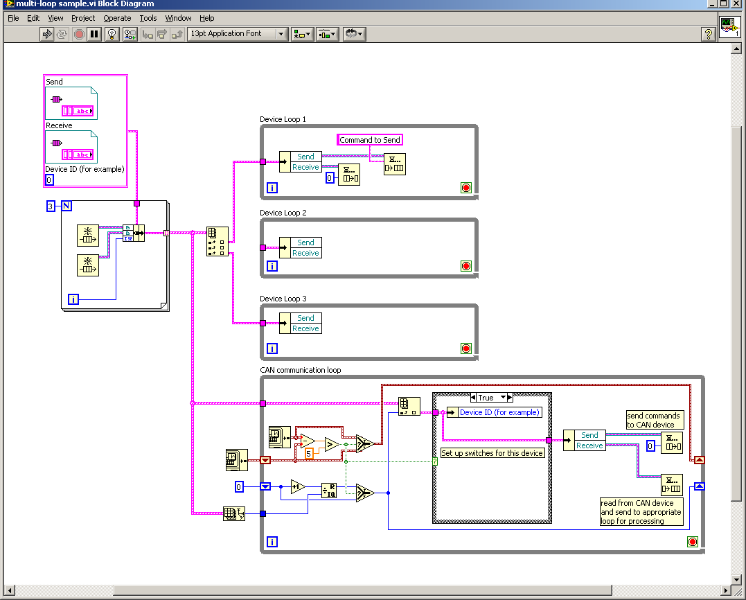
I have three loops that operate independently control the separate devices. I want to their poll continuously for about five seconds at a time. The reason for each device to mark, is I want to communicate to Labview, through a device CAN (8473). Y at - it an easy way to accomplish this question / multiplexing by distribution of task and maintain each independence loops?
Thank you.
Here is a sketch of what I mean. I don't know if there is an example of the expedition which shows this exactly, but certainly there are examples on the use of queues for communication between the loops.
Maybe you are looking for
-
After CTRL + N for the new window, bookmarks toolbar disappears in the new window
When I have a completely, properly functioning window with tabs running with the bookmarks toolbar visible and then I use CTRL + N to open a new window, the 2nd window does not display the bookmarks toolbar. When I go to view > toolbars, toolbar book
-
How to detect the sign of a number?
I output which gives the number of negative or positive. My problem is how to detect the sign of the Boolean number and output? For example if the input number is negative as - 23.11 I want to output the value false and if the number is positive as 1
-
A file of Dc1 appeared in my trash. I tried everything to get rid of him. It says access denied when I try to empty the trash. I have to manually delete the things one by one when I put stuff in the bin. I got hacked or is it an accident that I had s
-
"Away from the taskbar" taskbar and Explorer has stopped working
There is a bug with the taskbar. Here's a video: www.youtube.com/watch?v=qGDVjj93oKA I did a disk cleanup to delete all the thumbs and other things. I also reset some things to clear the messy icons (leave a tutorial to another question on this site)
-
CPIX 4.0 (3) with the TAPS (CCM 4.1 (3))
Hi Forum, I have a problem with the new application of TAPS. Addition of the aar in the repository file work well. The Application is added correct in Applications / application management, but first no Script is associated with the properties of the