Creating a 20 000 hz sine wave
Hello. I have Troubé with the sound on my youtube video download and after a bit of research on the web, I came across a possible solution of mixture in an inaudible sine wave to 20 000 hz to deceive the youtubes audio compressors leaving the audio not transformed. I watched this in hearing less create tone, but I do not know what parameters to change to get sinusoidal signal at 20 000 hz. Could someone tell me how to do what you please?
You just need to type 20 000 in the field of basic frequency and adjust the Volume to dB to what ever you want and enter the length you need. All other settings should be OK, the default value.
Tags: Audition
Similar Questions
-
Ideas on how to create a sine wave between 0 and 10 V with NI 5412?
Hello
I tried to create a sine wave from 0 to 10 volts on a 5412 OR. I have 2 problems and I have a question:
(1) I can't generate a waveform with lag, even when using the examples of NEITHER.
(2) the value of the offset, that I can set the camera is of +/-25% range of amplitudes. Do I have to create an arbitrary waveform myself?
(3) in the brochure it says I can get 12 v peak-to-peak. Does this mean that it is between-6 and 6, or it is between 0 and 12?
I would appreciate it if I could see an example.
Thank you very much.
Hi, several notes:
(1) the peak to peak voltage is 12V. For example, it can operate between 0 - 12V.
(2) the shift of 25% limit is for a given wave. That means assuming that it will create a wave, it cannot compensate for 25% of the beach. The solution is to create an arbitrary wave (e.g. a sine between 0 and 10 V) and the function generator to create rather than attempt to compensate for a sine wave.
Thanks for the help though.
-
Why my output signal is produced waves triangle when I want the sine waves
in labview I use the daq assistant to create an output voltage signal to create a sine wave. When I connect it to the opscilloscope, it reads the triangle waves. is someone can you please tell me why this is.
9172 is a chassis so I need to know the module you use, too. You should try the example:
%ProgramFiles%\National Instruments\LabVIEW 2012\examples\DAQmx\Analog Output\Voltage - Output.vi continues
It shows you how to create a waveform to generate, you could use this piece and feed in your daq assistant.
-
Hi all
I use a card OR-DAQ 6009, and I'm trying to generate a sine wave of LABVIEW 8.5 and then go out to the analog output of the data acquisition card.
The code I wrote was pretty simple. Generate a sine wave with the help of "create an analog signal" and then connect the sine function «writing» DAQmx. The output of the 'writing' goes into the task of "DAQ Assistant" outside of the loop.
But I get the following error message:
Error-200077 occurred to the property Node DAQmx Timing (arg 1) DAQmx calendar (sample clock)
Property: SampTimingType
You asked: sample clock
You can select: on requestParameters with respect to the timing of the sample in each of the 3 components are:
Creat analog signal: sampling frequency: 10K block size (samples): 100
Writing: Analog, single channel, several samples, waveform
DAQ Assistant: sync settings:
Generationg mode: samples of N
Writing samples: 100
Rate (Hz): 10K
Any help will be appreciated.
Thank you.
Colin
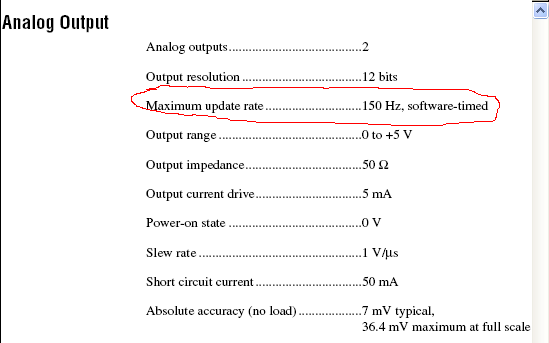
You see this error because the 6009 does not support timed by the material outputs analog. Have you looked at the data sheet of the device? He does not appear. Here it is:
Note that the listed maximum rate is 150 s/s, and it is specified as timed software.
So what you're trying to do is not possible with the 6009. You will need a 6221 or something similar. Make sure that any advice you choose supports analog output clocked by material at a fast enough pace for what you're trying to do.
Edit: I see that Dennis beat me to it!
-
Hello
I have a problem of small labview.
I want to generate a sinusoidal pulse with labview and send it to a pc oscilloscope using my sound card.
I did first VI creates a sine wave and sends it to the pc oscilloscope. Works perfectly.
But now I want to create a sine wave with a single period (second VI). Problem is while the VI blocks if I want a high frequency (I need 10 kHz)
So the VI operates on frequencies low but gives this error with a higher frequency:
"the audio driver or the card does not support the desired operation."
Can someone give a solution for my second VI (creation of sinus with a period on 10 kHz). ?
Thanks in advance!
Jelle
Hello Benje,
The problem / the difference you see is indeed in coding and also in the sound card.
In the example of 'work' you use the VI of Signal to simulate with the following parameters:
-44100 samples per second (sampling frequency)
-Number of samples 10000 (samples per cycle of generation)
In the non-functional example, you specify:
- sampling rate = 1000 * 'Value of frequency control'. This info of sampling should be fixed (for example) to 441000 Hz.
-Number of samples 1000 (samples per cycle of generation)
As a sidenote:
Is there a reason why you used different functions to generate similar signals in the VI 2?
-
Hi guys,.
Sorry I have a very simple problem. But it seems that I am too new to LabVIEW... and / or have no idea. I've tried a few things but nothing worked propperly.
I need to generate a sine wave with the following of the flexible parameters.
f = 0.02 Hz... 10 Hz
Range = 0... 500
Offset of 1500
I would like to see a cursor moving and get off after the sine wave. The parameters should be changed at any time that the generation of the sine wave inside a While loop. If that would work I intend to integrate that in the code I wrote for an Arduino, Makerhub, slavery... The values already referring...
I tried allmost all the generation of singnal live that I could find but nothing has worked. Calendar completely proven on a waiting insid the while...
Frequencies below 1 Hz is the fast cursor again... WTF...

A sinusoidal 1 Hz signal should make the cursor up and down 1 times per second... or am I totally wrong.
Ah... Perhaps another question. If possible, I want to count the period. For example, after 4 times of the sine wave stop all programs.
Any help apprechiated... I work with LabVIEW 2012SP1
First of all, please understand this waveform generating function works. You specify a waveform (amplitude, frequency, etc.) and whenever you call the function, it returns all the wave specified points.
You can set the number of points with the #s of the info of sampling pole control. As you put the function in a loop, each itaration gives you #s number of points (1000 in your case). You always get a sine wave on your cursor because each iteration returns a different set of 1000 points (this is because of the method, the function calculates the waveform).
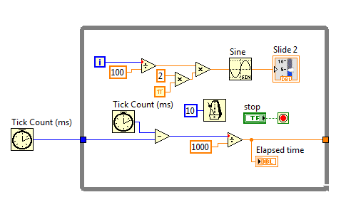
The easiest way to create a sine wave is using the sinus (mathematics, primary, Tigonometric, sine) function. You must use the iteration of the I of the loop counter so that the entry of the sine function. Note that the entry is in radians.
With a little math, you can easily produce and display a sinusoid at 1 Hz.
Kind regards
Adam Boros
-
How to make a sine wave in illustrator?
Hello
I started a thread earlier tonight, but I think I accidentally Pavilion as 'resolved' or something like that (I'm new to this forum). So I'll try this again. I want to know if there is a way to create a sine wave in illustrator. I managed to create a wave of cosine using the on line zig zag effect and choosing "smoothly". But I can't seem to find a good way to do a sinusoidal signal.
That's the difference for those who ask:

I want a sinusoidal signal like the image above.
Thanks for the help!
ekmanch
ekmanch,
If I (put) understand it, to create a single sinusoid full, you can:
(1) create a horizontal line 2.5 times the length of the complete sinusoid desired (or you can adapt the length later);
(2) effect > warp & Transform > Zig Zag 4 grooves by segment and Smmoths Points and height as the size (or you can adapt later);
(3) object > expand appearance.
(4) object > path > add Anchor Points;
(5) with the scissors tool cut where the sine wave starts and ends.
(6) separate if necessary and remove the end bits (and adjust the length/height if necessary).
-
How to make a sine wave with a series of spherical objects (symbols of Yin/Yang)?
How to make a sine wave with a series of spherical objects (symbols of Yin/Yang)?
Do the yin/yang. Shift drag a copy some distance away. Create a blend between the two stages specified. Draw another line. Use the effect > transform > Zig - Zag with enough height and number of steps and smooth anchors. Expand the appearance of the effect. Select the mix and the wide range and the object > blend > replace Spline.

-
Simulate the sine wave using LabVIEW FPGA with NOR-myRIO and display in real time
Hello
I'm relatively new to LabVIEW FPGA. I am trying to test (and later apply) controllers high speed on myRIO.
At this point, I'm trying to simulate the sine wave from 1 to 10 kHz using Sinewave generator VI express. I also intend to display the sine wave on the time real (RT) using FIFO. However, I had a bit of trouble to understaing various synchronization parameters.
1. how to encode information about the sampling frequency generating sine wave? (The side FPGA vi requires only the frequency of the signal and possibly phase and does not rate update lines)
2. how to estimate the number of items in a FIFO? (that is, the relationship between the rate of updates to loop (RT), the signal frequency, sampling frequency and the number of items in the FIFO)
It would be great if we could share a very simple program (side host and target) that did something similar.
Thank you
MILIN
Milot,
I think the problem is the type of data in your FIFO. Your FIFO is configured to use a data type of I16. The problem is the number, it displays only ever will be-1, 0 or 1. To resolve this problem, you must send the sine wave as a fixed point data and convert it to a double on the side of the RT. This should significantly improve your resolution.
-
cwdsp. Sine wave is where the sampling rate?
Hello
According to the method above (CWDSP. Sine wave), the parameters are the following:
(n, a, f, Phase)
n As Variant - [Input] number of samples to generate.
Amp as Variant - [Input] Amplitude of the signal that results.
f As Variant - [Input] frequency of the signal resulting in standardized units of cycles/sample.
The phase as a Variant - initial phase [output] in degrees of the generated signal. Output, the Phase is the phase of the next portion of the signal. Use this setting in the next call to this function to simulate a generator of continuous functions.We are not lack of sampling frequency?
example:
I want to generate the next sine-
FREQ = 1 kHz
sampling frequency = 10 kHz
(Number of samples) block size = 1024
Amp = 1
How will you use this function for this signal?
I think (but I'm not sure of it...) is: CWDSP. SineWave (1024, 1, 1/10, 0)
There is an example: "power spectrum". In this example, they do not mention the sampling frequency and the signal is generated as follows:
CWDSP. SineWave (1024, 1, 0, 1000/1024)
No mention of the sampling frequency.
Thank you
Hey Rafi,
Both of your assertions are correct. The frequency of de.1Hz at no time is the equivalent of what you would get from sampling equipment of a wave of 10 kHz to 1000 s/s; in both cases, you will see a cycle of the wave every 10 samples, as you are pointing out.
-
conditional error for comparison of sine waves
Hi all
I do a small program concerning some changes in the sine waves, and later I compare to set my status. I can't get through this error. I really want to put out as Boolean so my loop condition is attached to this release. Everyone please help
Concerning
Qasim
It's called Convert Dynamic Data type and on the Express > range of Manipulation of the Signal. When you drop on the diagram to a dialog box can be displayed and giving you options regarding the type of data.
Lynn
-
Hello world!
First of all, I use a USRP as a transmitter to emit a sine wave (the signal is exp(j2*pi*f*t)), and then I use the external clock to synchronize the two USRPs (Ref as PPS in are connected to the clock) as receivers. Receivers are in sync, and they are at the same distance from the transmitter, I thought that the signal they receive should have a nearly the same phase. However, in practice, the phase shift is big enough, and this problem really confuses me.
It's the received signals of 2 receivers.
Yes. What you observe is expected.
Near the bottof of this document read the area 'alignment Phase vs Phase coherence '.
http://www.NI.com/white-paper/14311/en/
And also, for the alignment phase, see the following 'Angle of arrival detection with NI USRP '.
https://decibel.NI.com/content/docs/doc-25716
Erik
-
Measure the period and the peak value at crest of a sine wave
Hello
I am new to Veristand and Labview and I was wondering if there is the possibility to do the following:
I would like to measure the period of a sine wave that I capture from analog input of my data acquisition (SMU-6363). Apart from that, I also want to measure the value of crete to crete (Vpp) of the sine wave.
I hope you can help out me.
Thank you.
If the sine wave is of significantly higher frequency than the primary control loop can run... The best way to do it would be to put the DAQ hardware in waveform input mode and use a custom device to read the waveform and perform analyses.
an example is here: requires some labview skills
\examples\NI VeriStand\Custom analysis Devices\waveform -
output signals of the rectangle a PEAK sine wave conversion
Hello
I have a question on the treatment of a PIC16F84 output signals. It seems that the simulation of Multisim does not work properly - but before I blame Multisim, I ask the community NOR or software engineers or a solution. Because I'm German, you are invited to continue this thread in German if it is allowed by the rules of the forum. If you need additional information to analyze my problem, I'll be happy to provide.
The circuit itself has to convert "composition by pulse" signals "tone" (DTMF tones). So you can get old, classic phones work on new devices that do not support the "composition of pulse" more.
The circuit is powered by the analog telephone line current loop line. The PIC is provided by a rudimentary voltage regulation and count pulse signals (voltage failures / power interruption on the telephone line). After that the captain means the series of impulses in their equal number (e.g. 3 pulses = number 3). The captain gives finally two signals with different frequencies to generate a DTMF tone (e.g. number 3 here is 697 and 1477Hz). As you can see in my PDF file attached, it works very well.
Now I have to convert the rectangle wave given by the captain to an at least similar to a sine wave form - otherwise the device that receives the DTMF tones won't understand them.
So I connected a low-pass filter at the output of the PIC. Now, expect the rectangle signal to be smooth in a way as the 'e-function' will (loading / discharging a capacitor through a resistor). But the results are very far from that - as you can see I have very strange curves.
When I implemented a frequency generator with the same output signal as the PEAK and the low pass filter even I get curves as expected.
So we can say that the output of the PIC works like a frequency generator in my circuit. But why does the filter not behave as it should?
I've tried a lot of different values for the parameters of my RC-filter and simulation - this does not solve the problem.
It would be nice if someone has any idea how to solve this problem.
Thank you.
The output impedance of the PEAK may be too high. May be that my car 50 output? Try scaling of impedance of the filter. Do the 10000 ohms resistance and capacitor 10 nF.
Lynn
-
Hello world
This question is perhaps a bit too much, because I have seen already too many messages on SNR and SINAD in this forum. But honestly, I've been looking for all threads and I couldn't find what I really need, that's why I am posting this however.
My question is, how do I get the real analog sine wave SINAD or SNR output PXI-6733. I tried to look at example SINAD base measureand also niScope EX Fetch to always use the PXI-5105, but I don't think I get the real value of SINAD just by simply using the block measure SINAD. I get only 38dB SINAD using the sampling frequency of 1 MHz and 100 k points, by extraction. IM geneating 10 kHz sine wave with PXI-6733 for example Cont Gen Wm-Int Clk.vi voltage.
Any idea what I miss here?
Hi Mystogan,
If I understand you correct, generate you a sine with the PXI-6733 and measure this return signal
with the PXI-5105 and the expected value are reached because you only get measures
round about 50 DB?
The problem might be that in the manual of the PXI-5105 page 7 the SINAD of the device is between 50-62 db.
If you want to get the best result, you must use a map better as the PXI-5122 page 9 the beach is here
89 - 102 db.

Maybe you are looking for
-
Satellite T210-10Z: letters from defective keyboard 'm', 'j', 'u' and the number '7 '.
I just bought a laptop Satellite T210-10Z while in a trip to Europe. The keyboard, however, the doesn´t work fine. The letters * ', 'j', 'u' * and number * '7' * does not apear on the screen after we press one of them.They will apear on the screen, i
-
Bought on credit - charged credit card confirmation received, but no credit on my account!
Hello, I bought $6 credit last night and immediately received a confirmation sms from my bank that my card had been charged, as well as a confirmation of the purchase of Skype. However, my balance is still a bit above $0 and it's as if I had not relo
-
Export slide show to DVD format?
I have a full slide show some images of 96 with music in the background. How do I export it to the DVD format to play on a standard DVD player? I'm on OS 10.11.1 and Photos Version 1.2 (340.4.0) Thank you CB
-
Windows RT will be a desktop computer? If so, what kind of applications will run?
I wonder about windows RT I heard several sources say different things. Windows RT has a traditional desktop computer? If so, here are the ways I think this could work. Can you tell me how it will work? 1. it has no offices. 2. He has a desktop compu
-
Hi all I use a PCI 6503 with a Gecko g320 servo controller. I have control of the engine, except that it is not precise enough. The attached vi is used to send a signal to the controller, which moves the engine. I would like to be able to specify the