output signals of the rectangle a PEAK sine wave conversion
Hello
I have a question on the treatment of a PIC16F84 output signals. It seems that the simulation of Multisim does not work properly - but before I blame Multisim, I ask the community NOR or software engineers or a solution. Because I'm German, you are invited to continue this thread in German if it is allowed by the rules of the forum. If you need additional information to analyze my problem, I'll be happy to provide.
The circuit itself has to convert "composition by pulse" signals "tone" (DTMF tones). So you can get old, classic phones work on new devices that do not support the "composition of pulse" more.
The circuit is powered by the analog telephone line current loop line. The PIC is provided by a rudimentary voltage regulation and count pulse signals (voltage failures / power interruption on the telephone line). After that the captain means the series of impulses in their equal number (e.g. 3 pulses = number 3). The captain gives finally two signals with different frequencies to generate a DTMF tone (e.g. number 3 here is 697 and 1477Hz). As you can see in my PDF file attached, it works very well.
Now I have to convert the rectangle wave given by the captain to an at least similar to a sine wave form - otherwise the device that receives the DTMF tones won't understand them.
So I connected a low-pass filter at the output of the PIC. Now, expect the rectangle signal to be smooth in a way as the 'e-function' will (loading / discharging a capacitor through a resistor). But the results are very far from that - as you can see I have very strange curves.
When I implemented a frequency generator with the same output signal as the PEAK and the low pass filter even I get curves as expected.
So we can say that the output of the PIC works like a frequency generator in my circuit. But why does the filter not behave as it should?
I've tried a lot of different values for the parameters of my RC-filter and simulation - this does not solve the problem.
It would be nice if someone has any idea how to solve this problem.
Thank you.
The output impedance of the PEAK may be too high. May be that my car 50 output? Try scaling of impedance of the filter. Do the 10000 ohms resistance and capacitor 10 nF.
Lynn
Tags: NI Software
Similar Questions
-
Measure the period and the peak value at crest of a sine wave
Hello
I am new to Veristand and Labview and I was wondering if there is the possibility to do the following:
I would like to measure the period of a sine wave that I capture from analog input of my data acquisition (SMU-6363). Apart from that, I also want to measure the value of crete to crete (Vpp) of the sine wave.
I hope you can help out me.
Thank you.
If the sine wave is of significantly higher frequency than the primary control loop can run... The best way to do it would be to put the DAQ hardware in waveform input mode and use a custom device to read the waveform and perform analyses.
an example is here: requires some labview skills
\examples\NI VeriStand\Custom analysis Devices\waveform -
Simulate the sine wave using LabVIEW FPGA with NOR-myRIO and display in real time
Hello
I'm relatively new to LabVIEW FPGA. I am trying to test (and later apply) controllers high speed on myRIO.
At this point, I'm trying to simulate the sine wave from 1 to 10 kHz using Sinewave generator VI express. I also intend to display the sine wave on the time real (RT) using FIFO. However, I had a bit of trouble to understaing various synchronization parameters.
1. how to encode information about the sampling frequency generating sine wave? (The side FPGA vi requires only the frequency of the signal and possibly phase and does not rate update lines)
2. how to estimate the number of items in a FIFO? (that is, the relationship between the rate of updates to loop (RT), the signal frequency, sampling frequency and the number of items in the FIFO)
It would be great if we could share a very simple program (side host and target) that did something similar.
Thank you
MILIN
Milot,
I think the problem is the type of data in your FIFO. Your FIFO is configured to use a data type of I16. The problem is the number, it displays only ever will be-1, 0 or 1. To resolve this problem, you must send the sine wave as a fixed point data and convert it to a double on the side of the RT. This should significantly improve your resolution.
-
Generate a digital output that indicates the frequency of half of the contribution
Hi, I'm new with data acquisition. I would like to get your help.
I have a digital signal input that is generated by an encoder. I would like to generate an output signal of the way that his level of signal will change at each edge of the awareness of the input signal so that the frequency is half that of the entry.
I would like to know how to do this using the NI DAQ M 6221 map.
Thanks for your help

Hardware solutions can be so simple... sometimes I prefer an iron solder wire

Look at the section counter...
I think there's a prescaler/separator for the meter... and the next would try to drive the output to a PFI
-
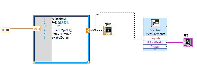
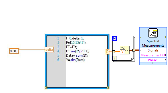
How to display different sine waves in a table and do a fft of these and display them in a chart?
How can I cannect my mathscript output SIgnal of VI entry spectral measures. I have a problem since the release of the mathscript "D" file is 2D DBL. I don't know how to convert such data in order to be logged at the entrance of the signal of the VI of spectral measures. I also want that the waveform graph connected to the output of the VI measures spectral, display the FFT of three sine waves in a chart.
Do not connect. Just go to Forloop.
-
How to take a derivative of a sine wave?
I know this is probably very simple and I'm sure that I'm doing something stupid, but please could someone help me... I'm just trying to draw the derivative of a sine wave on the same graph as the original sine wave. There seems to be working (it shows a cosine wave), but the magnitude is far away. Please could someone just point to me why the amplitude is off... the original sine wave going between 1 and -1, but the derivative is between 60 and -60
Just speculating, but...
- The derivative of a sinusoid of 10 Hz should have an amplitude of ±60 remarks (2 * pi * 10).
- The VI of sinusoidal waveform has a default frequency of 10 Hz.
Coincidence?
Best regards
-
Why my output signal is produced waves triangle when I want the sine waves
in labview I use the daq assistant to create an output voltage signal to create a sine wave. When I connect it to the opscilloscope, it reads the triangle waves. is someone can you please tell me why this is.
9172 is a chassis so I need to know the module you use, too. You should try the example:
%ProgramFiles%\National Instruments\LabVIEW 2012\examples\DAQmx\Analog Output\Voltage - Output.vi continues
It shows you how to create a waveform to generate, you could use this piece and feed in your daq assistant.
-
Hello world!
First of all, I use a USRP as a transmitter to emit a sine wave (the signal is exp(j2*pi*f*t)), and then I use the external clock to synchronize the two USRPs (Ref as PPS in are connected to the clock) as receivers. Receivers are in sync, and they are at the same distance from the transmitter, I thought that the signal they receive should have a nearly the same phase. However, in practice, the phase shift is big enough, and this problem really confuses me.
It's the received signals of 2 receivers.
Yes. What you observe is expected.
Near the bottof of this document read the area 'alignment Phase vs Phase coherence '.
http://www.NI.com/white-paper/14311/en/
And also, for the alignment phase, see the following 'Angle of arrival detection with NI USRP '.
https://decibel.NI.com/content/docs/doc-25716
Erik
-
Change the shape of the output signal without initializing the new process of output signal
Hello!
How to change the shape of the output signal produced on the output channel without initializing the new process of output signal?
Thank you
Yes, you can do the same thing without count/killing the task all the time.
Attached VI shows how to use redeclenchables AO in the same way, using a meter like time base for the AO.
Please note that attached VI uses the same Subvi as in the example you posted before.
Christian
-
Develop the analog output signal
Let me start by saying that I am a new user of LabVIEW. My experience with LabVIEW is limited to a briefing in which we covered documents in the guide, «Introduction to LabVIEW and Computer-Based measurements» manual the customer Hands-on With regard to what I'm trying to accomplish:
I'm using LabVIEW 8.6, OR cDAQ-9172 and number of NI 9205 and NI 9264 module. I have a load cell that requires a constant supply of 10V to operate. I don't know how to generate this signal or the signal in mV, which is removed from the load to the cDAQ-9172 cell. I tried using DAQ-Express for entry and exit signals. Once I have created two assistants DAQ, I'm not sure what to do next. In addition, the load cell has four sons: green, white, red and black. Green = + GIS, red = + EXC, white = - GIS and black = - Exc. The Red wire is connected to ao0 and the black wire is connected to the COM of NI 9264. the Green wire is connected to ai18 and the white wire is connected to the NI 9205 module ai26.
Any help on this is greatly appreciated!
Yatsco
Hello Yatsco,
Fan of the crows is correct that you would be more successful using a NI 9219 instead of the combination of the PCI module, HAVE / AO. However, it might be possible to use the modules, you should use the load cell, that you try to use, but we need more information on the sensor to say with certainty. A link to form would be preferable.
Assuming that everything would work out with the sensor itself, I would do something like the following:
- Configure your analog output DAQ Assistant for output on the 9264 ao0, leave all default settings except for the generation Mode, you should change it to 1 sample (on request).
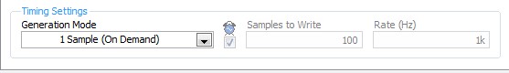
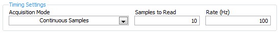
- Configure your analog input DAQ Assistant enter ai18, keep all the default settings again except for sync settings, which should resemble the following:
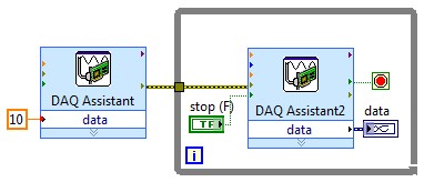
- Your drawing should look like this:
If you do this and you encounter problems with your sensor or its response after the datasheet (or at least the manufacturer and part number), and I'll look into it further.
- Configure your analog output DAQ Assistant for output on the 9264 ao0, leave all default settings except for the generation Mode, you should change it to 1 sample (on request).
-
express the signal voltage AC (sine wave) to form the Phasor
Hi, engineers, is anyway in Labview that I can express an alternating voltage (sine wave) in the form of Phaser? Thank you. Please see this link for background information:
http://en.Wikipedia.org/wiki/file:Unfasor.gif
I have not used it myself, but try this: http://zone.ni.com/devzone/cda/epd/p/id/2982
-
cwdsp. Sine wave is where the sampling rate?
Hello
According to the method above (CWDSP. Sine wave), the parameters are the following:
(n, a, f, Phase)
n As Variant - [Input] number of samples to generate.
Amp as Variant - [Input] Amplitude of the signal that results.
f As Variant - [Input] frequency of the signal resulting in standardized units of cycles/sample.
The phase as a Variant - initial phase [output] in degrees of the generated signal. Output, the Phase is the phase of the next portion of the signal. Use this setting in the next call to this function to simulate a generator of continuous functions.We are not lack of sampling frequency?
example:
I want to generate the next sine-
FREQ = 1 kHz
sampling frequency = 10 kHz
(Number of samples) block size = 1024
Amp = 1
How will you use this function for this signal?
I think (but I'm not sure of it...) is: CWDSP. SineWave (1024, 1, 1/10, 0)
There is an example: "power spectrum". In this example, they do not mention the sampling frequency and the signal is generated as follows:
CWDSP. SineWave (1024, 1, 0, 1000/1024)
No mention of the sampling frequency.
Thank you
Hey Rafi,
Both of your assertions are correct. The frequency of de.1Hz at no time is the equivalent of what you would get from sampling equipment of a wave of 10 kHz to 1000 s/s; in both cases, you will see a cycle of the wave every 10 samples, as you are pointing out.
-
Best way to send signals between the two screws
Hi all
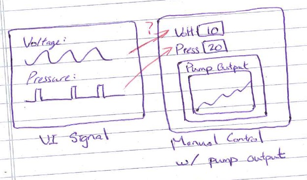
I have two screws that generate some complicated signals (sine wave, pulse, etc.). The other one takes manually entered the tension and pressure send to certain material with a pump and reads the output of the pump.
What is the best way to send the waveform of the signal VI the VI hands-on? I still need to be able to control the signals manually in this manual control VI.
Thank you.
Your user interface would handle this. If you use a machine to States (hint-hint) you would simply chose the State appropriate for your current configuration. You would provide a mechanism (UI, configuration file, argument of command line to name a few) for the parameter which mode to use, and the application would have chosen the appropriate action.
-
Generating analog output signals 4 with different frequencies
Hi all
I was trying to say to generate 4 different signals at different frequencies
1. first waveform is a sine wave with 5000 Hz,
2. other with 8000Hz,
3. third, one is a square with 25 Hz waveform and
4. fourth one with triangular waveform 50 Hz
all waveforms must be generated simultanoeusly.
I tried to generate with the task unique analog output and sample clock (clock rate is 100000). Cross in scope that I see only 5000 and 8000 Hz we generated correctly and the rest two waveforms show the incorrect frequency.
I guess that's due to the frequency of high clock to sample for more low frequencies for ex 25 Hz and 50 Hz. If I reduce the clock rate to get the lower frequencies properly so I can't generate frequencies higher correctly. (there's a clsh between frequencies and the clock frequency)
Is it possible to use DAQ board master sample clock and its magnitude downward revision (everywhere where it is necessary for each waveform separately) to generate all the signals at different frequencies at the same time in a single task?
-
Is it possible to change the sine wave 'exit' a simulation device?
I work on a LV collection and analysis VI in LabView that interfaces with a CDAQ-9178 loaded with 9215 modules/a. chassis. In the Measurement & Automation Explorer, I was able to set up simulated devices that work with my code and I get the sinewave / 5 (?) standard signal noise %.
However, to really test my application, I need a slightly different sine wave with high frequency (1-10 Hz vs the)<1hz sent="" by="" the="" simulated="" device). ="" is="" there="" anyway="" to="" modify="" or="" get="" the="" simulated="" device="" to="" output="" a="" different="" wave? ="" if="" not, ="" are="" there="" any="" other="" simple="" ways="" to="" simulate="" the="" device? ="" i="" could="" write="" another="" vi="" to="" send="" out="" a="" sinewave="" but="" was="" looking="" for="" a="" more="" obvious="" or="" simpler="" solution="">
Thank you
# You need to do is call an of the generating functions of waveform instead of the DAQmx Read. Place inside a case, the declaration or the conditional structure disable is fairly simple.
Maybe you are looking for
-
I'm so glad on 2 series watch and have already ordered. My question is: I do aerobics and wonder how the watch can handle this. Does anyone have an idea?
-
Warranty period for Pavilion g6-2301AX
Hello I bought this hp Pavilion g6-2301AX only today, the product comes with one year warranty. But when I check-in to see the guarantee of update on hp support assistant it shows: Standard warranty beginning 25/04/2013 Date of end of standard warran
-
How to extend the volume of data in the Windows XP machine?
Victorinox original title: space Partition: My C drive is almost full (110 MB only free) but my G, E, H readers have at least 23 GB of free space in each of them. SO can I do anything to divide the sapce. I know that to do something with the start me
-
Installed Vista Home Premium twice!
Hi, I lost all my data at one point and had to start from scratch. I think I've installed windows two times because each time I start up I have to choose between 'windows vista' and 'windows vista '... I was chosen the first of all time, but I think
-
Hello After windows has failed and recovery disks has failed, failed on the second disc. If I erased the hard drive using killdisc active and used the recovery disks (made at time of purchase) what are the chances if you work or can we buy HP recover