Creation of 1 d-Array permanently FFT
Hey guys,.
Im making measurements of vibrations with an accelerometer on my mydaq. I already get my timesignal reading properly. Subsequently, I record these readings in a 1 d table. Now, I want to achieve a FFT spectrum.
But the illustrious FFT's are useless, they do not display something useful. I tried before to take a FFT is the express.vi and it worked perfectly. Has obtained Spectra as normally and worked well. But as Im not allowed to use the s express.vi in my project I can't use it.
So, any help would be very appreciated Im getting nuts with him and Im trying to get this race for 3 days...
Thank you very much
LabView 2014
Configure the Read DAQmx for samples of N. reglez_ to return a data type of waveform. Connect to your fft function.
Tags: NI Software
Similar Questions
-
Sampling rate - too much data points
Hello community,
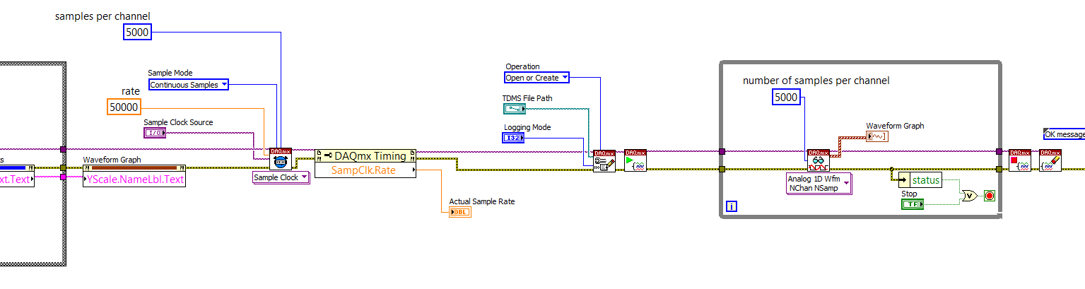
I use a sensor signal strength of pressure on DAQmx labview through 2014. My rate from the hardware synchronization function is 50 KHz. The samples per channel of timing and read screws are the same set to 5 Khz when the channels are a continuous sampling. The problem I'm having is that when I run labview for a few seconds, say 5 seconds, I'm half million points of data. I tried to run for 10 seconds and points were more than a million where it is difficult to analyze. I think that the vi generates too much data points and the buffer is large. Am I wrong? Can you please help me solve this problem?
Kind regards
Mike
You are now ready to learn a little of the power of LabVIEW and data flow programming. LabVIEW is an inherently parallel language - two loops can run independently and in parallel, allowing you to make time-sensitive (such as sampling data) and a lot of time (such as data logging and tracing) at the same time, using queues to pass data between the loops and ensure the buffering required.
If you open LabVIEW and click on the file menu in the toolbar, and then select new... (the points are important!), you will be able to create new ones (VI) from the model. Choose a Framework, Design Patterns, producer/consumer Design Pattern (data). It's what you want to do.
You basically set up a "pure DAQ Acquisition Loop" (without logging TDMS) as producer, creation of 5000-element arrays of data every tenth of a second (if you are sampling at 50 kHz). You create a queue of data outside the loop of producer whose elements are an array of 1 D of waveforms (the output of your Read DAQmx) and instead to send the data to a waveform graph, you put it in the queue.
You are under this loop, a parallel loop that gets the same queue and remove items. This loop will be sitting idle (no time taking CPU) until the data is queued. He then it takes away the poster and registers (logs) in a PDM file. Either way, you should open the TDMS file before entering this loop (consumer), write to the file inside the loop and close the file when the loop exits. Study the example of the VI, you create with the model and see how it works.
The beauty of this is that you can certainly 'keep up' with the writing of the data points in a TDMS file to 50 kHz. You might not be able to display all the points, but there is nothing to prevent you from data processing (by, say, decimating or "block average" it) to a more 'user-friendly' display (your eyes ' sees' a 50 KHz signal?) -you have a set of 100 msec prior to the next package arrives in the queue. Also note that the loop of producer probably takes very little time CPU - most of the time the material is waiting for its clock to 'tick', collection of points in a buffer, then transferring to the loop.
Now you can have your cake and the computer display, too.
Bob Schor
-
I'm pulling my hair out here... I hope someone can help to guide me in the right direction. I'm just learning binary and hex, so please forgive me (and correct me!) if I say something wrong. I have to give credit when it is deserved, because I use info from a post on theautochannel.com to drive this development.
I try to control a small indoor RC helicopter using LabVIEW and a USB joystick. I communicate with a transmitter wireless via rs232 (TTL converted), the Protocol is 125000, 8n1. Each image is 14 bytes 2 bytes of header. I would like to transmit data PPM (pulse position modulation) which is actually just a 10bits (1024 possible measures) range that dictates the position of the servo, for each channel.
Byte 3 & 4 are channel 1, byte 5 and 6 are channels 2, 7 & 8 CH 3,... and so on until the bytes 13 & 14 which is CH 6.
Each pair of bytes begins with "00" (binary).
Byte 3 & 4 should look like "00 00 00 xx xx xx xx xx", where the first "00" is the header, then "00 00" is the identifier of the servo, and 'xx xx xx xx xx' represents the position of the servo. The identifier is actually integrated in the position of the servo, the bits serve a double purpose.
That's why it all will look like this:
CH 01:00 00 00 xx xx xx xx xx (position has a valid range from 0 - 1023)
CH 02:00 00 01 xx xx xx xx xx (range 1024-2047)
CH 03:00 00 10 xx xx xx xx xx (range 2048-3071)
etc... If you convert the binary range, you can see how the second half of the bits ID servo are provided by the range of servo.
I intend by entry VISA to send every byte to constitute the entire frame, and then I will pause ~ 10ms between frames. However, my question is how the hell should I code this? !! I think I need to write, take 1 CH for example, bytes 3 and 4 together into a string and then split them back hand to be sent as two distinct bytes. However, I do not know how to mix my header and the first two bits of my ID servo, which is binary '00 xx', with my servo position (which I know I can write in decimal form, as entry VISA will convert it in binary). Any thoughts on the best way to do so, given all this?
An empty string character likens to a binary "0"?
Has totally confused everyone? I really hope not, but I'm pretty tired so let me know if I need to simplify my question. I hope someone can enlighten me as to the best way to combine the binary constant w modification of decimals (or hex). And if anyone has thoughts about a good way to organize my vi together, I understand that too! Right now I'll just use the structures of sequence... I post my code but at the moment, there is not much to look at
Thank you very much!!
No, you do not confuse everyone, but I think you might have confused yourself.

You basically need to do is to create the array of bytes that will be sent, and then use the array of bytes to a string, so you can send it to the serial port. The creation of the byte array can be done in several ways. You deal with 6 16-bit numbers, of which the lower 10 bits are the values of the position of the servo. I don't know what you want on the front panel to look like, but if you have 6 separate (one for each servo) controls with each set having a range of 0 to 1023 (for 10-bit), then you just have to OR each value based on the number of servo. Put all this in a table, add the bytes of the header and the array of bytes to a string allows to get a string that you can send via the serial port. You can also do this in a loop. Joined a VI to show the two concepts. You have not indicated what version of LabVIEW, is 8.2 you use.
-
Total capacity of the JBOD is not displayed
Hi people,
Only, we have installed ESX on a new Sunfire x 4170 server and connected with a Sunfire JBOD 4200 with 12 TB of capacity. We installed the adaptec disk utility to create RAID 5 and set it to build / check the status.
Now when I do a fdisk - l disk/dev/sdc shows 9 to, however when I create a VMFS file system partition, it takes only 2 TB.

I used the vmkfstools command to create a file vmfs3 system and it shows 2 TB.


Any idea on what he may be wrong with my setup?
Thanks in advance!
You can create extensions, but Bein that it is indeed similar to the creation of a RAID0 array, you loosed on LUN you will lose all your data. It would make more sense to create a single JBOD and slice in the dimensions more suited to your needs, calculate your VM disk needs and create your lun sizes appropiately. If you store all your VMS; s on a single LUN you risk locking of SCSI with be serverly degrade the performance of your infrastructure
If you have found this device or any other answer useful please consider useful or correct buttons using attribute points
Tom Howarth VCP / vExpert
VMware communities user moderator
Blog: www.planetvm.net
Writer on "[vSphere of VMware and Virtual Infrastructure Security: securing ESX and virtual environment | ]. http://www.Amazon.co.UK/VMware-vSphere-virtual-infrastructure-security/DP/0137158009/ref=sr_1_1?ie=UTF8&s=books&QID=1256146240&SR=1-1]'.
-
FFT (up to harmonic (n) of the 2D array
Hello 150,.
I want to record a FFT for the specific frequency range. The entrance is a 2D table in which each row represents a record. I just need phase und amplitude of the harmonics (up to the n - controllable). I didn't need too many harmonics, so I would avoid calculations and do to the amount of certain frequencies in the FFT.
I would take this VI, but y at - it an option to set a range for the FFT? Or another VI accesses Magn. & Phase for harmonics?
https://zone.NI.com/reference/en-XX/help/371361H-01/lvanls/amp_and_phase_spectrum/
VS_03 wrote:
... (or is there a better way?)
Well, if you know exactly the spectral positions and the data are clean (no spectral leakage, without periods truncated, etc.), all what you need to do is multiply with the waves of the complex unit of frequency. (See also this for the amplitude of the fundamental frequency, can be easily added for more spectral positions.) Note that the FFT is very effective, so if you need a large amount of spectral positions, it might be faster.
-
Hello
I wish that my VI to create an array of controls that can be operated by the front panel. In other words, I have an integer that specifies the amount of controls that I need. Then I would that my VI to automatically create a table of Boolean controls that I can't change the façade. I can create the table of indicators, but unfortunately, the behaviour(control/indicator) of the elements on the inside seems to be related to the behavior of the table.
Thanks in advance
You can create an array of references to controls that already exist. Hide/show controls that your choice by indexing the table and passing the reference for each control to a property node.
I don't think it's possible to create/destroy the controls during execution.
-
Qosmio G35-AV600 - what is chain to enter the BIOS for the creation of raid?
Hello
In the bios, you can configure the RAID on the two hard drives installed. I sent to 1-RAID0, but for "RUN CREATION" it asks me to enter a special string.
He claims that this is mentioned in the manual, but when I check the user guide it talking about the raid windows util or the recovery DVDs! (Frustrating!).
Nobody knows what this special string, it's that I need to enter so that the BIOS go ahead and create the raid array?
Unfortunately, the available online recovery cd is of no help.
Thanks for any help provided.
> Anyone know what this special string, it's that I need to enter so that the BIOS go ahead and create the raid array?
Qosmio G35 seems to be a series Toshiba US. I have not very well if this series uses the same string as the European model G30 Mr. anyway, according to the manual of the user that is stored on the G30, you must use this string: * 1 2 3 4 and then press ENTER. *
I would recommend this detour.Best regards
-
HP Photo Creations: How to remove pictures of creations photo files without uninstalling
I need to delete some files in HP Photro Creations, I don't want to uninstall the program that I like to keep some files.
As I use it a little bit the files are large and I need to create a space on my hard drive - and no longer need these special files.
Can you please tell how to do this without uninstalling the program.
Hi Nikelady.
HP Photo Creations uninstalling will not remove your saved projects. Currently, you must remove the records of individual project manually.
In our FAQ at www.rocketlife.com/site/pdf/faq.pdf (this FAQ is also available in the Help menu of the program):
How can I delete a saved project?
You must delete the project file from the directory where it was recorded. Once the project is removed from your computer, it can not be found. In general, the projects will be in your Documents folder. To find a project on your computer, try searching for the name of the project by using the Find command in Windows or on Mac Spotlight. Note: the project always appears in your panel of projects registered until you quit and restart the program.
You can also delete the unused photos of projects. (Often, you will load more photos that you end up using. The program retrieves photos in the project folder when you add them.)
How can I delete the pictures of my project?
- Click Add item , click pictures to open the Panel of the photo.
- Ensure that the Drag-n-Drop mode is selected.
- Point to the photo that is unwanted in the box of Photos not used; a blue triangle.
- Click the blue triangle, and select picture to remove from the project.
Tip: change become not permanent until you quit and restart the program. Be sure to save your project before you quit or you reboot.
We plan to add a button to delete the project in the next version of the software. Check the who's a new item in the Home menu for updates.
Hope this helps,
RocketLife
P.S. for @WAWood: where was the book that you read?
-
Hi all
In my application, I'm analyzing a beep.
I used the spectral measurements vi for the FFT peaks.
Now I want to know the number of instances in which amplitues is over a certain limit, say 0.01.
Since I'm not an expert, I could really use some help.
I enclose my vi with a sample sound file.
Thank you
The result of the power spectrum is an array of clusters. Each cluster has three elements: f0, df and a variety of sizes. Ungroup all elements, use the table with a ridge detector function. Multiply the 'locations' with df and then add f0. The resulting table contains all vertices with the configured threshold already set on the frequencies to migrate.
Norbert
-
Can I use a probe with my NI4461 to measure the 100vpp(permanent)?
Hello
I use a NI4461 card with 2 inputs and 2 outputs. I have a signal generator with a signal of 125 Hz 100vpp(permanent) I want to characterize using labview (FFT, amplitude, etc.).
The limits of entry on the NI4461 being +/-42 .4V, I was hoping to use a X 10 probe, which is similar to a scope.
However I find this works do not correctly in the mitigation of the probe doesn't seem to be a constant 10 x. Although my reach (with a second probe) reads 100vpp(permanent), my NI4461 detect 82Vpp.
Am I missing something? Are there alternatives to read > 42.4 v reports on the 4461 with a probe?
I checked and exchanged probes and they both work find on the scope, but not on the 4461. Is there a special probe that has a match of good impedance for the 4461 you can recommend?
Thank you
Thanks for the suggestion.
I actually build an out two very large resistance voltage divider which seems to work fine.
The circuit is simple, two resistors in series connected to the ground at the same time on my main unit. By attaching the son of sense of tension on a single resistance I can divide the voltage in two (two resistors have the same index). I calibrated the system and it seems to work.
Thank you for your suggestions.
-
Hello everyone.
I'm having some trouble for my project.
I would like to apply the Fast Fourier Transform on data acquired by an accelerometer. I do measures of vibration, data entry is a string it is then cut into the values of the axis 3 and converted into numbers.
What I would like to make is the FFT of these data, but I don't know how to "transform" waveform to apply the transformation.
Any help is appreciated.
My VI, commented, is attached.
Dear AndreasSchnaas,
Try the "worksheet to an array of strings.
To enable a detailed response, record the value by default in your orders and indicators data and post your VI once more. Data can be collected using your VI, unless the equipment is available for the user.
See you soon,.
-
What does not restart in the FFT functions way?
Hi all
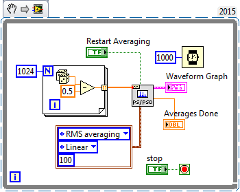
I would like to know what that "restart average" made for the FFT functions. According to aid,"reboot on average indicates if the VI restarts the process chosen medium." If restart on average is set to TRUE, the restart of the VI the selected with an average of process. If reboot on average is set to FALSE, the VI does not restart the process chosen sprawl. The default value is FALSE. When you call this VI for the first time, the averaging process restarts automatically. A typical case when you need to reboot on average is when a major change of entry occurs in the middle of the averaging process"
I realized that the FFT function takes in an array of values and perform the FFT on it. If the FFT function keep a buffer previous values and clears when restart average = true? Because the FFT functions are not Point by point and they take both in all the data to deal with, "a major change of entry occurs in the middle of the averaging process" can be true?
Thank you!
Sigh. I really tried to explain what was going on (probably) with this function, you use (and, I thought naively, you understand), but you got me wrong.
This VI creates a zero average noise signal, providing 1024 points per second. Do you know what should be the power spectrum of the signal? Due to the randomness of the input signal, the power (for a small finished sample) spectrum will also have a random component. If you had several ghosts of power on average, the average would begin to converge with the expected for random noise power spectrum.
If you run this VI and look at the Spectra resulting (on average), you will notice that the first spectrum is the most "spice" and that spectra are averaged, the variation is reduced and diminishes the value of crete (shown by looking at the scale of Amplitude). At any time, you can press "Reset average" and see this... reset the average, the following spectrum shows the growing nose, etc.
It shows the right way to test the function of the power spectrum and discover what he does. My suggestion as to what makes this function seems to be largely correct.
Bob Schor
-
How to create a table of 0 and 1 as a filter after a FFT
Hello!
First of all, sorry if my English is not very large, I'm native French... And I am a beginner with Labview.
I would like to filter some of my noise using a FFT, multiplication by an array of 0 and 1 that I chose myself, and then make a FFT - 1.
I know there are filtration solution implemented in labview straight forward, but I really wish to go my way.
My question is: I'm a bit lost in the possibilities of painting. How can I design one that will have the line number I decide (I have a link with my sample) and a succession of 0 or 1, without having to type 0 and 1 two hundred times?
As a result, I just want you multiply the result of my FFt by this new table.
Thank you very much for your attention!
all those are adjacent?
If so, initialize a matrix of zeros with the length, the initialize a smaller array with all zeros and use 'replace the subset of table' to place in the largest table in the right place.
-
Hi, I can't manage with table 2d FFT. I convert the data from excel. In labview, it is a 2 columns with array of 10000 lines. Then I traced chart XY in this table (using "build the graph XY") and it is well marked. Now I need to use FFT on this and I really can't understand it. When I use the spectral measures it shows something like one noise, or other random * beep *. How my VI looks like is attached below. Sorry for my English
I added a power spectrum in your VI. The result looks like what you would expect.
See you soon
Edgar
-
Makes great table location of memory permanently
For the transfer of data from 100 M/s, I tried to create a table of 100 M and will pass the pointer of the array to a C program. The C program get the needle table and write to it.
Just wonder if big Board has permanent memory location. If OS or labview doesnot assign continuous memory to this great picture. There will be an error when the C program tries to write to the table.
Any suggestion, thank you.
Arrays always have in contiguous memory. It is a fact, for each programming language, I know, is true for C as well as regards to LabVIEW.
They got ways to 'emulate' contiguous memory in order to nihilate certain constraints of the system, but those who are most often specific IDE and cannot be shared between different programming languages (or more often with an overload immens). An example of such an approach can be found here (the link works for everyone hope!).
hope this helps,
Norbert


Maybe you are looking for
-
I bought a terabyte of storage a month and now I have only 5 GB, because I did not renew the terabyte of storage. Is the amount of staorage I haven't used postponed to the next month?
-
Why doe iPhoto want to load all the pictures my camera took ever when I want just to upload 3 photos? I have just three pictures I want to load my usb for my macbook camera style
-
What about KB971033: this update will be included in Windows 7 Service Pack 1.
Seeing that it is an optional update, this will be included in Service Pack 1? I've searched and can't seem to find an answer. Thanks in advance for anything that helps.
-
After reistalling windows on a drive that dell sent me, I can't go online
First, it started with a memory error message. When I changed the ram, I went to the maximum which is 2 GB. I have the rigid cable and wifi in the pc. When I try to click on fix it, nothing happens. Dell or microsoft won't help. The pc has 2 years. I
-
When on the internet, getting error AVGWDSVC.
I get this message to the top when on the internet. This sats AVGWDSVC error message please send to Microsoft error report what is this error and how can I stop it popping up all the time Whiteley Pat