PIC FFT Analysis
Hi all
In my application, I'm analyzing a beep.
I used the spectral measurements vi for the FFT peaks.
Now I want to know the number of instances in which amplitues is over a certain limit, say 0.01.
Since I'm not an expert, I could really use some help.
I enclose my vi with a sample sound file.
Thank you
The result of the power spectrum is an array of clusters. Each cluster has three elements: f0, df and a variety of sizes. Ungroup all elements, use the table with a ridge detector function. Multiply the 'locations' with df and then add f0. The resulting table contains all vertices with the configured threshold already set on the frequencies to migrate.
Norbert
Tags: NI Software
Similar Questions
-
Amplitude of the Signal after the FFT analysis
I'm currently trying to find the amplitude of a signal after running a FFT analysis. I use this for image analysis MTF. I take the profile of the line of fire (with an alternation of black and white bars) and convert it to a signal. This signal is then introduced to a FFT Mag/Phase VI extent and output of the FFT. My program then enter the amplitude to frequency of alternating black and white bars.
My problem is that the amplitude seems to be scaling by a factor. I would like to find the exact amplitude of the signal of my analysis. Anyone know the factor of scale or any problem with my program? I joined the program and the image that must be analyzed. Just browse to the image in the VI and run the program and you will see the MTF chart resulting.
Thank you
Ronak
-
FFT and differ from the values overall btwn VI and tiara
Hi all
I have an application that displays live readings of vibrations which the spectrum and the overall vibration level. Everything my generation of report is made in the DIAdem scripts, so it is essential that all values calculated and displayed on the side of LabVIEW are the values calculated and reported in DIAdem. The VI and Script, when the entrance to the PDM attachment, attached give me values significantly different to the size of the FFT and the overall value of RMS. Can anyone spot what I'm doing wrong?
Thank you
Scott
Hello
This is an excellent response of R & D. I felt that it would be better to put it on the web, then keep it limited to your service request.
The difference has to do with the window of correction. The results are the same if you choose rectangluar (or not) window.
Usually a window takes a share of the singnal away, so in the first place, the result has a different shape and is smaller compared to train with rectangular window. This can be fixed with a specific factor for each window.
There are two possible corrections. Random and periodic.
-Periodic is used if you have pure sinusoidal signals and you want to measure the peak value. A typical use case is the window of flattop is designed for this type of calculations. The periodic correction is too great if you want to add values to calculate the total RMS signal or the sum of a certain frequency band.
-Random is correct the signal back to the correct overall RMS value and must be used in all other cases.
The periodic correction for Hanning window is a factor of two. The correction is randomly about 1.633. Tiara will give the same result as LabVIEW if you use the following type of correction:
FFTWndCorrectTyp = "periodic".
In the world of the FFT analysis, the different corrections are very often not obvious and hidden to the user. Unfortunately, it is also the case in LabVIEW. You can find a good example of explanation here:
http://blog.Prosig.com/2009/09/01/amplitude-and-energy-correction-a-brief-summary/There are different factors for different window functions. If you go further in the FFT - VI you will find "window scaling VI. It has a «constant window» output With this, it is possible to obtain the correction values for window functions.
I think also, periodical is false in most cases, when Hanning is used, because Hanning is the best for the sum of the values of the RMS in the frequency bands and the results are bad without a correction at random.
Hope that helps.
-
Hi all
I used a signal for a FFT analysis using DIAdem. I have used the following options available in DIAdem:
FFT (hourly)
Windows type: Rectangle
The FFT functions: Amplitude
Amplitude type: power spectrum
Third / Octave = No
Average of the amplitudes: none on average.
I have attached the raw data in an Excel file. In addition, I have attached an image indicating the amplitude versus time plotted in tiara on top. On the left side the data plotted using another software, while on the right side, the data is plotted to TIARA. The frequency on the x-axis is ok, but the amplitude on the y axis is not the same. I would like to ask if there is a way I can get the raw signal of amplitude with tiara, I think it's the normalization?
Thank you
Pepis21
Hello boutique,
Looking at your signal, the amplitude you want to achieve is not possible (unless you change units or you it multiply).
Imagine, if you had a perfect sine wave of amplitude of 1 you should have an amplitude of 1 when you perform the FFT.
Your maximum amplitude signal, you could get would be less than 100 (far 3.5E7)
Best regards
Andrés
-
Hello
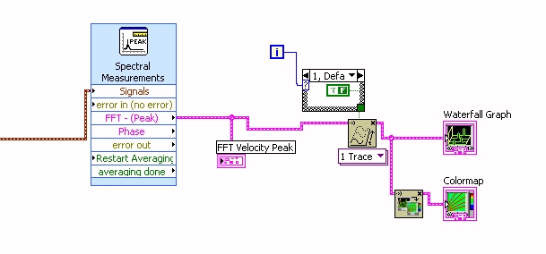
Currently I have a vibration of a map of 9234 signal and show in on different graphs having the FFT analysis on it.
The photo below shows me what doing. Unfortunately, I would really like to show on a 3-d of the waterfall chart, but have no idea how convert it to feed, x, y and z, entered for this, I'd appreciate it really if someone could shed some light on this for me?
Thank you very much
Mike
I solved this now, thanks anyway
Mike
-
The size of the FFT unexpectedly affecting maximum frequency
I was playing around with the Labview Signal Processing course manual exercises (NOR, 1997), when I came across the unexpected result. I have included below the block diagram for exercise 3.1 (one side FFT) of the manual. This demo vi had left the size of the FFT (by default). I don't know what is this default value. It is not stated in the context-sensitive help. I tried to add to the size of the FFT. Unfortunately the FFT analysis did not give a precise answer, when I put in the size of the FFT. For example, I set the frequency of the 100 s, Fs 300 Hz sinewave and non of the sine wave 500 samples. When the FFT size has been set to 256, I get 2 to 51 and 102 Hz frequency peaks. The size of the FFT of 512, I get a peak at 102 Hz. 1024 of the FFT size, I get a polymorphic waveform!
However when I put the size of the FFT-1 so I got the correct peak at 100 Hz. I guess that's the default size FFT. I could also get the correct TFF frequency, if I set the size of the FFT (500) to the same value with # no samples (500).
Is there anyway I could set the FFT size and still get the correct output of the FFT. Thank you.
This was recorded for 2011.
-
The FPGA using mathematics and analysis of VI
When I'm programming on our FPGA (in one OR cRIO-9004) my code will not compile when I use the VI in the calculation tab and analyze FPGA. The code will stop compilation and just say idle in the status area.
I can't undewrstand it.
If someone could help me it would be great. I'm looking to perform FFT analysis on sgnals.
I discovered that it was because I was not logged as an administrator on the computer. Therefore, necessatry files could not be written.
Problem solved now so just a heads - if you see something similar
-
Speed of scanning and samples for FFT affecting dt
Hello
I have currently acquire the accelerometer data and the value of the scanning speed of the clock to 5120 s/s. I use then the analog 1 d Wfm Nchan N Samp to acquire 5120 samples, then use analysis FFT on it to create a chart of the frequency. It gives me a dt 1 that is a resolution of 1 Hz.
The question I have is how can I sample the data with a dt 1 at a faster pace.
For example, I change the speed of scanning on 10240 and always acquire the 5120 samples, allows me to taste two times a second, it gives me a 2 dt (2 hz resolution) when I do my FFT analysis. All that happens to raise the rate of scanning for the sample clock is that I can now detect the peaks at higher frequencies.
By that I mean if I just scan 5120 s/s with my card, when I TFF, it goes up to 1100Hz about, if I double the speed of scanning, then this double to about 2200Hz, she then reduces the resolution
How can I improve the speed of update and still keep a 1 DT?
Thank you
Mike
-
DASYLab how to write data to a file every 15 minutes
Hi all
I use dasylab and datashuttle/3000 to record data. What I want to do is to write data to a file every 15 minutes. I use the milti-file, which can write data to the file diffenret, but how do I control the timing, as the journal data every 15 minutes automatically.
The other problem is that I use FFT analysis of the frequency spectrum. How can I determine the value of frequency where the peaks that happens.
Thank you
Write less data in the file that you have collected requires the reduction of certain data.
There are three techniques to consider.
With an average or an average of block - both reduce the data by using a function of averaging, defined in the module. To accomplish the reduction of data, choose block or RHM mode in the dialog box properties, and then enter the number of samples/data values that you want to reach on average.
Average - when you reduce the data, you also should reblock data using the block length of the change in the output parameter. For example if you enjoy at 100 samples/second with a block size of 64, the average module configured on average, more than 10 samples will take 10 times longer to fill a block. The initial block represent 0.64 seconds, the output block represent 6.4 seconds at a sampling rate of 10 samples/second. If you change the size of output in one block, the program remains sensitive.
Average block - average values in a block against each subsequent block, where the average is based position. The first samples are averaged, all second samples are average... etc. The output is a block of data, where each position has been averaged over the previous blocks. This is how you will be an average data FFT or histogram, for example, because the x-axis has been transformed in Hz or bins.
Second technique - separate module. This allows to reduce the data and the effective sampling rate jumping blocks or samples. For example, to reduce the data in 1000 samples / second to 100 samples per second, configure the module to keep a sample, jumping 9, keep one, jumping 9, etc. If you configure to skip blocks, you will not reduce the sampling frequency, but will reduce the overall amount of data in a single block 9, for example. It is appropriate for the FFT data or histogram, for example, to have the context of the correct data.
Finally, you can use a relay and a synchronization module module to control. For example, to reduce a sample data every 15 seconds, configure a generator module of TTL pulses for a cycle of 15 seconds of time. Connect it to a Combi trigger module and configure it to trigger on rising and stop the outbreak directly, with a trigger value after 1. The trigger output connects to the X of the relay command input.
In addition to these techniques, you can change the third technique to allow a variable duration using a combination of other modules.
Many of these techniques are covered in the help-tutorial-Quickstart, as the data reduction is one of the most frequently asked questions.
In regards to the FFT... use the module of statistical values in order to obtain the Maximum and the Max Position. The Position of Max will be the value of the frequency associated with the Maximum value. The output of the statistics module is a single sample per block. Look at the different FFT sample installed in the worksheet calculation/examples folder.
-
To find the first Summit for data channel
Hey guys,.
I need a little help. I wrote a script to process some data. Basically, what the script does is calculate the linear accelerations peak, peak of the angular speeds, HIC values and IF. But there is a problem with my script that I need help. In my script, I use the ChnPeakFind command to find the pics in my chains. This command works fine to find the peak value, but what I want to do is find the FIRST Summit in the data, without worrying whether or not it is a maximum. I always encountered data that varies in which my first pic (impact analysis) may or may not be the highest point in the channel. As you can see in the Graphs.png that I have attached, the ChnPeakFind command found the 2nd Summit (red circle #2) in my chain of angular velocity (ARS resulting). But what I report is the first peak value (red circle #1). I've also attached a screenshot of the section in my code where I calculate the angular velocity. The 'i' in the calculation is just the channel group number. In this case, it is 1. Anyone know how to change the code or have another suggestion how to find the first Summit in a channel without having to stop and go to the tab analysis to manually find the pic?
Thank you!
Hello
If it please see my littl below escript and let me know if this could work for you
Dim     oChnResultant

Call Data.Root.Clear)

Call DataFileLoad ("E:\Customer_Examples\01_Head_Impact\Head Impact Data.tdm", "CT", "Load")

Set oChnResultant = data. Root.ActiveChannelGroup.Channels.Add ("Result", DataTypeChnFloat64)

Call ChnXYZAbsValue ("[1] / ARS X","[1] / ARS Y","[1] / ARS Z", oChnResultant)

"Use the filter twice to get rid of the jig

Call ChnSavitzkyGolayFilter (oChnResultant, oChnResultant, 1, 12)

Call ChnSavitzkyGolayFilter (oChnResultant, oChnResultant, 1, 12)

' Delete few maxima to the beginninf of the signal.

Calculate the call ("R = IIF (R)<>

'Research for first peak.

Call ChnPeakFind ("[1] / Time axis","[1]/Resultant","/PeakX","/PeakY",1,"Max.Peaks","Time")
-
Measuring frequency VirtualBench with LabView
Hey guys,.
I recently acquired a VirtualBench for testing through LabView. The test installation I want to do is very basic. Use a DC power supply to power a crystal as a device and the oscilloscope to measure the frequency of the device.
By using the software application OR virtual bench, I had the installation works perfectly in less than 5 minutes.
However, when I move the setting in Labview I don't know the correct VI so that I can output the frequency measured as an indicator of the façade.
I installed the drivers for the virtual bench and can set the output to DC and retrieve a graph of the frequency, but like I said, I can't find a single VI included in the package that will give me the frequency as a measure as the application software OR virtual bench.
I'm missing this VI right in front of me, or the VI for measuring frequency has not been created yet?
I enclose two photographs. One is the application virtual bench doing exactly what I want. The second photo is of the VI more close than I thought to take care of my needs (read the OSM aka paid), but as you can see the only way out is an analog output, no measure included frequency.
Thanks for any help!
Best,
AndyThere is a dial tone measures Express VI. Or you can extract a single signal.
There are also many FFT analysis or spectrum of VI.
-
Why is my pic jpeg analysis always at 300 dpi. ? I select 150 dpi on the Panel of the scanner, but it always ends up 300 on
the computer?
Hello.
When you scan directly from the printer operator panel, the settings and options of PPP would be controlled by our MP Navigator program on your computer.
Please open the MP Navigator program on your computer. Then, open the Preferences menu to access the settings of scanning of the Panel.
If additional information is required, please call us at 1-800-OKCANON.
-
FFT 1 d 2D spectral data with GPU Analysis Toolkit
Hello world
I'm trying to implement a parallel my data 2D fourier transformation using the GPU analysis tool. Given that I've never used this tool, I tried first to implement a simple transformed of Fourier of a simple real signal to an output complex vector. For this, I found an example on the internet and adapted a bit. Unfortunately, I don't get any output, but I don't have an idea why. I have attached the VI then perhaps someone could take a look? I would appreciate if some could help me with this problem.
Thanks to anyone who can help me
Simon
A brief information. I was able to understand the problem. The problem was caused by a Version of the box again CUDA Toolkit. I installed the 4.1 Version and now everything works fine.
Simon
-
Using FFT to palette spectrum Subvi Interface of FPGA functions
Hello
I use the card PCI-5640R and PXI-5600. I want to use the "scale" and "FFT" exspress screws to the range of functions 'Mathematical FPGA and analysis' in my VI "FPGA VI" and "FFT spectrum for '"FPGA interface"in my"host VI.
A poster of the code examples in which these three subVIs are used can.
Thanks in advance.
Kind regards
Rashid
Hi rachid,.
There are two examples of delivery here: LabVIEW 2009\examples\R Series\FPGA Fundamentals\Analysis and Control\FFT\
Jim
-
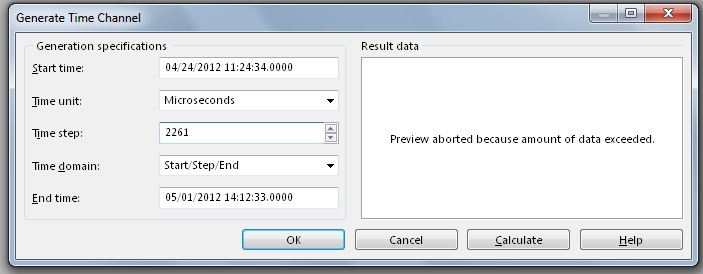
Hi, I work analyze signals of vibration thanks to tiara, data are from 4 to 5 million points in three or four hours, the problem is when I run the analysis FFT only shows me frequencys up to 300 Hz when I know that I measured frequencys of 3 500 Hz.
The measurement parameters:
Frequency: Hz 12800
Number of samples: 1200
Tiara parameters:
Values: 4 757 810
Time: 11:24-14:12
To match my data with time in tiara, I divide the number of values between the seconds of the archipelago.
It was my setting, I Don t know if they are correct and I can´t figure out why it shows me frequencys up to 300 Hz.
Thanks and regards.
Hello Rolando-stc,
I've done some tests and I actually reproduced your problem to get frequency much lower than expected with the FFT. The problem is the way you build your weather channel data. ¿WHERE do you get your data points? The thing is that sometimes the data comes in the form of waveform data. This means that these data already include a channel in time in the same channel, so you don't need to generate a time warp to compute the FFT. If your data is a digital channel only, you need not generate a time warp to compute the FFT. How to calculate the time channel is given the sampling frequency of your data. For example, I have a channel with 325000 points, and the sampling rate was 50000Hz. This means that I have to generate a time with a stage of 20 channel (1/50000) in order to obtain a measure of the FFT of 25000 Hz. If I use a stage of 20 with a selection of field time/Step/bib and 325000 as number of values in the window generating weather channel, I get the channel early to use with my data to compute the FFT. In your case, your sampling rate is 12800Hz, which means that no time should be 78.125us in order to obtain a measure of the FFT of 6400 Hz. In your post, I noticed that you have a different time step. On the other hand, you say that you get a total of 4757810 data points. I do not understand how you get this tip with the sampling rate interval and the time you mentioned. I suggest you create a weather channel using the stage early and check that the data points total is correct. You can use a string of hour or a digital channel, it doesn't really do much since you get the same result for the FFT. I hope this information is useful. Don't forget to post back if you have any questions.
See you soon
Maybe you are looking for
-
Text of Firefox tabs, settings, firefox, menu button... does not load, if I'm not in safe mode.
Issue describes the situation well, for some reason the text beside all my buttons (including everything in the area of the firefox button) has disappeared. Web sites work well, it just seems to effect the entire text of the firefox program. I delete
-
Yahoo toolbar is all that appears, how to recover default settings.
We lost the top tool bar with the "back" button, stop, refresh, logo address and URL of the home screen. How to reset us bars menu to its original settings?
-
security update is not available
my microsoft xp program is protected by a security update msn program. MSN wants to upgrade the program (warns me that the upgrade is available,) but is rejected (does not load) when I try to accept it. I have to do something that prevents me from a
-
Hey there I have a Mini Mac OsX 10.4.11, but cannot get a driver for my new HP 7500 has. I really need to be able to print off this computer. Is there anything that can be done to remedy this? Thanks a mill Liz
-
Hello Anyone know the regex string to Boolean operator "AND". I got to know OR operator has string ' |. ' But impossible to find the string for the AND operator. any help would be appreciated.