customize multiple scales of Y in a wave chart
Hello
I'm showing two channels in the same form of wave, but with scales graph Y distinct. And I want to customize the two scales Y independently using nodes property. But I found under the node property of waveform graphic, there is only a single scale of Y.
Does anyone have the experience to customize them independently using nodes of property?
Thank you
XP\LabVIEW 2011
Use the "Active Y scale" property to select the scale you want to act accordingly.
Scale Y Active value of 0 (the first scale of Y), then set all the properties that you want for that 1 scalethen Y Y Active set at the scale of 1 (the second level Y) and again to set all the properties that you want for this 2nd scale Y.
Hope this helps
Tags: NI Software
Similar Questions
-
Multiple scales, sides of swap (LV8.5) problem
A problem I know must be easily soluble and indeed I have graphics with several scales in a number of my applications with additional scale traded on the other side. Today, in the execution of the following command to create a second X - or y-axis of, 'swap sides' is always grayed out in the menu contextual right click. I clicked everywhere near the ladder. With the help of LabVIEW 8.5. Any help is appreciated.
Add X - and Y-scales multiple graphs or diagrams Dim hasPlayer, hasPlayer playerversion = false playerversion = 10 Do While playerversion > 0 On Error Resume Next hasPlayer = (IsObject (CreateObject ("ShockwaveFlash.ShockwaveFlash." & playerversion))) if hasPlayer = true then Exit Do playerversion = playerversion - 1 loop is_FlashVersion = is_Flash playerversion = hasPlayer
Perform the following steps to add a scale to a waveform graph.
- Right click on the shape of wave or chart chart scale and select duplicate scaling in the context menu.
- To move the ladder across the screen, right-click the new scale and select Sides Swap in the context menu.
-
Chart with multiple scales of Y
Hello
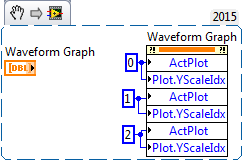
As you can see in the excerpt, I'm trying to plot a graph with several scales of Y. What do you think is wrong with it to get the following error.
Possible reasons:
LabVIEW:  invalid property value.
I wouldn't change nothing to indexing. You already wrote this code.
I clicked the balance you already had and clicked on "Double ladder" to create the second and third. Once they have existed, the crux of your property has worked fine as it was.
-
The wave chart shrinks back each time when you arrive 5 minutes
I made a graphic waveform that have 5 major minutes thick, but I noticed that whenever the table lines reached 5 minutes, it will shrink to 3 minutes and repeated the cycle.
I have changed the balance here and there but could not make it work. the time scale is follow time system or it kept shrinking back.
A I misunderstood something?
Hey,.
Increase the length of Bediet of the chart (context menu).
Christian
-
Why the wav chart disappear but still play?
I am a user of Cool Edit for a long time and have a first problem of time, something I've never seen before. I'm in the middle of cleaning the pop and click on from an old vinyl record. I'm working on this issue throughout the week. Last night I recorded the current file and when I opened this morning the graphic display for the first minute has disappeared from my screen. Yet, when I click on the game from the start, he played my record and it seems to be the fully edited saved version. I tried to zoom in all the way to the 'points' and still don't see anything on the screen. When I zoom on the last part of the song which is visible, everything is normal. The file is read as completely when you use other programs as well.
Any ideas on why my song "disappeared" but is not yet?
Alan Hilbert
Looks like a corrupted file .pk to me - which is easy to fix. Go to the directory where your wav file is stored, locate the .pk file associated with it (it will have a homonymous denomination) and delete it. When subsequently, you re - open your wav file, .pk files will be recreated.
No, I don't know why or how it has been corrupted, but if it is that view that it affects, there is really no other choice in terms of setting.
-
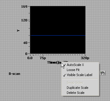
time scale is not shown on my chart
Hello
This may seem a very stupid question, but I was stuck on this for the last 2 hours and I could not find an answer anywhere else on the forum, so here goes. The timestamp (dt) on my graph will not appear. It shows the whole numbers of samples and does not care what is my sampling rate (dt). I read somewhere that it could be because "the timestamp is ignored", this option is grayed out, so is not applicable here.
I added a picture of the code where the waveform is created (if it is trivial). Any thoughts?
Hello
I just noticed that the point of constraint comes from my stream. Attaching a normal array it makes the point of disappearing, and then the chart ignores my dt. So the problem must be with my bitstream.
EDIT: For some reason, wiring of the table that is normal to the curve, remove and then rewiring my flow for the chart has solved my problem... I have no idea what happened, but now the sampling frequency is taken into account. (the point of constraint moved to my block of convolution, now, which indicates a problem with my the filter coefficients, but it doesn't seem to work now).
-
Add the second scale of Y on the right side of a chart
Hello
I use a waveform table to display temperatures (scale Y) versus time (X-Scale).
My card is wide enough to see a range of "long", and I would just copy the scale Y
and display it on the right side of the chart once again, simply for better readability of the temperatures.
I tried with the option of customization, but I am not able to copy and paste the scale Y.
Thank you
Patrick
When using multiple scales, you need to set the "ActiveScale' before applying the changes. You can avoid race conditions if you expand the node for your property to include the active scale as the first property.
Ben
-
Wavelet transform scalogram frequency scale
I've read all the posts on this topic and found no answers, that would be useful for me. However, I found a formula to convert pseudo frequency scale. My client wants scalogram with the y-axis as the frequency of the signal and x-axis as of the time of the signal. I tried to use the multiplier of the graphical indicator property but I can't get the correct values of the frequency in the Y axis. The formula I use is f = Fw / (dt * s) where f is the frequency of nickname, Fw is a center frequency of the used Wavelet (Morlet), dt is sampling the signal time and scale. FW is 0,8125 Hz (at least that is what Matlab tells me), dt is 0.01 s (100 Hz aqusition), the scales are numbers from 1 to 128. Basically I wan't to know how to convert the graphical indicator scale. I drew the correct chart in Matlab, but I must do the same in Labview. I have attached two screenshots.
Hello
Well, you can use the property nodes in order to change the scale.
If you right-click Scalogram, create, property node and you choose the multiplier and offset.
You simply calculate the offset, it is about 80,61 and the multiplier is on-0,63. And you calculate scale of nickname.
The use of knots of property you can change a large number of parameters for the scalogram.
Hope that solves your problem.
Kind regards
Ion R.
P.S. As LabVIEW is an engineering environment, it is not so obvious how you can reverse time :-) (or frequency)
-
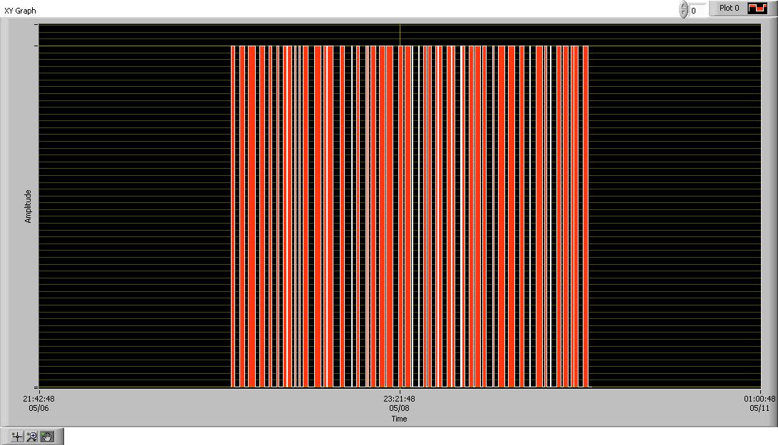
That's what I'm trying to do. I have a file periodic_chan3.bin which is sampled values of three channels of periodic signals in interlaced format. The data is stored in binary format (long of floating point of the double procession) DBL and big-endian representation. I am reading the file and draw all the three waveforms on the graph of a waveform. The data has been saved from time zero, with a sampling frequency of 100 samples per second. Then I scale the x-axis of your waveform graph so it displays the time in seconds.
So I try, on the wave of the chart to create three sets of cursors and cursors to display the average value of each of the three waveforms. The color of the cursor Y for a given signal average must match the color of the display of the waveform on the chart. For example if the graph of the signal is displayed in red the cursor there shows the average of this signal must be red.
What happens when I do not open the file I see a white contour mesh a sine graph, a graphical square and sawtooth chart. I can't seem to trace the three waveforms seen clearly with the three above-mentioned distinct colors. I can't seem to sort correctly and represented as mentioned above.
I would also help with the calculation of the average or expected from each of the three periodic waveforms.
Attached are the files please help. Pgm4 is the VI, and periodic_chan3 contains the data that needs to be sorted. I'd be very happy if somene were able to fix the and submit the changes so I can see how it works. Thank you.
Edit: I get an error that says periodic_chan4.bin "is not a valid extension of an attachment" so I'm not able to uplad it. Is there a way to othe I could download it?
Xtasy26,
In your post you mention that you try to view 3 averages of waveform, however your code is showing that you are broadcast 4 values. This might be the reason why your getting the different forms of data. Instead of an array of all the waveforms 1, then a table of all 2 waveforms and a waveform table 3, you get a mix of all three in each of your waveforms.
To calculate a moving average or mean that it is actually an integrated in the example in BT sound finder called "running Avereage.vi calculation"
You can also view the attachment to see Multiple waveforms channel displayed on a single chart.
-
"Graph - Simple" change issues to include several axes
I'm changing the workspace "Graph - Simple" object to allow several axes. However, I was do unexpected behavior and I can't find a way to restore the configuration when the next load.
- Is there a way I can use the "Custom Data" variant in the Item.Data cluster to store the configuration?
- If not, is there another way I can do this work within VeriStand without having to re - develop a full graphical object (based on the free label template) just to add this feature?
I am currently using VeriStand 2014, but I can be updated until 2015, if there is a new feature that would help.
Thank you!
You're very close to having the right answer, but what you call won't work, unfortunately. Overall, it would be nice to put data in the custom as attributes of variant data field, as long as you crush all VeriStand attributes can be expected otherwise. Even if you do this, however, there is no way to save this copy of the cluster of the top-level VI item data. I can't in any way you can get this to work.
However, you do have to start from scratch. It is an available add-on here called Multi-Y chart with channels calculated. It has multiple scales are natively, but this is a graph open source with a superset of the features in the chart - simple. Here you could probably change to have two or more axes and find a good way of saving data so that it persists on the next load.
I did not write this control and never used personally, but it might be a more open alternative to watch before thinking to start over from scratch.
-
Which is good for the unit, weighing between NI9237 and NI9219?
Hello
My name is Jeonghwan Lee and I am a new setting of load cell measurement system.
In my lab, we must implement the load cell measurement system of multiple scale and equipment using OR.
And in the future, we want to measure the torque sensor or pressure sensor.
I consider just between the two models (NI9237 and NI9219).
These two models can measure sonsor as load cell signal, but I don't know what is best for me.
We want a module that is easy to configure and has more precision.
Load cell that we use is LCMFD series of Omega.
I know my question is ridiculous. However, I'm not a professional man in this area, so I need your help.
I have attached a spec of load cell.
Thank you
If you don't need the dynamic range (100 Hz to 50 kHz samplerate sampling rate) I would tend to the 9219, however, a point is the voltage:
Some sensors (piezoresistif) bridge must (must) be supplied with voltage defined (usually from 5V or 10V) levels and the 9219 a other supply voltages! Check with your provider of sensor!
That would be a point to the 9237.
Ask your Rep OR local if you can test both.
Migth be that only one card is better on noise figure in your application. (If you compare: higher sample rate usually means more noise, but a medium filter allow you to compare)
The specification of pure sound is not the whole story.
Accuracy of the two cards is better than the specifications of your sensor.
-
I have what I think should be a pretty simple problem to solve, but I just can not work begin.
I have an 'event' - not a LabVIEW event, but a thing that happens. I measure when it starts when it stops happening and carry forward the value of the timestamp in these moments and happening. -Easier to demo, it would be to save the timestamp of each time a Boolean changes state (I simplified my problem a bit for this).
Event occurs for an unknown duration - could be 3 more days, State chaning every 60-2 minutes.
I want to plot a graph of historical events.
(1) in real time
(2) of the log file, I did (should / could be the same code)
Basically, I want to turn a set of data points n, at different times in a square with a timestamp in the base wave chart. The data points are not evenly spaced.
How anyone would set in this respect?
See you soon
James
Hi James,
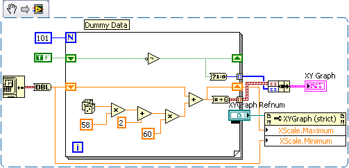
NA not want to post this as not completely happy with it but it can give you something to look at:
EU set the scale with a property node for some reason when AutoScaling, he left all the data in the middle with large gaps each end.
Do not in fact also looks bad that. The data now fill the entire graph. I don't know why but when I copied in 'Paint' she returned to data with gaps in the middle of each side.
It will be useful.
RGS,
Lucither
-
y-axis of the graph scaling using msum
Jin
Is it possible to change the y-axis(sales-msum) Beach in the charts? I search, but could not find the right answer for this.
Let's say I have my sales range y-axis 0-1 million, but have not all values under 0.8million. If I want to keep my range of chart axis starts from 0.8million. I have sales in the grid that is calculated using msum.
Y at - it such an option to customize the scale of the y-axis?
Thank you
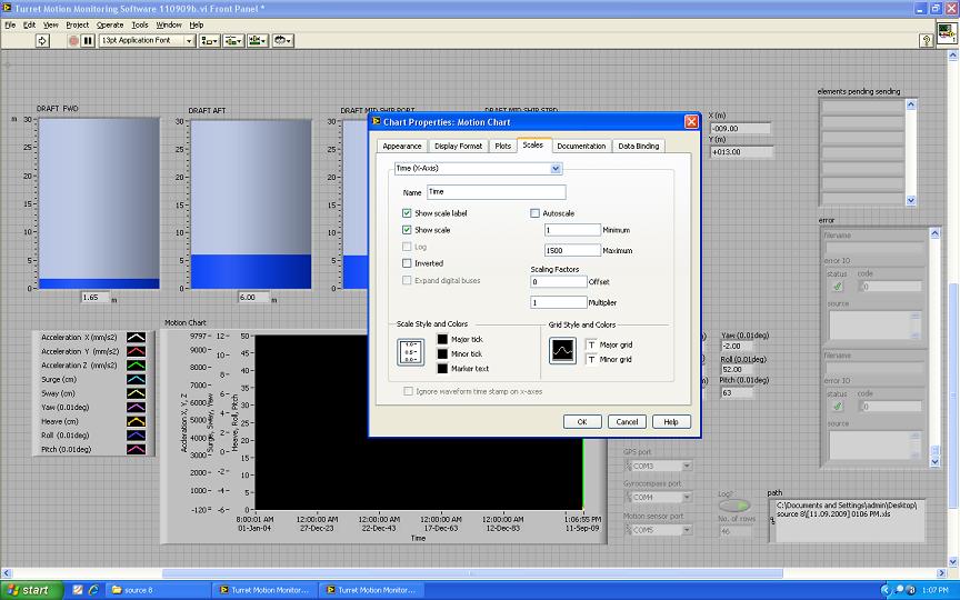
ManiHi Mathieu,
You can do this by setting minimum and maximum value in the axis scaling (averages tab in 5 tabs for chart) in the chart view.
Thank you
Sandeep -
Invalid value for the cursor.xscale property
I am creating a property node for "cursor.xscale", but when I try to write a numeric entry in it, it does not accept any value (at least all the values that I tried). An error indicating that the value is not valid. What is a valid value for this property and what exactly makes this this property (not a lot of documentation available I guess)
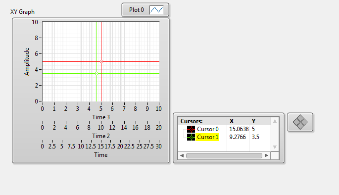
the XScale property is a number from 0 to n - 1, where n is the number of scales X you have on your chart (usually 1).
Here is an example of chart scales of X 3 and 2 cursor associated with the scale 'Time' and 'Time 2 "respectively.
The reason why it is important, it is that the X values read you in the column 'X' cursor will be different depending on whether the cursor is associated with one or the other ladder, as you can see above.
HTH.
-
Hello
Here is the link to the help of LabVIEW:
http://zone.NI.com/reference/en-XX/help/371361J-01/lvhowto/addingmultiplexandyscales/
This explains how to add the auxiliary axis on a chart.
Couldn't see any Double scale option on my 2015 I of LabVIEW.
Any comments welcome.
Thank you
Click right on the scale of the waveform graph or chart
Maybe you are looking for
-
Scanning profiles will not be displayed - Mac OSX 10.5.8 - Photosmart Premium C309g-m [2D516B]
Hello world I was wondering if someone could get an idea about this problem. I can't use my driver 'HP StudioScan' because the 'profiles' will not load. It goes like this: I opened StudioScan HP. A window opens that says: "none of the profiles cust
-
600EX Flash - 5 d III. The flash exposure compensation.
How can I set the exposure compensation to the FLASH of the camera. It seems that I have to set on the back of the flash exposure compensation. I wish I could change the settings of the FLASH of the camera, not the flash.
-
I get the xpmcom_core.dll message and things don't work... help!
Some aspects of programs to load is no longer in its entirety... for example: colors are missing, etc. I'm not much more for computer - speak so I need simplified English help! Thank you...
-
The upgrade card NIC to onboard LAN, Windows 7
Hello everyone. Have a basic question for the upgrade of the Ethernet card or the card NETWORK on my Compaq Presario under W7 Home Premium. Initially, this machine ran Vista. I installed a PCI 3Com NIC {3Com EtherLink 10/100 PCI TX NIC (3C905B-TX)}.
-
The drive - to enable or disable write protection
The drive - to enable or disable write protection?