y-axis of the graph scaling using msum
JinIs it possible to change the y-axis(sales-msum) Beach in the charts? I search, but could not find the right answer for this.
Let's say I have my sales range y-axis 0-1 million, but have not all values under 0.8million. If I want to keep my range of chart axis starts from 0.8million. I have sales in the grid that is calculated using msum.
Y at - it such an option to customize the scale of the y-axis?
Thank you
Mani
Hi Mathieu,
You can do this by setting minimum and maximum value in the axis scaling (averages tab in 5 tabs for chart) in the chart view.
Thank you
Sandeep
Tags: Business Intelligence
Similar Questions
-
DateTime on x-axis of the graph of the intensity
How can the x-axis of a graph of intensity be configured to the DateTime data type, similar to the graphic waveform XAxis? You can set the FormatString DateTime MajorDivisions, but has no way of installing the x-axis values. Waveform curve has a foot (double [], DateTime, TimeSpan) function that will implement the XScale with the correct DateTime values, but the graphic intensity doesn't seem to have a similar capability. I tried to configure the graphic intensity YAxis MajorDivisions DateTime Format string and pass then the plot function Tick values for the yScaleStart and YScaleIncrement, but it does not work probperly. MS2012 release notes say that the curve of intensity has now an automatic formatting for displaying DateTime on axes X and Y. I tried to use this feature to test the DateTime X and the ability to axis Y; However, the function of automatic formatting is not available for the chart of the intensity. Any help is appreciated.
Thank you!
Jon
Hello
Try the following code piece.
            // Set the label format correctly            intensityYAxis1.MajorDivisions.LabelFormat = new NationalInstruments.UI.FormatString(NationalInstruments.UI.FormatStringMode.DateTime, "g");
            intensityYAxis1.Mode = NationalInstruments.UI.IntensityAxisMode.AutoScaleExact;

            double[,] data = new double[100, 100];

            for (int i = 0; i < 100; i++ )
            {
                for (int j = 0; j < 100; j++ )
                {
                    data[i, j] = (i + j) / (colorScale1.Range.Interval * 2);
                }
            }
            // IntensityGraph only understands double values. But graph can interchange the data value from different types using the DataConverter provided by NI.
            intensityPlot1.Plot(data,
                0,
                1,
                (double)DataConverter.Convert(DateTime.Now, typeof(double)),
                (double)DataConverter.Convert(TimeSpan.FromDays(1), typeof(double)));
It will be useful.
Habim stone
National Instruments
-
Add image icon on the horizontal axis of the graph
Hello
Is it possible to add an icon image to horizontal axis of a graph in addition to the label?
Guidance in this regard is greatly appreciated.
Thank you
Hi Fulgence,
You can try this code... Hoping than that, this is what you need
Import mx.collections.ArrayCollection;
[Bindable]
private var expensesAC:ArrayCollection = new ArrayCollection ([] collection
{Month: "Jan", profit: 2000, expenses: 1500, amount: 450},
{Month: benefit "Feb": 1000, expenses: 200, amount: 600},
{Month: "Mar", profit: 1500, expenses: 500, amount: 300},
{Month: "ARP", profit: 1800, expenses: 1200, amount: 900},
([{Month: "May", profit: 2400, expenses: 575, quantity: 500}]) ;
]]>
Height = "100%" width = "100%" layout = "horizontal" >
paddingLeft = "5" = "5" paddingRight
showDataTips = "true" dataProvider = "{expensesAC}" >
paddingLeft = "5" = "5" paddingRight
showDataTips = "true" dataProvider = "{expensesAC}" >
override public function set data(value:Object):void
{
If (value! = null)
{
axisLabel.text = value.text;
}
}
]]>
Thank you
Jean Claude Chari
-
Invisible - axis of the graph & quot; lose & quot; the space?
Hello
I'm trying to get rid of the axes in a chart (stacked). What makes the invisible axes and "exclude" layout was easy, but the lines still seem to occupy little space in the layout:
<? XML version = "1.0" encoding = "utf-8"? >
"" < mx:Application xmlns:mx = ' http://www.adobe.com/2006/mxml ' layout = "absolute" >
< mx:Script >
<! [CDATA]
Import mx.collections.ArrayCollection;
public var dColl:ArrayCollection = new ArrayCollection([)
{a: 'a', b:10, c:20}
]);
[]] >
< / mx:Script >
< mx:Panel x = "10" y = "10" width = "687" height = "234" layout = "absolute" title = "Too much space..." ">
< mx:HBox height = "80" left = "0" right = "0" verticalAlign = "middle" borderThickness = "1" borderStyle = "solid" >
< mx:Label text = "YYYY" / >
< mx:BarChart id = "barchart1" width = "100%" height = "100%" dataProvider = "{dColl}" >
< mx:verticalAxis >
< mx:CategoryAxis / >
< / mx:verticalAxis >
< mx:verticalAxisRenderer >
< mx:AxisRenderer includeInLayout = "false" visible = "false" / >
< / mx:verticalAxisRenderer >
< mx:horizontalAxisRenderer >
< mx:AxisRenderer includeInLayout = "false" visible = "false" / >
< / mx:horizontalAxisRenderer >
< mx:backgroundElements >
< mx:Box visible = "false" includeInLayout = "false" / >
< mx:GridLines visible = "false" includeInLayout = "false" / >
< / mx:backgroundElements >
< mx:series >
< mx:BarSet type = "bunk" >
< mx:BarSeries width = '100% ' displayName = 'Series 1' xField = 'b' / >
< mx:BarSeries width = '100% ' displayName = 'Series 2' xField = 'c' / >
< / mx:BarSet >
< / mx:series >
< / mx:BarChart >
< mx:Label text = "BBBB" / >
< / mx:HBox >
< / mx:Panel >
< / mx:Application >
I would place the figure closer to the label on the left, but some (sub-?) component of the map is a space "wasted" on the left (and below).
Anyone know how you can minimize the space occupied?
TIA
UweTry gutterTop and setting gutterLeft
-
Secondary axis on the WPF chart
Hello
I'm tracing a secondary value axis on my WPF chart. I have a graphic linked to a table of AnalogWaveform
of objects that I change during execution. This table can be different sizes depending on the user's selection, however assume that there are two types of data to the chart. I would like to match a data type of my main axis and the other guy to my axis is secondary. For example, I have four AnalogWaveform
opposes the plot, two of whom are in Hz (primary) and the other two in Volts (secondary). According to the documentation, I need an additional of
element under my definition of . What I have is:
This adds a second value axis to the left of my main axis. What I need is for this axis which will be located to the right of my chart and somehow to draw each
AnalogWaveform on the right y-axis. I build my locations in the code as follows:
_graph. Plots.Clear ();
RawData is my AnalogWaveform[], built in advance based on a response from the server
foreach (AnalogWaveformwaveform in RawData)
{
If (waveform! = null)
{
field = new plot (waveform. ChannelName);
parcel of land. DataContext = waveform;plots. Add (Plot); plots is a simple list
}
}_graph. Plots.AddRange (studs); Add locations to graph
_legend. ItemsSource = plots. Add locations to the legend
Any help would be appreciated on how to do it.
Thanks in advance.
To position your second Y axis across the graph, set the
Locationproperty on the axis ofFar.To associate a plot to a default axis, set the
VerticalScaleproperty on the ground in the axis value is appropriate. -
Using an algorithm of scaling of the graph of a waveform within a Subvi invisible?
Hello
I have a little problem with the automatic scaling of the graphs.
First of all:
For automatic scaling of the axis LabVIEW uses the set of data that was sent to the curve. If I zoomed in on the inside, the automatic scaling always uses all of the data even if it is not visible at the moment. To resolve this problem, I read on the positions of the zoom sliders and values min/max within this area of research. This method works.
Second:
Now, I want to the scale of the axis using the specified min/max values. Labview graphics using a special algorithm of scaling according to the format of the axis. I want to use it, so my idea was to send the cut data and format of the axis to a Subvi. Inside this Subvi, I use a waveformgraph to display the cut data and run an automatic scaling once. Now, I read the values min/max of the graph and set this values on the main chart, I see in my program.
The result is, my main chart shows the data zoomed area in maximum size (to the axis scale) and hole data is always available, so I can still pass the data in the chart or others.
Problem: The sense of scale with a grpah inside a Subvi only works if the chart inside the Subvi is visible. If it isn't, no scaling would be made. My solution is to open the Subvi as a small window and close automatically after the scaling. It's not very nice.
Are there any other ideas how to use auto scaling without showing the front of the Subvi?
Thank you very much and best regards,
Michael
Hi Michael,
-show your façade out of the visible screen area, so the user does not notice the window...
-Make your own algorithm of scaling based on these values min/max...
-
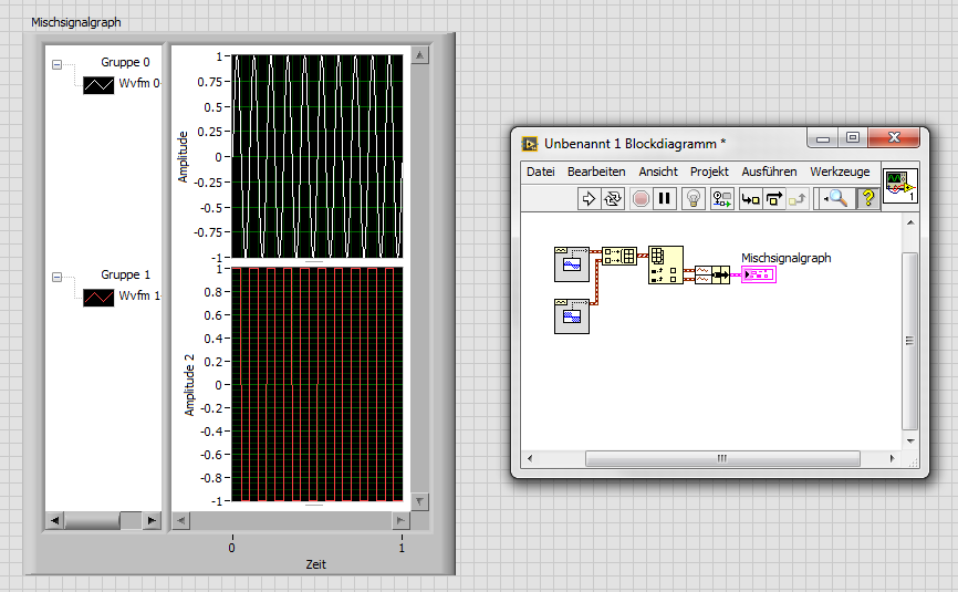
How to trace the temperature and voltage using the graph of Mixed Signal
Hello
I use the NOR cDAQ-9178, module NI 9214 (temperature) and the module NI 9201 (voltage). My program allows the user to choose among 3 different tasks, Masurement of temperature, voltage, or both. When you select the task for temperature and voltage measurement, I was drawing all channels on the same graph. I was invited to separate channels of temperature and voltage and draw on a split graph, using the same category axis. I tried stacking, but could not control where each parcel channel went. I think the Mixed Signal graph would work well. Everything works and records all the data of the channels to the files, but my plots appear not on the graph, although I can see the change in scale numbers. I think I can use the cluster incorrectly. Can someone tell me what I am doing wrong? I selected the 'Plot Visible' option, but the plot is not always displayed. I've attached a zip with all the screws needed to run my program. The main VI is "Voltage_Temperature_SingleTask_Measurements_MAIN.vi"... but everything must be downloaded to the program works. Please help... Thank you.

Hi mzhlb,
I complained only the expressVIs.
Why not use simple IndexArray function to get bots waveforms of your waveform table? (I faked it your DAQmxRead with functions SigGen).
-
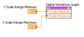
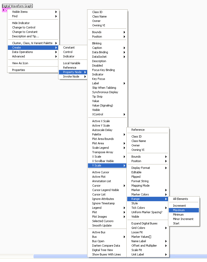
Is it possible to scroll on the y-axis of a graph of digital waveforms?
Hello!
I use LV 8.5.1 and I want to draw 64 signals on a graph of digital waveforms.
But if the graphic is too small, I see not all signals, and if I enable auscale on the Y axis, so the signals are not recognizable.
Is it possible to activate the scrollbars on the y-axis?
Thank you.
Hello!
Try to use the nodes property Y scale with a slider horizontal/digital control. As:
Find it here:
I hope this helps!
-
4.2.1
Hello
In a bar graph when we left say counts on a bar y axis, and if the numbers are like 1, 2, then the y axis shows the values as 0,0,1,1,2. There is no parameter to play with the values on the axis. It seems that automatically, what he wants, perhaps based on what ever the values it becomes. I expected something like 0, 1,2,3... etc.
Any suggestions on how to fix this?
Thank you
Ryan
Hi Ryan,
By default, the automatic calculation used for graphics mode is 'Basic', but it seems you use the parameter "Smart", as indicated in the AnyChart online documentation here: http://www.anychart.com/products/anychart/docs/users-guide/Axes-Scales.html#auto-calculation-modes. To apply this setting to your chart, go to the page graph attribute, value "use Custom XML' Yes and update the
tag to the tag y_axis to set auto_calculation_mode ="Smart ". auto_calculation_mode = "Smart" / > I hope this helps.
Kind regards
Hilary
-
How can I use axis layer against the axis of the world to animate?
Hi all
I'm open to other ways to address the issue.
I am trying to create a sphere using multiple images. Say, 200 images, arranged in 3d space, so they face outward and together form a large sphere. Pretty standard thing (like the sphere glowing apps blue droid in android ads, like this).
I used red giant PlaneSpace quickly take a sphere. I want to "explode" the sphere for all images to move away from the centre of spheres, but in a staggered and random way rather than all at once.
I thought it would be easier I see each orientation layers changed each axis of layers. So the layers of the z-axis of the Center points.
Example:

I tried to use a simple linear expression to update the Z axis over a period of 20 seconds to its current position minus 2000, like this:
AMT = linear (time, index, index + 20, position [2], [2] position - 2000);
Transform.position = [position [0], [1] position, amt];This updates the position of the z axis, but it is based on the world axis (or axis of the model), not the axis of layers. The axis of layer, I want to talk about is the widget of the axis that appears when you select a 3d layer and the axis 3 widget to see red/green/blue appears.
How can I get the expression to use the axis layers rather than the world?
Is there another approach to this? I'm certainly not up-to-date on 3d trig enough to write a formula to chart a course far from a specific 3d point. If all goes well, there is a simple way to do this that I forgot.
I will add that I have attach all 200 pictures to a null value, scaled to null, and it grows not all photos now. I also added a reverse scale expression to keep them the same size they were initially instead of scaling upwards with a null value. However, I really want to blow way random and not "both" and I need to get out of the null concept for this scaling access to each photo.
Thank you!
Unplug the layers of the null value and try this:
AMT = linear (time, index, index + 20, 0, -2000);
toWorldVec ([0,0,1]) + value * amtDan
-
How to use the graph of the intensity in the iPad data dashboard.
Hello
I use a graph of intensity in my vi main under a project of myRIO.
I created a shared variable of the 2D array. When I selected the variable in the ipad it does not show that he presents in the pc...
I want to mention that I have selected the multiplier as (= 30/255) 0.117647 in labview in pc
I use the version of labview 2015 myRIO.
and I am using iOS 10 in my iPad
can someone help me please
Hi adil,.
The graph of the intensity is not supported in the dashboard of data.
Kind regards
Denny
AE Singapore
-
Hi, I have two decimal strings, each of them contains the numbers change over time. I want to plot them on the graph XY, a string for each axis. Can you show me how do?
This is not a formula, but a constant simple schema of a table complex. Wire remains, then do a right click of the terminal of the initializer of the feedback node and select "create constant. That should do it.

-
Plot the graph of origin using Labview
Hellou,
I try to plot the graph of origin using Labview. In Labview I connect and create the new model of origin for instance. Template file (.) OPJ) was created before. End of data in the worksheet then I plot the graph of origin. But I can't use OA_NewEmptyGraph.vi because it is to create a new chart. I'm trying to graph in graph model.
In labview that I found for OA_FindWorksheet.vi sheets, it's journal to find, but a cant find, a few "OA_FindGraph.vi" is - it is or made elsewhere?
Thank you
Norbert
Hi Norbert,.
your question seems to be linked to LabVIEW, while you're wrong he posted in the forum of LabWindows/CVI.
-
Need help to print a logo on several pages using the ^ graph of order
Hello.
I'm using Adobe Output Designer 5.7 (formerly Jet Forms).
Our logo was incorporated originally in about 100 forms of Jet (*.) Files of the IFD). There was the ability to print multiple logos of the same *. File of the IFD.
I found that I could use the ^ graph command. But the logo only print on the first page. In the. * IFD file it is 60 pages/subforms. Page 1 contains the data header and footer of page 1. Page 2 contains the data header and footer that are used on Pages 2 - N.
I'm passing to JetForms SAP data.
I tried several options, but it is impossible that it works correctly.
The full path and the name of the logo is stored in the variable & T_LOGO_FILENAME &.
Here's what I tried to do and results information.
Attempt 1)
^ COMPANY_LOGO FIELD
↑ GRAPH & T_LOGO_FILENAME &
This displays the logo on the first page. It print the logo where the COMPANY_LOGO field appears in JetForms.
The first page seems perfect.
The problem is that no logo appears on page 2.
Attempt 2)
GLOBAL COMPANY_LOGO ↑
↑ GRAPH & T_LOGO_FILENAME &
Logo print in the middle of Page 1. It does not print when the COMPANY_LOGO is located in JetForms.
No logo prints on Page 2.
Attempt 3)
↑ GRAPH
& T_LOGO_FILENAME &
This displays the name of the file in the middle of the first page.
Attempt 4)
GLOBAL COMPANY_LOGO ↑
Michelle tests
The text "Michelle Testing" appear on Page 1 and Page 2 in the correct position on the screen. It prints where the COMPANY_LOGO field is in the form of Jet.
We will need to add or change logos periodically. We are now looking for dynamically pass the name of the file to JetForms, so that we have no need to edit and compile 100 *. Files in IDF every time a new logo is added.
Any suggestions or recommendations?
Thank you
MichelleSOLUTION
I need to set the type to "Graphics" in the form of Jet. (The type was originally 'Text').
The code is SAP looks like:
^ COMPANY_LOGO FIELD
& T_LOGO_FILENAME &
The result is perfect now. Logo print in the right position on each page.
-
Odd spike in the graph of the position when using facilitated easier?
Hello all-
I encounter this problem recently and can't seem to find a solution (TBH don't know exactly how you get it either).
Creating two keyframes for position of a layer, even when the thing is moving in a straight line with no other keyframes, I get this weird effect where the layer of sort of "wanders" out of the way before arriving at its final destination. When I open the graph editor for post curve looks like this:

I want a smooth curve between the two keyframes, or a straight line, but rather boost MI get which is odd. This continues to has and I can not find a coherent reason and its driving me crazy
Thank you very much for your help!
The default spatial interpretation gives the energy of movement. Sometimes when you set or move there is a small delay and you get a little pingpong or unexpected because of the energy in the movement movement when the position is changed by a keyframe. If you zoom in and look in the path, you can see which overlap the Bezier handles on the path. This problem is extremely difficult to fix in the graphics editor by dragging the autour values. When you set the default linear spatial interpretation this energy with all its vectors is removed, so you get straight lines between points. This can work very well for your entertainment, but most of the things I design works best with energy and curves.
If you have a problem like this example and you need to maintain a curve and want to smooth movement, it is generally easier to start in the Composition Panel by examining the path and use the tool (g) feather and modifier keys Alt/Op; ion and Cmnd/Ctrl to set the curve. Take this example:

Correct with the pen tool gives me this:

The other option is to adjust the speed Keyframe or keyframes Interpolation to smooth out the path and movement.

In most cases, if you want a smooth path, then it is better to start with the pen tool in the Composition Panel and then work on schedule. Then you can refine things with the tools of the keyframe. If you need to do a few poles using the graph Editor, it is usually a good idea to have the reference chart (speed in this example) visible and choose Edit Position to the position and the speed of change at the moment.

Because of the energy put into movement along a curved path editing speed or graphics of values can get really confusing. That's why I usually start in the Comp panel.


Maybe you are looking for
-
HP EliteBook 8440p: white horizontal lines on the screen who retreat down in the minute
Hi again. I've already posted about this so there are pictures and a full description of my post a few days ago. In short, when the laptop was arrested or sleep for more than a few hours, it is white horizontal lines on the lower part of the screen t
-
Upgrade to Win 7 CoD4 punkbuster error.
CoD4, punkbuster error. Service communication failure: Pnkbstrb > exe > iniatilization failed. It's driving me crazy. Holding me out of the game. Ran smoothly on Vista 64-bit. Updated for win 7 64 bit and now will not work properly. Tried fixes win
-
My Audio drivers have been accidentally deleted.
I found my pc in the tab version drivers, but drivers download IDT for a Hp Pavilion TS Sleekbook15-b119se said that he does not work for windows 8.1 unilingual
-
How can I remove Windows 8 Preview Release and reinstall Windows Vista?
I had accidentally Windows 8 Preview Release. I need to go back to my old screen. I've been using Windows Vista. This afternoon, after that my grandson was at the computer, I found that I was in a consumer Preview 8 Win. I need Vista in my program.
-
Where is DJ 2060 product number?
I can't find it. On support page I read it's 6 or 7 characters or numbers. There is nothing like that on my printer. I have not found that: Serial number. The FPU XXYYY - YYYYY No. Model number Reqular: YYYYY-XXXXX Help, please.