DAQ channel input resistance
I'm tasting an anlog out using NI PCI-6220, thanks to a BNC-2110.
The signal can be chosen to be bipolar recommended (-10 V to + 10 V) and unipolar (0 to 10 V) and origin of a LakeShore 336 temperature controller. The manual States the following:
"" Non powered analog outputs are not designed to provide the heating power and even if they are little protection, should not be used to drive less than 1 k Ohm resistance ' "
I intend to connect the output of the instrument directly to the BNC-2110, but now I am wondering about this k Ohm 1 thing. How will I know what is the resistance of the instrument entry?
No right, no worries.
I'm sure that the bias current is the minimum quantity of currnent which is necessary to get your signal through ADC in the acquisition of data and MUX. Still, you shouldn't have any problems here.
Tags: NI Hardware
Similar Questions
-
Hello
I am trying to acquire an output of my DUT using the 6552 map, and the 6552 50 ohms default channel input impedance. It's pulling down of my output, so I want to change the impedance of 10K or 50K entry but I can't seem to do.
When I run the example of the input channel Impedance.vi and change to the 10K or 50K input impedance, it remains to 50 ohms. Similarly when I add the relevant property node (to change the input impedance) to my vi, remains at 50 ohms. I use the channel 0 as my string of acquisition and channels 1 to 7 as my production lines.
Any ideas?
Kind regards
Barry
Hey, Barry!
Can you post your code? Also, what version of NOR-HSDIO do you use?
Thank you
Keith Shapiro
National Instruments R & D
-
Error-50303 occurred at ELVISmx_DAQmx create channel %2528AI-Resistance%2529.vi%253A1
Hello
I used the myDaq in my electronic class earlier today and the suspect, I have damaged the myDaq. I had an external power supply connected to my circuit on a Protoboard - the circuit was not directly related to +/-bus on the protoboard, but the Council itself was hung in the myDaq.
I noticed this caveat statement myDaq Manual:
Power supplies
Caveat! Do not mix the power nor myDAQ with power of external power sources.
When you use an external power supply, remove all connections to the power supply terminals on
NEITHER myDAQ.Since then, I get the following error message when I try to take my multimeter (NI Elvismx) readings:
Error-50303 occurred at ELVISmx_DAQmx create channel %2528AI-Resistance%2529.vi%253A1
This message means that I damaged the myDaq? Could I have generated too much current with voltage circuit / applied and brought to save in the myDaq? If so, it would damage the myDaq or are there internal safeguards in order to protect the device (i.e. recognizing when internal resistance reduction) and trigger an error code (i.e. could reset you HAVE resistance)?
I am new in the field of electronics, so please forgive me for any obvious incorrect statement above!
Also, I went then to download the troubleshooter of myDaq - I managed to unpack the file, but it would not be completed installation (i.e. the 'next' button is grayed out on the summary screen, the only options to the choices were 'save' and 'Cancel').
Thanks in advance for any guidance/direction you can give me!
Sincerely,
Melissa
Found a miracle solution!
Under the tools NI MAX button, there is an option to select "reset Configuration data".
After selecting this, he reset the Configurations OR and restarted my computer. I noticed that when I reopened NI MAX, I had more options to choose when I click on the myDaq device (i.e. before I could only choose 'Save' and 'Refresh'... now I have more options including a reset, self-test function, test panels, etc.).
I was able to use my features NI Elvis DMM and no longer see the error message (just did a simple test with a resistance).
See you soon!
-Melissa
-
How to configure multi analog channels inputs in a single task
Hello I want to acquire two signals of the two channels (input 1 analog acceleration; analog input voltage 2) without using wizard DAQmx because I have to use standard vi I use usb NI 9234 any suggestion please I tried with a chanel and I got good result but when I try two delivery channels I errors please hep me
Hi Broutchoux,
What are the errors you get when you run your code? This is a mistake-50103? As long as your acceleration and your task of voltage use the same synchronization settings, you can combine the two channels in a single task. This should fix the error you receive. The article below has a picture that shows the configuration I describe:
With the help of different Types of Global DAQmx channels in the same task
http://digital.NI.com/public.nsf/allkb/3296BA2AEF586B7386256D6D00528E3D?OpenDocument -
problem by creating a virtual traditional NI-DAQ channel
Hello friends,
in fact I change computer daq to a machine, but for now I have problems when I try to create a virtual channel.
I see the jury on the devices and interfaces but when I fill in the parameters of the analog track exactly in step giving the ports, and the channel of material not appear anything and when I finished the configuration in the virtual channel properties appears invalid configuration and there I can't select anything in the hardware channels.
I don't know what is happening?
I installed labview 2009 Windows 7 with MAX 5.0 and NI DAQ 9.4
Please help me or ideas on the...
Thank you...
You change os or change at DAQmx. Traditional DAQ has been made obsolete when DAQmx was introduced with LabVIEW 7. If your card is one of the old cards that didn't is not supported by DAQmx, then Yes, you would also have to replace one if you stayed with windows 7.
-
How to use 1-channel analog input for start/stop aquire sample second channel input analog?
I have a little problem. I've just been programming in labview for 2 weeks.
I'm trying to figure out how to use my channel of analog input on the USB-6009 case for start/stop (reference trigger and start) presented to the second analog input channel samples.
I need the first analog input string to operate continuously and control sampling on the second. When the second channel will start sampling program brings a new graph each time and saves it (I have all this that figure out).
How can I configure the trigger so the lance program presented in for the second channel when the 1 channel reached above 2V (e.g.) and stop when it falls below 2V.
I use a pressure force sensor on the first channel that gives me straight (up to) 5 V when it is pressed and nothing when it is not...

Thank you.
Grand... Thanks for the information!
But can't I then make a 1 channel instead and wait until that meat of the max element value?
-
Hello world
According to the statement, NOR for the verification of the Pxi4330 procedure, I need "Disable calibration shunt for the channel by using the property node DAQmx Channel, you can find custom I/O" DAQmx - data palette purchase LabVIEW. "'" ' Select the analog input"General properties" conditioning of signals ' bridge ' Shunt Cal "activate property of Shunt Cal. "but I can't select this property that I want to say there is no property such as?
What is everyone knows what the problem is? I lost 3 hours to solve this stupid problem, still can not find it.
When I choose the General Properties property, analog, node there are two options that are not the answer.
Please help me on this
Thank you
Hi Eric,.
You have an SMU-4330 installed on your system? There are MANY properties of different devices, and to avoid confusion of the properties that do not apply to you, DAQmx tries to hide the properties that are not applicable to all devices in your system. If you don't have an installed SMU-4330 (or a simulation of SMU-4330), then the property you are looking for appear by default. To find it, you have two options:
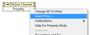
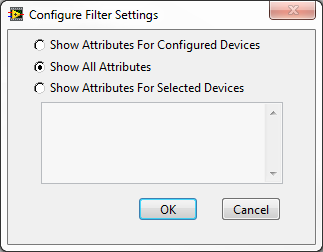
Option 1: turn off the property node filtered by right-clicking on the channel property node, by choosing "Select filter...". "and then selecting"display all the attributes:
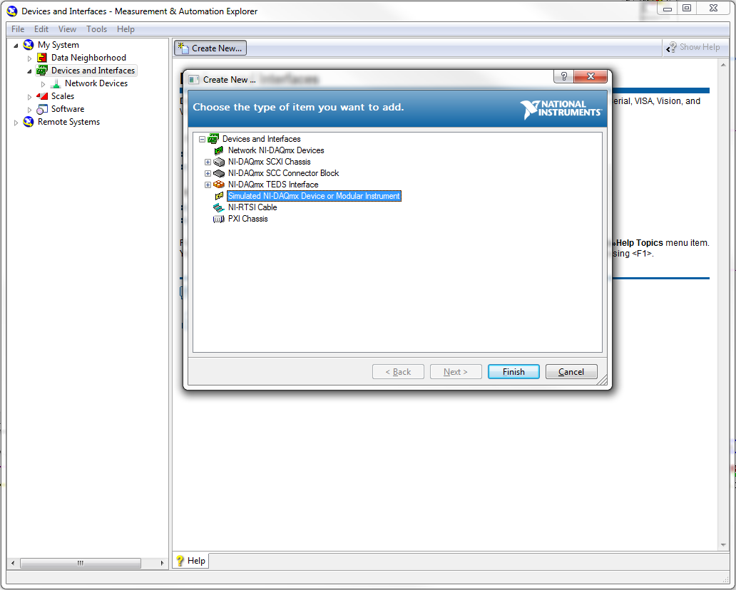
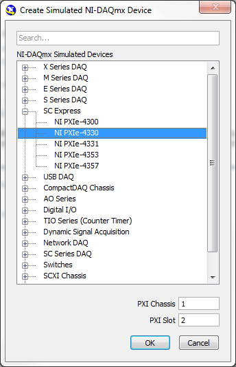
or Option 2: install a real SMU-4330 or simulated in your system. You can install a device simulated through the program of Measurement & Automation Explorer (MAX):
-
NI USB - 6259 BNC DAQ: analog input signal cross on the question
Hello
I use the NI USB-6259 BNC DAQ unit to acquire a four-channel analog signal, and I'm having a problem with a signal that affect others. The circuit, I am running is:
I have a wire connected to a battery (two AA batteries at ~1.5V), which then feeds the signal cable to a BNC cable, which feeds an analog BNC of data acquisition channel. The field of NBC feeds to another wire, which is attached to a conductive plate. The idea is this: when I touch the wire connected to the battery for the metal plate, I complete the circuit and thus get a binary not anything at all about 3V. When I tested with an osciloscope using two channels (each earth connection to the metal plate) I get independent steps whenever I touch any of the sons of the respective batteries to the metal plate (i.e. it works as expected). However, when I use it with data acquisition, whenever I touch a wire, I get a response in all other channels (3 others), even if their respective sons does not touch the metal plate.
No one knows why this happens, and how I might be able to stop this 'cross-talk '?
Thank you
Veritas
I see, and you're right. This request will have trouble with crosstalk. Luckily the ground channel thing should help you.
Configure your DAQ to collect twice as many channels as you need. Connect your wires in the odd channels and short circuit (ground) the entries of those even.
Now when you scan the channels it will always technically crosstalk, but it will come from a channel to the ground so that there will be nothing to interfere with your measurements.
At least that's the theory.

-
Lack of external function DAQ channel read
Hello
I did a few installers to share on the network variables, one is based at DAQmx readings of analog channels use modules of simulations and the second donkey receives variables shared these radings... I thought it was pretty good, because I have the main application (channels read and share variables) in my main PC (which has istalled LabVIEW 2012) and the other track in a regular PC (no software OR installed until my Installer Act) and it worked fine. However, I installed the main application in the regular PC and I got an error stating: lack of external function DAQmx read single sample DLB... I guess I should include in my Installer features on DAQmx but I Don t know which ones to avoid this error and be able to install my apps in any PC... Thanks I await your advice!
Well, I found the solution...
I've just included confiuration NI DAQmx MAX support to my app Installer and I solved the problem...
-
Determine the number of channels selected for traditional DAQ
The blocks 'DAQmx task' and "Traditional DAQ Channel" look pretty similar (see attachments). The DAQmx block ist an individual selection of channels and I am able to determine the number of selected channels.
Now I am trying to determine the number of selected channels to a traditional DAQ, but the property DAQmx block does not work here. I already tried the trad to some form of blocks. Range of data acquisition, but failed.
Any idea?

In traditional DAQ, there are several ways of specifying the list of channels. Assuming that your picture shows how you use your channel list is just a string of delimited by commas. Wire a constant to a string array node worksheet and specify "comma" as the separator and the number of columns must tell you the number of channels.
Ben
-
NI USB - 6212 BNC analog input impedance matching
I just ordered a case NOR USB - 6212 BNC DAQ (should be delivered soon). I want to use to measure HV signals using a probe of high voltage of 1/1000 I have.
Now, datasheet of the probe (not a lot of info) says it has an impedance imput 100MOhm. I suppose that it consists of a simple resisitve divider, and if the ratio is 1/1000, I wait so to have a 99.9MOhm resistance in series with a 0.1MOhm resistance. However, the data sheet also specify that the probe is designed to be connected to an oscilloscope with an impedance of 1MOhm. As this input impedance is very low compared to the low value of the separator of resistance resistance, so I guess that the real resistance at the level of the sensor values 99.9MOhm and 0.11MOhm (to obtain the 0.99 and 0.1MOhm when it is connected to the oscilloscope for 1mW).
Therefore, given that the impedance of the USB-6212 according to the datasheet, the analog input is > 10GOhm, I expect to measure higher to true alternative voltages when connected to the acquisition of data from 10%. This assumption has a meaning?
What would be the best way to get around this? Do a calibration and correct the values acquired in LabVIEW code? Or should I add precision 1MOhm resistance at the same time to the acquisition of input data to decrease its resistance to entry to the value expected by the probe?
Thanks for your help!
Since you have a range of 1000: 1 I guess you also need bandwidth (I have a TEK 6015 A
), so you need based on the impedance input, a complex value, means he must not only watch but also the ability to input resistance (1 M). demarcation of the field probes have usually some elements of toppings to match the probe and the input scope. RTFM of the help of the probeBUT a more serious point is that with your probe, you have a very high resistance. And if you look in the specification of the 6212 you will find on page 2 by mistake ppm in logarithmic scale graph! and even 100 k source impedance it not shown.
So I'm afraid that a simple 1 M on the DAQ entry can work if you're only measuring DC, and only if you use a channel on the acquisition of data. A workaround is an amplifier separate buffer with an impedance of good entry corresponding to the specification of your probe and a low output impedance.
-
How can I get the USB-Quad08 with Dasylab encoder channel data
Hello
I'm reading the pulse signal of USB-Quad08 with Dasylab V10, but every time I got the error message "this Committee has no meter 9513.
I have configured the jury with Instacal and the test hardware is ok. I used the module 'Entry meter' (Modules--> inputs / outputs--> MCC - DAQ--> Counter Input) to read the signal of the channel meter. "Entry 9513 counter" displayed and I na not change settings. After connecting a graphic recorder module I run the application. The error message appeared.
I noticed that USB-Quad08 Council has counter 9513. But why the error occurs? How can I get his channel encoder signal?
PS. I can get with Dasylab DIO signals, but I can't any signal with TracerDAQ, even I can't find USB-Quad08 in his list of DAQ devices.
Please contact Measurement Computing.
-
Configure a load cell connected to multifunction DAQ
I'm trying to connect a LCDH Omega 10 K scale by a module of constraint Dataforth SCM5B38-37 then AI0 gauge on a USB-6251 multifunction data acquisition.
In addition to the load cell, the application will use a pressure sensor with a strain gauge bridge module plugged into AI1 to read the pressure of hydrulic. The pressure transducer using a measure of the force will be calculated and compared with the reading of load cell.
Currently, the USB-6251 box is configured to read analog voltage on AI0. The scale is then performed using linear Fit.VI.
Review the example Bridge - entry continues shows some additional controls may increase the accuracy of the reading.
Unfortunately trying to use the DAQ Assistant only added to my confusion of the best practice in the acquisition of a signal from a load cell.
__________________________________________________________
Here are some of the questions I have...
What is the best practice implement a load cell using a full bridge strain gauge conditioning module labview?
What is shunt calibration? Is this similar to the USB-9237 DAQ modules-specific?
How do you know if your sensor is set up like a full bridge, half bridge, etc, the document load cell does not it?
You can use the VI delete DAQmx perform bridge?
_________________________________________________________________
I don't know, I understand all the information of the map calibration either.
Why is there resistance to entry and exit values?
What is the value of the zero balance signafiance?
Specifications of load cell
Lbs mV/V
0.000 0
2000 0.598
4000 1,201
6000 1,804
8000 2,404
10000 3.002
Excitement: 10 VDC
Input resistance: 350,41 Ohms
Output resistance: 352,08 Ohms
Balance zero: 0.01 mV/V
Hello!
I was looking into your question and found a few links that might help you configure your system. The first is a white paper that discusses some of the basic concepts of the gauges of constraint and their use with LabVIEW, shunt calibration and also covers some of the resistance values you see:
http://www.NI.com/white-paper/3642/en/
As you can see in this article, we have some specific hardware, built for the kind of measures you take. Because these devices are manufactured specifically for this application, they would provide better and more reliable results. That being said, you can configure your system with your USB-6521, it might not be as accurate as one of these systems. To set up your measurement system, rather than defining the analog input as a measure of deformation, you want to use the voltage custom with the option of excitement. This article treats this yet:
http://digital.NI.com/public.nsf/allkb/C66F92BDE229F45A86257B6D004D6033
We get you your data in the form of Volts/Volts (this document addresses more info on bridge probe scaling: http://zone.ni.com/reference/en-XX/help/370466W-01/measfunds/bridgescaling/), , but you should make sure you standardize this value to the excitement. Devices such as the NI 9237 provide the voltage and can take this known value in to account within the program, but you may need to do this manually for your application. Here is additional information on the NI 9237 and how it is configured to read information from strain gauge:
http://digital.NI.com/public.nsf/allkb/892C84122A6501AE86257547007E5C53?OpenDocument
Regarding the configuration of unit load and the information, you can try to contact the manufacturer for more information!
Thank you!
-
DAQmxWriteDigitalU32 writes zero channel
I learn to use NIDAQmx in my process control project and am stumped with my problem. I'm using LabWindows CVI 8.5 and PCI-6229. Here is the code segment causing problem
----------------
OUTPUTS DIGITAL DAQ 0-23 reserve line
char chanP1Leds [] = ' dev1/port0 / line0:2 "; RGY
char chanP1TestClr [] = "line12/port0/dev1;
char chanP1AirCtl [] = "line16/port0/dev1;Line reserve DAQ DIGITAL INPUT 23-31
char chanP1TestIn [] = ' dev1/port0 / line30:31 "; 30: test, 31:retestAnalog data acquisition
char chanP1RegMon [] = ' dev1/ai0; Pressure regulator monitor
char chanP1FlowMon [] = ' dev1/ai1 '; Flow regulator controller
char chanP1TransMon [] = ' dev1/ai2. Pressure sensor monitor
char chanP1PressureCmd [] = ' dev1/ao0 "; Pressure regulator control
char chanP1FlowCmd [] = ' dev1/ao1; Flow regulator control.
.
Sub GlobalInit (void)
{
int n;
SamplesWritten of Int32;
error int = 0;
char errBuff [2048] = {'\0'};
uInt8 TestData = 1;
uInt32 P1LedsData, P1AirCtlData, P1ClrData;
Inititialization data
P1SerNo = 0;
P1PressCmdData = 0.0;
P1FlowCmdData = 0.0;
P1FlowMonData = 0.0;
P1PressMonData = 0.0;
P1TransMonData = 0.0;
P1LedsData = 0 x 7;
P1ClrData = 1; low-> Clear
P1AirCtlData = 1; low-> on
/*********************************************/
DAQmx Configure Digital Code
/*********************************************/
SetWaitCursor (1);
Digital outputs.
Channel LED
DAQmxErrChk (DAQmxCreateTask("",&P1TaskDOLeds));
DAQmxErrChk (DAQmxCreateDOChan (P1TaskDOLeds, chanP1Leds, "P1Leds", DAQmx_Val_ChanForAllLines));
DAQmxErrChk (DAQmxSetChanAttribute (P1TaskDOLeds, "P1Leds", DAQmx_DO_InvertLines, 0));
Test channel
DAQmxErrChk (DAQmxCreateTask("",&P1TaskDOClr));
DAQmxErrChk (DAQmxCreateDOChan (P1TaskDOClr, chanP1TestClr, "P1Clear", DAQmx_Val_ChanForAllLines));
DAQmxErrChk (DAQmxSetChanAttribute (P1TaskDOClr, "P1Clear", DAQmx_DO_InvertLines, 0));
Solenoid Air input control
DAQmxErrChk (DAQmxCreateTask("",&P1TaskDOAirCtl));
DAQmxErrChk (DAQmxCreateDOChan (P1TaskDOAirCtl, chanP1AirCtl, "P1AirCtl", DAQmx_Val_ChanForAllLines));
DAQmxErrChk (DAQmxSetChanAttribute (P1TaskDOAirCtl, "P1AirCtl", DAQmx_DO_InvertLines, 0));
Digital inputs.
DAQmxErrChk (DAQmxCreateTask("",&P1TaskDI));
DAQmxErrChk (DAQmxCreateDIChan (P1TaskDI, chanP1TestIn, "P1Test", DAQmx_Val_ChanForAllLines));
DAQmxErrChk (DAQmxSetChanAttribute (P1TaskDI, "P1Test", DAQmx_DI_InvertLines, 0));Activate tasks
DAQmxErrChk (DAQmxStartTask (P1TaskDOLeds)); Start the task output
DAQmxErrChk (DAQmxStartTask (P1TaskDOClr)); Start the task output
DAQmxErrChk (DAQmxStartTask (P1TaskDOAirCtl)); Start the task output
DAQmxErrChk (DAQmxStartTask (P1TaskDI)); Start the task entry
/*********************************************/
DAQmx write code
/*********************************************/
DAQmxErrChk (DAQmxWriteDigitalU32(P1TaskDOLeds,1,1,10.0,DAQmx_Val_GroupByChannel,&P1LedsData,,));
DAQmxErrChk (DAQmxWriteDigitalU32(P1TaskDOClr,1,1,10.0,DAQmx_Val_GroupByChannel,&P1ClrData,,));
DAQmxErrChk (DAQmxWriteDigitalU32(P1TaskDOAirCtl,1,1,10.0,DAQmx_Val_GroupByChannel,&P1AirCtlData,,));
DAQmxErrChk (DAQmxWriteDigitalScalarU32(P1TaskDOAirCtl,1,10.0,P1AirCtlData,));
DAQmxErrChk (DAQmxWriteDigitalLines(P1TaskDOAirCtl,1,1,10.0,DAQmx_Val_GroupByChannel,&TestData,,));-----------------
My problem:
1 DAQmxWriteDigitalU32 writes correct data.
the 2nd & 3rd DAQmxWriteDigitalU32 wrote zero in the channels and it does not matter where to move these 2 lines, they always write zero to the channels. The commented DAQmxWriteDigitalScalarU32 also written zero to the channel, but the DAQmxWriteDigitalLines writes the correct data to the channel. MAX test Panel also records the correct data in the port. I really don't understand why this is happening if I need your expert help to point out what I'm missing here.
Thank you very much.
Lanny
That's all. Thanks Brooks.
I have read the help file on DAQmxWriteDigitalXX and the format of data in the reference OR DAQmx and not to do so until now with your explanation. I guess the WriteDigitalLines throw me in a loop of thought DAQmx is masking and transfer of data to write the correct value in a port for other types of writing (and reading). A sample with lines and spots scattered around the port, as my case would save a NOR-DAQmx beginner like me a few days of agony. Well, we had the example here now.

-
I use several DAQ assistant but it seems impossible...
Hello world
I'm on a project for some time.
To summarize, I had 3 modules for the project: Anolog, digital, input resistance meter.
My main program works, but now I have to connect with an excel file.
I found an easy way of this solution, but now my problem is bigger. The fact is that I use my screws and screws with this how to link my data, but according to LabVIEW Sub, I can't, in the same program, do something in relation to 2 modules different. Obviously, each module works with a DAQ Assistant.
To be more specific: I want to put the data from the 2 (thanks to the analogue of the module), and wire different sensors 1-> 0 or 0-> 1 (thanks to the digital module)
And when I link 2 DAQ in the same file or 2 screws secondary who got 1 acquisition of data in entry of a measurement file, it does not work. The error that I can not launch the DAQ second after the first... so...
I hope you understand my problem.
You have a solution for this problem? Should I change a large part of my program to do this or is it just a small detail?
Thank you in advance! I'm really disappointed-_ - I'm for several times... and I'm late for my project...
Best regards.
ML
Maybe you are looking for
-
Tracks with a star - what it means?
I know the meaning notes have been removed, but a few songs at random by the album has a star next to them, now that I have updated to iOS 10.0.1. Anyone know what they mean and how
-
I don't know how to set the home page of the Initial screen on startup of Firefox, but every time I open a new tab, that it opens as a blank page. I want to set the home page for all new tabs that open (just like we have in Internet Explorer). This h
-
accounts not blocked, no answer for the account recovery after 24 hours
I am the user of * address email is removed from the privacy *, who was blocked yesterday because someone sent a large number of spam. I followed the account recovery process and seized the agent information to recover my account. But after wating fo
-
New dv5-1235dx: showing 2 hard drives, 1 CD player and 1 DVD player
I bought a new laptop dv5-1235dx last week and while I obviously only have 1 disk drive, I shows that I have 1 drive (F) and 1 DVD RW (E). Displays Device Manager only 1 drive installed, and CD & DVD appear on the drive from DVD (E). I downloaded & i
-
We have tried to add the article of personal menu in 6.0 (torch) and BB doesn't show any element: if (blackberry.ui.menu.getMenuItems().length > 0) blackberry.ui.menu.clearMenuItems(); var item = null; item = new blackberry.ui.menu.MenuItem(false, 3,