Data of measurements
Hello
When you use for example the tool area (but also applicable to the perimeter) to measure the area of a square to say, as you walk around and click on every corner, gives you the distance of the individual line that you just measure. However, once you make the final click to finalise the extent of the region, I don't see anyway to then recover the data indicating the distances of each individual line. If you click on the square, you can see the 'nodes' on every corner. but that's all. Anyone know how to recover this data?
A second question, does anyone know if you can overlay one PDF on another? I want to do is to superimpose an image 'ghost' of a consolidation plan on another construction plan (e.g. level 2 overlay on level 1).
Thanks in advance,
Neil
If you want to place it manually, you can use a stamp, but then you have not all smart properties such as opacity...
Tags: Acrobat
Similar Questions
-
B1500 read data while measuring
Hello
I'm trying to control my B1500A. I need to read some datas all B1500 measuring.
All the drivers are provided with a reading after finished measurement. I cannot read the buffer before the end of the measure.
does anyone know how to do this?
Thank you very much
Claire
-
At what level is the store of data latency measured?
Hello
I have a question about latency of data store. I see that, generally, 20 to 30 ms latency limit before having the performance issue, but at what level is this limit? It is the seat of the latency of the VM? See vsphere?...
In Vcops, when I select a data store and access operation - details see read/write latency: see comments AVG or device AVG? (see image below)

When I select a VM in Vcops to see the latency time "of virtual machine", what is the difference between latency vDisk and the VM latency data store?


I know there are a lot of questions in one thread, thank you in advance to those who take the time to answer.
As esxtop counters, you have different counters to measure different parts of the stack. If you have latency at a disk level your queues will be filled and reflected. Latency of disk order is good enough to pick up underlying storage latency, but it depends what resource you are watching. The attributes derived from 'latency' exist here and there which are calculated based on the type of storage/etc to simplify your life and give you one place to search.
When you start to look at the latency of the queue, you must keep in mind that focuses only on the queue. Take a look at the Duncan article (ESXTOP - bricks yellow) on it and your questions will probably be kept clear with regard to what are the bits/s and for the disk counters.
-
Point cloud with missing data and 3 sets of data
Hello
I'm doing a scatter diagram that has 3 sets of data in it (i.e. 3 plots on the same graph), except that 2 of my sets of data have a missing value while my third set has all the values. I end up getting 2 lines that are disconnected. I can't just remove the line containing the missing data for the 2 sets of data because since my category axis is time, my data points get shifted and no longer appear at the right time. This is the chart that I have.

Thank you.
Hi Gabrielle,.
If there is a diagram of dispersion, the x axis is a value axis. If you have auto selected for the min and max values on this axis, the scale may change when you remove the data point, 15, 85, but the rest remains in the same position relative to the values on each axis of ordinates. What change will be , however, is the curve on which 15 85 approached a local y maximum.
Scatterplots will always leave a gap in the line/curve of connection where there are a pair of missing data. There are two ways to close the gap.
If the chart is an essentially linear relationship, you can use a calculated value is pair up with the lack of value x. The downside of this is that the representation of this point will be indistinguishable on the map of the other data points, measured.
A better way would be to make two tables, one with the full data set, the other with the partial sets, but with the pair missing completely removed.
Adjust the cards the same size and have the same scales on each axis, then just remove one of the cards except the data points, the curves connecting the data points, the x axis of ordinates and the legend showing the color and the forms used to plot each series.
Give a graphic a transparent filling and place it in front of the other.
Kind regards
Barry
-
I use my Apple Watch in 'training' mode but want to use the info in other applications like Strava and Garmin Connect. I gave permission to these applications in the Apple Watch setting, but it is still not sync. I would also like to be able to carry my "data steps form the app health on Garmin, but not get anything to synchronize."
In the meantime I record only in 'training' and Strava. This of course does nothing for data of measurements.
Any ideas on how to proceed?
Hello
Strava to Garmin Connect Mobile Developer support is available here:
- Garmin:
- https://support.Garmin.com/support/searchSupport/search.faces?refresh=true&Produ ctName = % 20Connect % 20Mobile Garmin
- Search for "HealthKit" and read this response: "How iOS HealthKit works with Garmin Connect Mobile?"
- The article suggests that the data are shared to Garmin Connect Mobile enforcement of health, not the other way around.
- Garmin:
-
manipulating data with several readings
Hi again,
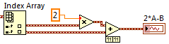
So I can read the tensions out of the terminals of NI USB-6009. Now was that reading analog1 and B be analog2 reading. I want to calculate something like 2 * A - B. I can't understand how to do this.
I can read the values together and watch them on the same chart, but I can't deal with them. I enclose the file in which I read the values, put them through the filters and then display. But 'data' is only one variable, although there are two readings in it. I do not know how to separate one from the other.
Thanks for the help.
cartonn30gel,
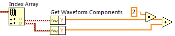
Playback DAQmx returns an array of waveforms, each element of the array represents a data channel.
To split the individual channels out there, use primitive Table of indexes in the table Palette:
You can then use regular numeric operations on the waveform, or if all you care is the actual reading, you can get the table of voltages measured waveform using the primitive to get elements of waveform in the waveform Palette.
Thicker wires in LabVIEW represent arrays that contain several similar items. The waveform data type is a convenient way to manage measurement data because it combines information in time (t0 and dt) with the data table measured (Y).
I hope this helps.
Simon
-
How to configure a lab overlooking tubular heat exchanger to get data
Hi
 I
IIn our undergraduate engineering chemical labboratory we want to configure our DAq with lab VIEW tubular heat exchanger to get information on the temperature (flow cold fluid warms up), (the steam pressure on the side of the hull of the heat exchanger) and flow (water warms up).
Can anyone suggest thermocouples, pressure transducers, and flow meters to stay between the heat exchanger and the acquisition of data?
P.S. the heat exchanger is already equipped with a pressure gauge, thermometers and a rotameter, but we do not know how to connect these devices to data acquisition
Looks like you have enough information to choose appropriate sensors, you just need to do the research. I start looking into Omega catalogue, or give them a call - they are generally useful. I can't take the time to spec parts for you - it would be a lot of time on another project. Most pressure sensors put a signal 4-20mA or 0 - 5V, that is which you can read through an analog input on a data acquisition; measure a 4-20mA signal requires a resistance to convert voltage. Most NI DAQ boards can read a thermocouple on an analog input, but make sure that your hardware is supported reading thermocouples. For an accurate reading, use a device that has the compensation of cold welding integrated - for example, the block connection SCB-68 - and for more accurate measurements, get a Board specifically designed to measure the temperature.
For measurement of the flow, a standard, simple solution is an orifice plate. You put a transducer for differential pressure across it, seek the appropriate equations and use them to calculate the flow rate given the density of the fluid (which you will be able to calculate from the pressure and the temperature, since the steam tables are widely available). Other differential pressure devices are available as well - at a previous job, we used a double cone of McCrometer. If you call them, they spec for you - but get an approximate cost first to make sure it's in your budget.
-
variables of user-defined data transfer
Hello
I use the etherCAT 9144 chassis and is only supported by this hardware FIFO range target. After a search, I realized that the only way to transfer data from FPGA to the host by using user-defined variables. But these variables do not support the notion of FIFO. So which is the best practice to transfer data after measures (provable 10 Hz measurement of 15 values) to host VI?
Thank you
As mentioned, the 9144 only supports the analytical engine.
In regards to what you do, it really depends on the entire application. For example, what is the master? Are there other systems at issue here? Etc. It's a good read, in general, although it might not help this second right: http://www.ni.com/white-paper/14151/en/
A high level, you need to decide what you need. If you have need for deterministic communication, low-latency over long distances from a RT controller, the 9144 is probably the right choice. If you need low latency + streaming over short distances to a RT controller, you should look into the RIO MXI chassis. If you need mainly not deterministic low speed (10 hz) data mixed with low flow continuous over long distances to a windows or host RT, then ethernet expansion rio (9146,7,8,9) is probably the right choice. If you need high speed continuous with low control latency over long distances to a windows or RT host, you need a full cRIO controller. Based on what you've posted so far, its uncertain is the right person.
Lets say you're stuck with the 9144 for now. As you can easily hit 1 kHz scanning cycles, it should be perfectly possible to data 'stream' to 10 Hz. If you run the scan at 1 kHz engine, then you are 100 x oversampling. Where it gets complicated is this requirement of sync. By default, acquisition input/output is synchronized to the clock of the scan (and you can see when the clock of scan is set by a knot of e/s FPGA). However, you can take complete control of a module in the FPGA and read inputs and outputs at any time if you please. In other words, you can set up so when DIO0 goes high you immediately enjoy all the values of AI 15. You can then transfer these values HAVE switched to the host using the user-defined variables.
-
Measure voltage across the thermistor outwardly excited
Hello
I'm looking to collect temperature data by measuring the voltage on an input temperature of a piece of industrial equipment terminal. A thermistor is currently connected to a Terminal, and my USB-6212 analog input terminal is connected in parallel. The equipment must remain functional, so the thermistor can not be deleted.
The problem is the USB-6212 disrupts significantly far - for example, the temperature of the equipment reading spikes of 45degF at 60degF whenever the USB-6212 is connected. Using a multimeter Fluke does not cause the same problem. I tried to measure the input impedance analog for the USB-6212 with a Fluke 87 - III. I get out of the range (> 50 M Ohm) with the lit 6212 and ~ 12 M Ohm in judgment. It seems to meet the specifications and should be high enough to not to disturb the measurement. I do not know the side of the probe, but estimate it's about 20K ohm based on measures of tension DMM with and without parallel resistances.
Can anyone suggest a way to solve this problem, or another way of measuring? The main constraint is that the thermistor must remain in the terminal of the temperature.
Thank you
Leo
Leo,
It's only a guess, but a guess a little.
Two clues: not measured with a multimeter is no distuirb the result. Measure with the USB-6212 disrupts the result.
The DMM is probably battery powered and not connected to any reference to the ground. Certainly, the USB device is connected to the USB ground which in turn is connected to the mass of the computer.
My guess: a ground loop between the acquisition of data/USB/computer and industrial equipment. Unless the industrial equipment specifies that one end of the probe is grounded and the reasons for the equipment and the computer are connected to the same point of mass, it will be difficult to measure as you described.
Things to try:
1. with the help of the DMM measure the voltage (AC and DC) between each end of the probe and the mass of the equipment.
2. with data acquisition/computer disconnected the measurement equipment (DMM), tensions between the computer or ground DAQ and the mass of the equipment.
3. If all the voltages measured in 1 and 2 are in the specification of common mode for entry for the DAQ hardware voltages, then try a differential connection with polarization adapted ground resistances.
Do you have a technical manual or diagrams for Brad equipment?
Lynn
-
Problem with registration of data in the txt file
Hello
I have 2009 Labview, Labview real-time 2009 and cRIO 3.3.0. I also NEITHER cRIO-9024 more cRIO-9112 chassis and modules.
I would like to save the data measured modules in the txt files, but I want to do in a period of time to time desire. For example, I want to save data of measurements of 60 seconds and repeat every one hour. I of the project (in the file attachment vi) and normally it works fine but I noticed that the recording of the data is not correct. I mean it seams to save what was in the memory before. That's the problem with Windows XP I have check with another computer with Vista and it seems to be ok. It seems that on XP the buffer (refnum?) is not clear and it retains the previous values.
Can someone explain to me why it happened and how I can obey Windows XP? Or maybe there are techniques to clear the memory buffer/refnum for rescue?
Thanks for any help.
Kind regards
Kamil
-
Sends data to a VI to the other
My test application consists of several VI. One of them is just to enter/modify test information, for example the tester name, date, HAD model names and numbers etc. Another is for entering the data of test equipment (serial numbers, calibration due dates, names of resourse VISA etc.). Third is to measure parameters (frequency, power limits, calendar, etc.). And I VI Reporting using the data entered, measurement and Calibration.
What is the best way to communicate between these VI? I use global variables, but every now and then I read in this area and other forums that abuse variables is a bad habit and should be avoided.
The best way is to use the wires in cases where data dependence created by the son is accepatable. In your case it is not only acceptable mandatory weed. You cannot run the test until the parameters entered.
I propose an architecture of State machine with States who call the subVIs. Data can be passed on from one State to the other shift registers.
If parallel execution is required for some parts of the show, then wiring will not work. A global variable functional or engine of the Action can be better for global variables. Queues are also a good way to pass data to a parallel loop.
Lynn
-
XML data. Extraction of elements and attributes using Xpath or another?
Hi experts,
With the help of Oracle 11 g.
I have an XML table that stores XML in a column (xml_col) like the structure below.
Example:
I tried constantly to run XPath queries on this column to get the node < element > attribute data and the value of the < value > node in.<measure id="abc"> <data-elements> <data-element id="ab"> <value>40</value> </data-element> <data-element id="cd"> <value>8</value> </data-element> <data-element id="ef"> <value>38</value> </data-element> <data-element id="gh"> <value>32</value> </data-element> </data-elements> </measure>
My goal is to turn this into a table of:
AB | 40
CD | 8
EF | 38
GH | 32
My mind is stuck on him doing this below and dressing with a CSV file to query hierarchical lines. I can't convert xmltype in chain to do this work so.
But I get the following error:select str1,str2 from ( select extract(xml_col, 'string-join(//@id, '','')') str1 ,extract(xml_col, 'string-join(//value, '','')') str2 from xml_temp_table) CONNECT BY LEVEL <= LENGTH (REGEXP_REPLACE (str1, '[^,]+')) + 1;
ORA-31011: XML parsing failed
ORA-19202: an error has occurred in the processing of XML
LPX-00607: Invalid Reference: "string-join".
I am looking for a solution not PL.
Any suggestion is appreciated.
Thank you
Published by: chris001 on February 26, 2013 12:06
Published by: chris001 on February 26, 2013 12:07chris001 wrote:
My mind is stuck on him doing this below and dressing with a CSV file to query hierarchical lines. I can't convert xmltype in chain to do this work so.Oh boy!
This should relieve your pain ;)
SQL> select x.* 2 from xml_temp_table t 3 , xmltable( 4 '/measure/data-elements/data-element' 5 passing t.xml_col 6 columns element_id varchar2(10) path '@id' 7 , element_val number path 'value' 8 ) x ; ELEMENT_ID ELEMENT_VAL ---------- ----------- ab 40 cd 8 ef 38 gh 32 -
How to show the extent of the day and date a month before her?
Experts,
I have a list of dates and measures. If I select a date from the calendar (as a command prompt) prompt, there bring it records of this date and the date of the month previous (reduce the 30 days of the date of the day). I have no idea on how to proceed with this requirement. Any help is appreciated.
I'm using OBIEE 11 g.
Kind regards
LIBERATORManon says:
Experts,I have a list of dates and measures. If I select a date from the calendar (as a command prompt) prompt, there bring it records of this date and the date of the month previous (reduce the 30 days of the date of the day). I have no idea on how to proceed with this requirement. Any help is appreciated.
I'm using OBIEE 11 g.
Kind regards
LIBERATORIf you are looking for two dates, the date of the command prompt and a "30 days prior", then follow these steps:
(1) create a dashboard on the date column and assign a TICKET called pv_Date.
(2) in your report, put a filter on the same date column:
table. "Date = ' @{pv_Date}"
OR
table.date = TIMESTAMPADD (SQL_TSI_DAY-30, TIMESTAMP ' @{pv_Date} "")If you wanted to say: 'all values up to 30 days before the maximum value of the line,' enter the following:
table.date BETWEEN <= '@{pv_date}'="" and="" table.date="">= TIMESTAMPADD (SQL_TSI_DAY-30, TIMESTAMP ' @{pv_Date} "")
-
Limiting the visibility of the data by the owners of scenario
I know that the security filters can make measurements read-only for a particular user.
What is the best practice to restrict a user or a subset of users to be able to see a part of an application, but not part of the application (example: American planners want to see the list of the United States, or a subset of the American list, but do not want to see the data for the EMEA or APAC). What is better controlled with several cubes, or is it a form any safety or other device to prevent users or owners of the scenario to see other data of areas?
Thank you.Security filters can be defined at a cellular level, and available permission settings are no access, read-only and read-write. So if you set the American planners access to EMEA of lack of access data, they see no data to measure associated with the part of the EMEA of the dimension.
Is it that addresses the needs?
-
import channels plan DAC fails
(Sorry if I have a few names of block etc. not quite right;) I use the German version of DIAdem, where all names are translated)
Hello
I have a DAC scheme that needs to read two channels of digital data from the data portal and perform processing on these channels. The reading is done using the package treatment "read data" block. for debugging purposes, I have a "scope" connected block package to this block "read data". In parallel to the scope block, the data is sent to an external measurement system.
When I put the channels that I want to address in the data portal and manually start the measurement (using the green button "Start the measure" in the toolbar of the CAD), the content of these channels is displayed in the scope, measurement system receives the data correctly and the DAC system works as expected - so in principle everything is correct so far.
Now, all this must be controlled from a VBS script. This VBS script first runs the data portal, then wrote my two channnels in the data portal and finally loads and starts the DAC system (call SchemeLoad (...): call SchemeCheck ("Normal"): call MKSCheck (0): dial the SchemeMeasStart()). In doing so, the system fails, I do not see in the window of the scope of data and measurement system receives no data at all - as if no data was never read from the data portal.
When I wemove the 'SchemeMeasStart' command (which is currently the last command in the script), run the script and then start the measurement manually using the button "Start the measure" above, everything works well again.
So it seems I have a problem with access to channels of data when the DCA plan is started from a script. In I made a mistake here (e.g., lack of some script commands based on the DAC)? Or is this a known bug, and does anyone know a solution for this?
Hello
I created my own example in ball mode. Everything worked without problems. The script does not use the MKSCheck command. It seems that this command is not necessary to run a CAD program. When I added the MKSCheck manually, I had the same problem with the packages blocks.
Since ball does not use MKSCheck, it must record this command simply jump and your DAC plan should work as expected.
Ulrich Bierwisch


Maybe you are looking for
-
Cannot update firmware for nex5 - checked all of the below problem but still the same
-
0211 keyboard error, press F1 to continue
I was running a spybot check & when I got back to laptop it was empty. Nothing worked so I let electricity run out & when restart got the error keyboard 0211 press F1 to continue so I did. When I tried to log in to my user account, nothing happens wh
-
Print a page in the notebook print Menu
I have Windows 7. In Notepad, print option indicates 'selection' and 'pages' gray. Therefore, you cannot print a specific page. Why list them all if they are not available in Notepad?
-
Anyone having problems when you try to close a document in Acrobat DC (15.017.20050) when running Windows 7?Try to close a document - or leave the program with an open document seems to lose there mind.Acrobat DC does notHave this question last week
-
HelloI have an interface in ODI with a "AGGREGATE". I uses this component to extract the separate lines with the function MAX (column), that it works perfectly for a record, but my LKM don't work line by line and a single record from...I need to run