Measure voltage across the thermistor outwardly excited
Hello
I'm looking to collect temperature data by measuring the voltage on an input temperature of a piece of industrial equipment terminal. A thermistor is currently connected to a Terminal, and my USB-6212 analog input terminal is connected in parallel. The equipment must remain functional, so the thermistor can not be deleted.
The problem is the USB-6212 disrupts significantly far - for example, the temperature of the equipment reading spikes of 45degF at 60degF whenever the USB-6212 is connected. Using a multimeter Fluke does not cause the same problem. I tried to measure the input impedance analog for the USB-6212 with a Fluke 87 - III. I get out of the range (> 50 M Ohm) with the lit 6212 and ~ 12 M Ohm in judgment. It seems to meet the specifications and should be high enough to not to disturb the measurement. I do not know the side of the probe, but estimate it's about 20K ohm based on measures of tension DMM with and without parallel resistances.
Can anyone suggest a way to solve this problem, or another way of measuring? The main constraint is that the thermistor must remain in the terminal of the temperature.
Thank you
Leo
Leo,
It's only a guess, but a guess a little.
Two clues: not measured with a multimeter is no distuirb the result. Measure with the USB-6212 disrupts the result.
The DMM is probably battery powered and not connected to any reference to the ground. Certainly, the USB device is connected to the USB ground which in turn is connected to the mass of the computer.
My guess: a ground loop between the acquisition of data/USB/computer and industrial equipment. Unless the industrial equipment specifies that one end of the probe is grounded and the reasons for the equipment and the computer are connected to the same point of mass, it will be difficult to measure as you described.
Things to try:
1. with the help of the DMM measure the voltage (AC and DC) between each end of the probe and the mass of the equipment.
2. with data acquisition/computer disconnected the measurement equipment (DMM), tensions between the computer or ground DAQ and the mass of the equipment.
3. If all the voltages measured in 1 and 2 are in the specification of common mode for entry for the DAQ hardware voltages, then try a differential connection with polarization adapted ground resistances.
Do you have a technical manual or diagrams for Brad equipment?
Lynn
Tags: NI Hardware
Similar Questions
-
best way to measure the thermistor
Hello!
We are looking for a solution for measuring temperature thermistor. I've read the material resources OR recommend for the thermistor measures.
Can you give me some ideas other alternatives for usable material temperature through resistance (we would use the default configuration, excitation of 2.5 Volts and a resistance of 5 + thermistor). So we need something capable of giving 2, 5V output and to measure the tension caused falling across the thermistor.Would be a NI USB-6009 suitable for this task? I guess that the resolution is not enough maybe?
Another option might be cheaper with a USB-GPIB interface Keithley 2010 multimeter, but in this case what should we use as a reference of tension?Thanks for the tips!
I want to second opinion to Henrik about repeatability in high resolution. Measures of temperature with Thermistors are particularly difficult. You have to worry:
- Auto-echauffants because of the power generated by the excitation current
- Time to balance the thermistor and electronic
- Stability of the excitation source
- Stability of the measuring device
In general, if you want something more than about 1% reproducibility, things start to me interesting. Of course, it's what makes it fun to do.
If you go the road of the sound card, remember that while most modern computers have quite high resolution a/d (sometimes up to 24 bits at 96 kHz) converters, you must watch the noise figures to get what you can actually solve. Off-board solutions (e.g., M - Audio Delta 44) will give you the best numbers of noise, since the ADCs are isolated from noisy inside your computer.
Good luck and have fun.
-
excitement of the thermistor and NI6224 DAQ board / whatever it is quick and (relatively) cheap?
Hello world
I need to measure temperatures between 15 ° C to 40 ° C and to resolve precisely the changes in 0.1 ° C. My thermistor has a nominal resistance of 22 kOhm at 25 ° C and the resistance of 14 KOhm at 37 ° C. constant dissipation in air at 25 ° C is 0.3 MW / ° C - but the thermistor will be used in aqueous solution. I have a NI6224 DAQ card with a connector in SCB-68 and Labview 7.
How do my NI6224 work with my thermistor with minimal cost?
In particular:
the NI6224 has no analog output. Can I use a digital output as a power source? I would say no because the current digital output is 24 mA, it would make my time 14 KOhm > 10 V, which is the input of the Board of Directors range 24. Is this correct?
I could buy a module NI 9265 + chassis + cables etc to provide the excitation of the thermistor current and connect his two sons to a Council NI6224 differential voltage input? Y at - it any cheaper option with others OR or equipment of third parties?
Thank you in advance for your time and help
(Note that this message was posted in response to another thread named "thermistor". I'm following the suggestion to move here in a new thread to increase visibility and try and get help...)
Yes.
You are correct about both measures ended up alone. The other end of the probe will be connected to the Earth.
There is no advantage to a measure differential in this situation because there is no true differential signal. The two voltages are referenced to ground.
Calibration is always a good idea. Here, he will compensate for differences of Thermistors and fixed any deviation from the nominal value of the resistance.
Even if your temperature is probably change very slowly, it can be useful to sample at a rate groups and average high of samples to produce a single reading. This can considerably reduce the noise. A common source of noise is the electric current. By sampling at a multiple of the line frequency of power, such as 1200 Hz and then with an average of 1200 samples, you get a reading per second with substantial reduction in 50 or 60 Hz noise.
Lynn
-
Differential measurement across the ground of the card NOR referenced output.
Hello guys,.
I have a question, our pure curiosity.
I use map of USB6212 to apply a sinusoidal signal of 10V to a game to the top, then measure the tension between charges.
I'm attching here a simple diagram showing the system. The implementation can be modeled as a combination of RC - r series
Note that I'm also measure voltage R2 in differential mode. Now that I am after is exact phase of monitoring between the two voltages (according to the RC and the R2).
My question: is the correct diagram? I mean - is it OK to measure the voltage across R2 in differential mode with attached as such polarization resistors?
It is one of the lines through R2 is already at AOGND. And AIGND and AOGNd are already connected inside the card, it will be then introduced errors?
or does not at all?
Thanks guys, will be grateful for a quick solution.
You can do this but the differential mode does not have much. Your signal source is single ended. The voltage at the terminals of R1 - C can be measured in different ways. It really is meaningless to measure the voltage across R2 differently because one end is connected to the Earth. Polarization resistance, Rb, are not necessary in this case because the low enough impedance DC railways exist at all entrances.
What I would do, is make two measures ended up alone. AO1 measured on a single channel (AI0). Measure the R1 - R2 junction on the other channel (AI1). Then the input voltage is AI0, the voltage at the terminals of R1 - C is AI0 - AI1, and the current is AI1/R2. You will need to enjoy fast enough that the time between the different measures does not contribute too much to the phase error. It depends on your frequency of signal and eligible errors. Look at the charts of a waiting time to page 2 of the NI USB - 620 x specifications for more information on how to compromise between the speed, accuracy and multichannel source on measures resistance.
Lynn
-
Measure the voltage and the temperature simultaneously with PCI-6281
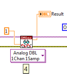
Measure the voltage and the temperature at the same time at the same time. However, when I put the voltage and temperature in a loop, the acquisition of voltage is significantly delayed. When I put the voltage and temperature in two different loop, none of them works. There is an example in aid of Labview as shown. This structure works fairly quickly? In addition, how a volgate get and temperature Analog DBL 1Chan 1Samp? I check the exported excel, the first column is 0, 1 the second column contains the value of the voltage, temperature value. I wonder how can I get these two values for each scan.
,
Assuming that the DAQ cards can handle it, you can set an analog trigger for the channel of the tension. Then you just X samples to get your 100us data value. Keep the last sample.
-
Measurement of voltage and the voltage with CompactDAQ display?
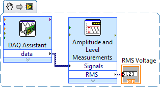
OK, I just got my CompactDAQ hooked up with two modules (9225, 9239) and am able to simple single-phase voltage (120 VAC)... I connected an indicator, and it gives me shooting random sine wave values and what I'm looking for a simple voltage reading. MAX and the DAQ assistant both work very well to the configuration task and I can see the signal in there.
I dug through the DAQmx, watched functions in the knowledge base and have searched here without any real results. I also downloaded the EPM resource kit, but it's tools for further on the road... It seems to me that this should be simple crazy, but maybe I go too hard or just looking is not in the right place? I would greatly appreciate a point in the right direction!
Thank you!
Chad
With the help of... Windows XP (SP3), LabVIEW 2009, cDAQ-9174, 9225, 9239.
Chad,
When you say "simple voltage readout" are you referring to the effective voltage of the AC signal? If Yes, you can use the Express VI 'Amplitude and level measures' to calculate the desired value.
Hope this helps, otherwise if specify you what you are looking for a little I will try again.
~ SimonH
-
Hello people,
I've read several documents on the site OR about the premium over common measures of mode and I think I understand, but I'm looking for confirmation through two examples (please).
Both examples assume a data acquisition card OR with +/-10V inputs and a maximum operating voltage of + / 11V (e.g. PCI-6052 with programmable gain 0.5).
Example 1: Suppose a DC voltage with two resistors divider and a differential input on the daq card configuration. First resistance = 4 Ohms connected to 100VDC, second resistance = 96 - grounded (0) Ohms. This results in a decline of 4VDC to the terminals of the first resistance. However, I believe that the differential voltage of 4VDC may be connected directly to the daq card because the absolute voltage (i.e. common mode?) is in fact 96VDC to 100VDC which is outside the "working range' of + / 11V for the card. This conclusion is correct?
Example 2: Suppose a differential measure between two AC signals and a differential input on the daq card configuration. First report = 25v@0deg, second signal = 10v@180deg. Some documents on the Web site of NOR, I gathered that the common mode voltage is the average of the vector representation of the input signals. In this case, it would be (25v@0deg + 10v@180deg) / 2 = 7.5v@0deg. I think that this signal can be directly connected to the daq card because one of the signals (25v@0deg) is outside the range of the card work (even if the result "means vectors" is within the scope of the map daq. This conclusion is correct?
Thanks in advance for any help,
chassan
Chassan,
You're right both of your examples. Is the best way to look at that is that even if you take a measure differential the maximum voltage you can submit a single channel to the + / 11V to the 6052E. Hope this clears things up a little bit.
-
Measure the voltage and the temperature at the same time with a single card PCI 6014 DAQ?
Hello guys,.
I'm doing a charger measuring the voltage of the battery, the charge current and the temperature of the battery using a 6014 cardboard...
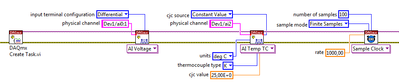
I want to use my PCI6014 DAQ card to measure 2-channel analog voltage input and 1 temperature Channel Analog input using thermocouple type k measurement of voltage or temperature isolation is OK, but I can't understand how to measure the voltage and the temperature at the same time... I want to use input differential...
Thank you in advance, all the tips
YSL
Create a task and add channels to the task, as follows:
Christian
-
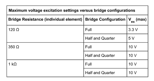
Confusion about the Source of excitement in the bridge SMU-4331 input module
Hello
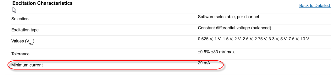
I had some confusion through the input of the bridge SMU-4331 sheet module.
In the features section of excitement, its current Minimum as 29mA says. What it means. It can only current greater than 29mA delivery!
I think this should me Maximum current specification.
If you look at the table below
350 ohm resistance, the current should be 10V/350 ohm = 28.5mA
but for 1 K ohm, current will me 10V/1Kohm = 10mA, which isn't normal, if you specify current minimum as 29mA.
any thoughts?
Kind regards
Mirash
Hello Mirash,
I'm glad I could help!
As for your other question, the SMU-4330/4331 are inherently peripheral ratiometric. This means that they are designed to detect the level of excitement and range of the ADC to the appropriate scale. In this way, we can compensate for permanent changes in the voltage. One of our engineers wrote a big article really nice area on the subject I would recommend that you take a look at: Sensors of Measuring Bridge-Based with the ratiometric approach
See you soon,.
-
Shaking with lines across the display screen
Hi, can someone please help?
Having used my laptop the other night, I closed it. A few hours later, I opened it again to use it, and although he had not been touched, both lines have one appeared on the screen.
We run about a quarter turn from the left, from top to bottom, and the other completely across the top.Also, the display keeps excitement up and down, shaking so I can't read it.
Anyone know what this problem could be? And if she needs to be repaired is it covered by the standard warranty?
Also there is no external damage and nothing has been done to the laptop - so I am very confused!
Help, please.
Problem may be defective.
How to tell if the repair is covered by warranty when you didn t wrote what model of laptop you have and how old is it? But if you have the Satellite C it must be fairly new, so it will certainly be covered by the standard warranty.Check the expiry date of guarantee under the http://www.toshiba-tro.de/unitdetails
-
protect high voltage of the PCI
Hello!
I intend to use an NI PCI-6040E coupled with BNC-2110 connector block by a cabel SH EP 68-68 to measure the power of a photodetector. I found that sometimes the photocell exceeds the input range of PCI card signal (~ 5 volts). I just measure with a voltmeter. Is there someone to help how I can protect these materials? I will use another material of control of input data? or is it possible to make a limitation by Labview software?
Thank you in advance,
FA
the correct answer depends on which line you connect your photo detector. Tea TREE is a few circutry protection of the entry on the device. you want to stay within the limits as you can read in the data sheet
You can use external devices to limit the voltage on the photodetector.
There is no way whatsoever that any software may limit an external voltage source.
-
How to measure voltage every minute
Hi all
Currently, I'm new to labview and I'm taking steps of timed voltage. Here's what I'm trying to do;
I'm using labview 2010 and I am currently taking readings of temperature and moisture in sync with each other. To measure the temperature, I'm using a cDaq mudule 9213, humiduty I am in using the voltage of the module 9234 and converting using the temperature and pressure of my moisture sensor.
Now what I want to do is take the voltage and temperature say every minute or 30 seconds, but my buffer fills based on the readings of voltage and gives me an error or the table accepts the values of what im assuming is the buffer, one by one, rather than enter the data of the current module.
My real question here is how to take measurements of voltage current every 30 seconds?
Thanks for any advice.
-
When I scroll in Firefox, a feint but remarkable line of distortion (directly in line with where my cursor is grabbing and dragging the scroll bar) appears horizontally across the page in multiple windows of Firefox. It is in any other application. Mac OS X 10.7, Lion on a Mac Mini Server, 2011. Suggestions or files I have to remove to do that, go away?
You are welcome
-
Re: Equium M50-216 - lines across the screen
Hi my Equium M50-216 has lines across the screen and low who go up and down the screen.
There is no picture it s just white.If I plug it into an external monitor I get a fine display on the monitor is so the screen is defective or something else?
I think that the inverter is ok because it of bright and not dull.See you soon
I agree with Luke.
If the image on the external monitor is ok then the graphics card should be ok.
If an FL inverter would be defective then everything would be visible, but just a little more dark and as behind a fogIn your case, it looks like a display problem
I think you should ask a technician for replacement laptop
-
Satellite L830 - horizontal line across the screen
All new Satellite L830 has a horizontal line across the screen.
What can be the cause and how can be fixed?
If the laptop is brand new it back as soon as possible and ask for replacement.
On this virtual path, it is not easy to say what the problem is here, but it may be related to faulty display, especially if you can see from the first moments when the laptop is turned on.Don't try anything. Request a new one. If you can not new, contact the nearest Toshiba service provider and ask for help. They need to exchange the defective part.

Maybe you are looking for
-
F2 BIOS SET-UP button stopped working on the Satellite A500-1GL
I recently bought a Satellite A500-1GLThe use of the F2 key at startup to access the BIOS worked fine until I changed the settings in BIOS to get a faster position for Windows 7, then after this change, that the F2 key gets me to the BIOS, the comput
-
Pavilion dv7-3150ez: enter BIOS
Im trying to get into the Bios on my HP laptop and when I do its asking me to enter the Admiistrator password? I have no idea what it is when his evil entered three times it says system off with the code 93847816 HELP!
-
iCloud 5.1 fails and can not reinstall after Win10 build 10586
Yesterday my laptop with Windown 10 Pro N has been updated to build 10586. Since then, iCloud connector is broken. No synchronization on Photos etc etc. So as usual, I tried the action known as: disconnection from iCloud, Uninstall. After uninstallin
-
Update Windows (vista OS) never finished the update and keeps looping back to step 3.
Windows Update was updated and the system was arrested by mistake. When the system is turned back on, the update process began in stage 3, goes to 50% then completed, he stops, stops, restarts and returns to step 3, States repeats the process over a
-
Loading the OS without usb DVD
Can I copy windows 7 recovery disc of the operating system on a flash drive to transfer to my computer hp mini 210-1032cl? I don't own a usb DVD and really don't want to spend on something I'll use only once. Thank you for your assistance expected.