DC 4276 bias introduced by Labview
I work with the meter of LCZ 4276, and I downloaded and installed the driver for it. However, I opened the example VI and it seems to work except it puts an error 'ERROR 1300' in Labview and on the instrument really it shows "ER 13".
I talked to my colleagues about it and it seems that there are some hypotheses of labview over the instrument. In the manual of 4276a (Section III, 3-14) (page 56 in pdf format), it is said that this error occurs if internal polarization DC voltage has been set via the HP IP but the instrument is not equipped with Option 1 (which is a DC Supply), or it occurs if the comparer enable code (E1) was sent through the HP - IB , but the instrument is not equipped with option 2 (which is a comparator/Manager interface).
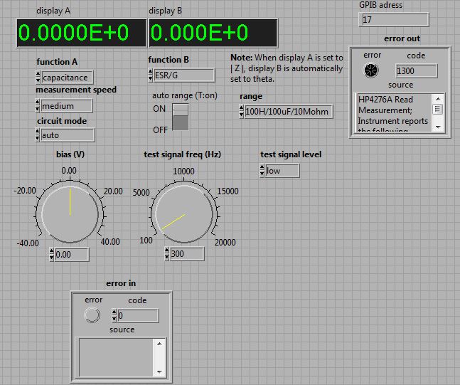
Well, this 4276a does not have the option. The switch on the instrument that turns DC polarization is off. However, as you can see from the picture showing my error, it is a DC bias in the VI himself.
So I ask myself, how I would you turn off the DC bias or LabView to stop running? I looked through the subVIs that make up this example.VI, and there is no code which entered the channel 'E1' for the activation code, so I don't think that the error occurs due to Option 2.
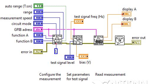
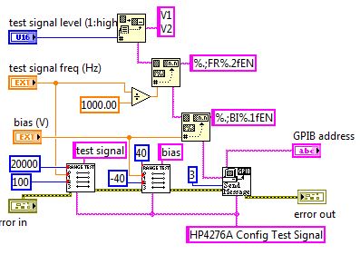
I have added the block diagram for the example.VI. In addition, I added the Subvi (ConfigTestSignal.VI) that contains the DC Bias input.
I would like to know what you think. Thank you!
Hello Erny123,
I have not read the manual, but I guess that BI is a string that specifies a configuration of bias, and indicates the end of the command. "%.1f" is a format specifier that inserts a value decimal floating point with a figure of precision (see this link for the syntax requirements when you use the Format function). Right at the top you can see that a similar format function is used to insert the test frequency in the chain of command using EN rather than BI and a slightly different digital format.
The example you are using was not written using the standard style of LabVIEW, it can be a little difficult to follow the entries and exits to go where. Try to click the icon own schema in the block diagram of example to rearrange things in a more logical way of left to right.
That makes this VI composed a string of commands to send to the device - you need to consult the manual to see what are the requirements of presentation, but I guess you can just delete the second format value function and wire the output of the first through sending message VI.
I wouldn't say you have to start from scratch every time, but yes, you will need to make some changes in this example so that it can work for you. I highly recommend that you go through one or more of the LabVIEW tutorials available online, it will save you a lot of time in the long run.
If you have an active support contract and your serial number of the software has been activated on your account of ni.com, you should have access to the basis of LabVIEW training online here:
OR Online Self-pace free-training
If you do not have access to that, there are a number of other Introduction to LabVIEW tutorials available on ni.com links on the right side of this page are a very good starting point for online tutorials:
LabVIEW academic training: how to learn NI LabVIEW
http://www.NI.com/academic/labview_training/
Kind regards
Tags: NI Software
Similar Questions
-
LabVIEW 2014 does support CDAQ 9136
I use LV 2014 SP1, I wanted to buy CDAQ 9136 Windows controller for one of my projects. I'd like to figure out if I can use the SP1 of 2014 LV with DAQmx15.1 in the program for this controller? User manual CDAQ 9136 does not say anything on the support of LV, just said that DAQmx 15.1 is supported.
When I tried to add a target CDAQ in SP1 LV2014 with DAQmx15.1, it does not show the CDAQ 9136. I won't use the real time of the CDAQ 9136 version, but I'm confused. Any help would be greatly appreciated.
Nanda,
I would like to clarify the compatibility for the NOR-9136. It is compatible with DAQmx, starting with DAQmx 15.1. In other words, it can be used as a normal cDAQ chassis in any version of LabVIEW with DAQmx 15.1 or later installed (within reasonable limits). However, compatibility in real-time with the cDAQ-9136 has not introduced before LabVIEW time real 2015 module, which is only compatible with LabVIEW 2015. Thus, to use the cDAQ-9136 as a real-time controller, you will need 2015-LabVIEW and the module time real LabVIEW 2015 or later. This note can be found in DAQmx 15.1 notes for supported devices.
-
Problem call Matlab external function under Labview 7.1
Hello
I have the problem when I want to call my m.file function in the script Matlab under Labview 7.1, that labview does not seem to be able to find this external Matlab function. I searched this forum, someone talked about setting search path in the tool-> option-> Matlab search path, but it seems that it does not exist in the version 7.1.
Is it possible to solve this problem in version 7.1 or update to the latest version, the only solution?
Thank you
Hello
I think you're confusing the LabVIEW MathScript nodes and the MATLAB® script. The MathScript node is introduced in LabVIEW 8.0 and the setting of path search that you speak to MathScript, reason why it does not exist in LabVIEW 7.1. Look at the example of differential equation Lorenz for the MATLAB script node. It shows how to set the path of research to be compared to the VI. The example is found in the node of script examples\scriptnode\MATLAB - Lorenz Diff Eq.vi.
MATLAB® is a registered trademark of The MathWorks, Inc.
Grant M.
Staff software engineer | LabVIEW Math & Signal Processing | National Instruments -
How to measure the frequency of a clock using meter in LabVIEW?
Hi guys,.
Someone knows how to measure the frequency of a signal introduced in LabVIEW (in the FPGA PXI-7813R), using a counter in LabVIEW?
Essentially, I want to use this counter as a kind of Logic Analyzer.
Thank you, Anoop
I don't know what you mean by "manual". It is all managed in a housing structure.

-
The Keithley 2612 is compatible with Labview 7.1?
Hello
I have a shiny new Keithley 2612 A two-channel sourcemeter and want to begin using this system of our laboratory. We are currently using LabView 7.1.
I found a driver for the 2612 has, but he says that it is only compatible with LabView 8 or later:
http://www.Keithley.com/base_download?dassetid=51950
Does anyone know of another driver, or another method that I could get this thing working in LabView 7.1?
Thank you very much
John
Download and publish it on the thread Downconvert .
Edit - this is a style of project pilot who introduced with LabVIEW 8. It might take a little longer.
-
Using LabVIEW with MSP430 LaunchPad?
I was introduced to LabVIEW this year in my class of only senior school ESD (technical design and development). This year, our class decided to compete in the first Tech Challenge, for the first time. I am very good with computers, so I took the task of being the only programmer. We did very good for our first year, placing 7th on 35 teams. (Mainly because the autonomous as in LabVIEW, I did on the bus ride to the competition) I fell in love with LabVIEW, especially because the NXT graph that accelerates programming programming process significantly. I am now hook on LabVIEW and want to do some of my own personal projects. I recently found the MSP430 LaunchPad that comes with both the MSP430G2211IPN14 and the MSP430G2231IPN14. I decided to buy two of them with one of their capacitive touch BoosterPack that also contains the MSP430G2452IN20. What I was wondering is it possible to read these microcontrollers data values and also program them in as the NXT LabVIEW?
Thanks in advance.
Although I've never seen this device, a little research on our website came with this resource http://zone.ni.com/devzone/cda/tut/p/id/11977 on this microprocessor programming in LabVIEW. I hope it's useful!
-
Hi I have a question that I really need to get fixed so I can get some reports. I called NOR and they are still trying to get back to me with a response as well. I hope someone here can have an answer. I'm using Labview SignalExpress 2011. Recently updated to 2010. In 2010, I could record the data and he would write in an excel file. In this excel file it would show groups decimated, a sample of each one second, then one other group which shows a sample every 50 seconds, then another group which shows a sample every 2500 seconds, and so on. It is perfect for creating graphics on 10 days of testing long that I do not need every second single for sample. Since I installed 2011, is no longer decimates the data for me. I get a single sheet with a tab that shows each sample excel. There is none made the decimation. I used the trial tiara to open one of the files and he showed groups of existing decimation; However when opened in excel, I do not get groups of decimation, I need.
The Rep NOR said the reason why it doesn't show groups of decimation is because when the graphical representation of data in labview, chosen 2010 any group of decimation was preferable to create the chart. In 2011, labview expects that the computer must be able to calculate all the samples. Which is fine but I'm not using labview to create graphics, nor do I want to spend over a grand on tiara to decimate my data. 2010 did, how can I do 2011? Thank you.
Chris
I thought about it. The Excel Add - In 3.3 CT introduced in Labview 2011 deleted this feature; or a hard to find the setting. I just went down to 2010's TDM Excel Addin 3.2 and the problem was solved. I can now open excel and get all the decimated data.
Chris
-
PID regulator takes advantage of the transfer function of the model sys
Hello
I need to find a controller for my system...
I have my system as transfer function model and I want to find the pid of the gains of this system by using its transfer function!
All block in labview 8.5 to do this step?
Concerning
Hello
Maybe this link will come close to the feature you're looking for:
Analytical design of PID VI
http://zone.NI.com/reference/en-XX/help/371894E-01/lvctrldsgn/cd_pid_design_pal/
This function was introduced in LabVIEW 8.5 in the Control Design and Simulation Module. There is a limitation, because this process analysis based on one or more transfer SISO (single Input Single Output) functions. The help article above comes from aid in 2010. Below, I've included the 8.5 reference:
-
problem by creating a virtual traditional NI-DAQ channel
Hello friends,
in fact I change computer daq to a machine, but for now I have problems when I try to create a virtual channel.
I see the jury on the devices and interfaces but when I fill in the parameters of the analog track exactly in step giving the ports, and the channel of material not appear anything and when I finished the configuration in the virtual channel properties appears invalid configuration and there I can't select anything in the hardware channels.
I don't know what is happening?
I installed labview 2009 Windows 7 with MAX 5.0 and NI DAQ 9.4
Please help me or ideas on the...
Thank you...
You change os or change at DAQmx. Traditional DAQ has been made obsolete when DAQmx was introduced with LabVIEW 7. If your card is one of the old cards that didn't is not supported by DAQmx, then Yes, you would also have to replace one if you stayed with windows 7.
-
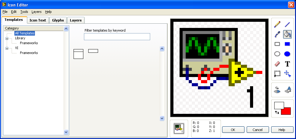
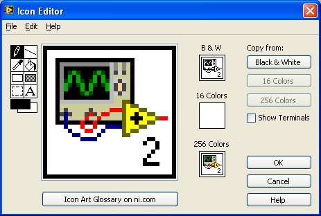
LabVIEW2009: How to replace the new Icon Editor with old?
Ladies and gentlemen,
I really don't like the new icon introduced in LabVIEW 2009 Editor:
It was tried to "Photoshop shipped" with a lot of features:
But I don't like it really, because:
-It has opened EVERY time on the RIGHT monitor (I have three monitors and main monitor in the middle)
-It takes a lot of time to launch (former editor of icon start momentally)
d ' usability point of view - it was wrong to place tools on the right side. Often, they are on the left side (and only in the old icons, but also in imageprocessing Editor software like Adobe Photoshop). Also front of interface design user Panel... hmmm... This can be better...
-some bugs or modified features (for example - KING to select, then press the
button - nothing happened)etc...
Is it possible to replace it with an old man:
Ideal solution will be - switch just between two editors (some features introduced are not so bad).
Thanks in advance,
Andrey.
Go to
\Resource\Plugins and rename lv_icon.vi. It is a plugin that is called when you call icon editor, and if it isn't there, LV is the Editor (at least for now. I don't know how many versions to come, they will keep the code). Note that the editor is open source, so you can enter and change what you want (or save you time and use the changes others did, as the thread of PJM here. You can also watch other discussions in this group).
-
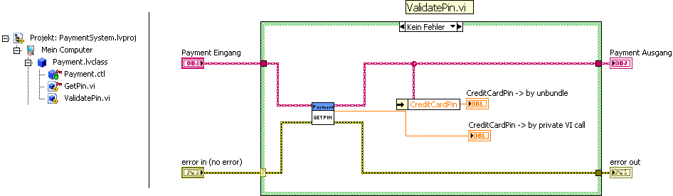
LV OOP using accessor (subVIs) or operation bundle/unbundle methods?
Hello
When should I use the (private) (subVIs) accessor methods and when the bundle/unbundle the operation to access the data of the class? What is the reason that the operation bundle/unbundle is introduced in LabVIEW OOP? I need some rules for a codification of the directive.
Thank you
Thanks for your advice. I wanted to understand the differences between a private access vi and unbundle operation as in the picture.
I found a few more explanations on the website: http://www.ni.com/white-paper/3574/en
-> ' Methods 'Read' and 'write' for each data value in a class is a recognized process as being bulky. " LabVIEW 8.5 introduced the ability to create the screw accessor in a dialog Wizard and LV2009 added to other options in this dialog box.
We were concerned about the performance overhead to a Subvi call instead of unbundling just data. We found that our general fees current compiler for the Subvi call is insignificant (measured between 6 and 10 microseconds on average PC). A bundle/unbundle directly on the appellant VI compared to a Subvi is almost the same amount of time. We have a problem with copies of data for unbundled components because a large part of the LabVIEW inplaceness algorithm does not work beyond the limits of the Subvi. To work around the problem, you can also choose to avoid the accessor methods for methods that perform work in the Subvi to avoid returning the Subvi elements, thus avoiding copies of data. This choice is often better OO design anyway, because it avoids exposing the implementation private to a class as part of its public API. In future versions, I bet that this feature of subVIs will become possible, which will eliminate the overhead entirely.
We feel in the long run it is better to improve the experience of the editor and the efficiency of the compiler for these screws rather than introduce data public/protected/community. »
-
I know that express VI is generally frowned upon here. My question is why?
Is it because people think that the programmer should be able to do (manually) that made the express VI?
Or is it because express VI generally perform not very well?
The reason I ask is because I know how to use the stuff of data acquisition, but I always use express VI when I need to send a large amount of data at once.
For example... If I need to read or write simple lines or ports I'll do it manually.
If I need to empty a buffer of 1 K on a map of FIFO memory, I will use an express VI.
Other people will tell you that their reasons for not using them. When screw Express was introduced experienced LabVIEW programmers seen with a lot of grief. In fact, there is a famous video which was taken at one of the meetings OR requiring experienced programmers to LabVIEW to screw Express name 10 they could not. Not because they didn't know LabVIEW, but because they stayed away from them. My personal opinion is that NEITHER basically was trying to take a cookie-cutter programming approach. On the one hand, they wanted to say that LabVIEW is a complete programming language. And on the other hand they wanted to say that the non-programmers could use it. That is why the live Express. When they came out first, they were terrible in terms of complexity and overhead. That they got the best. For example, the time Delay VI is very useful. So the elapsed time VI. So is the Fialog file.
Another reason why screw Express are frowned upward it is because data acquisition that they use dynamic data type which is a bit next to type of useless data. I'm sure that OR it will be just like being the greatest thing since sliced bread, but I'll take the data type of waveform on the dynamic data type of any day of the week.
-
Violation of compilation-Timing error FPGA
Hi all
I've been LV around for years, but I am a complete newbie when it comes to FPGA. I'm working on programming for a 9651 (SOM) using the Dev kit. I'm starting by small steps, but already tripped. I have a simple VI which retrieves a value from a FIFO and passes it réécrirait a different FIFO. When compiling, it gives an error of timing violation, and I don't know how to study. The VI is attached.
If background for the curious... I'm working on the side of our application to signal processing. I'm passing data from a prerecorded TDMS file to a FIFO. I want to send the FPGA, treat it and send it back. Eventually, it will come of I/O, but for now, I just want to work on the processing of the signal. Before starting work, I thought I'd just make sure I can transfer data to the bottom and back. Once I get this job, I'll start to developing processing screw for between the two.
Thank you!
Hi thutch79,
You can specify the version of LabVIEW you use and implementing CLIP half bridge that you use for the IO DevKit?
It was a timing violation introduced between LabVIEW 2014 and 2015, given the way the compiler Xilinx handled VHDL which takes in charge the second port Ethernet on SOM. If you use a CLIP half bridge that has been generated before 2015 LabVIEW (as the example of the expedition which I think begins with a CLIP called "DevKit"), then you can get a timing error. There should be a second sample CLIP called DevKit2, I think, which was regenerated with compatibility for 2015 of LabVIEW and later versions.
This problem has been discussed here: https://decibel.ni.com/content/thread/42711
You can check your half-bridge CLIP in the project by ensuring that you have selected the version called DevKit2 if you have a version of LabVIEW FPGA which is 2015 or newer.
Kind regards
-
Scripts (connect a Terminal to a flat sequence Structure)
(script)
Is it possible to connect a terminal to a flat Structure of the sequence? (in my case, with a single frame)
(with the "Connect Wire" method)
Ouadji wrote:
but the main question is... Why the flat sequence structure does not inherit from node?
Why the developers chose this?
What is the main idea of this choice?Flat sequence Structure introduced in LabVIEW 7.0, provides a semantic schema object that no other object has. It is a structure of multi-frame (like a case structure or a stacked sequence), but it is the only structure where data can be wired between frames through normal tunnels. It is the only structure which may have tunnels in places other than its external borders. It is the only structure that can have subdiagrams of different sizes in different positions. It also introduces scenarios of strange wiring that you won't find elsewhere:
At the same time that the flat Structure of the sequence was introduced, there was enough of these bizarre scenarios with scripts (which was an internal feature NOR at the time), it was easier on the developer to make his own script class to try to find a way to support it under an existing class. We had no idea that script would become a public service someday, so the burden was relatively low and limited within the walls of NOR. Looking back, there have been enough problems with the FlatSequence class in the script than most of us agree that it would be better to have it in class Node (or more precisely, the class MultiFrameStructure) from the beginning.
-
What should I do first a Bachelor's degree in law and make mnu then, so that I can make the mnu to the library?
Have you seen the tutorial on the Development of instrument Drivers? The pilot project-style introduced with LabVIEW 8.0 and has some advantages. You avoid collisions of names VI and the structure is adapted to the source control. The old llb puts everything in a single file that is not appropriate for the individual vis source code control. A Bachelor's degree in law also has the serious disadvantage if a single VI it is corrupt, the whole llb is unreadable.
Assuming you are using 8.x, you can watch the pilot 34401 expedition to France to see the structure of a pilot project-style.
The distribution would be a zip file, just as does NEITHER. As long as the driver is installed in the instr.lib folder (where you would also in), it would be not all broken links.
Maybe you are looking for
-
I had a problem with my HP Chromebook intermittently keys work only not - y, m, n, etc. They would work, then not work, and it was very frustrating esp to log in b/c I couldn't get my typed password. I thought that I would need a new keyboard, but m
-
. Help copying images - "cannot create or replace family photos. Access is denied.
When I try to copy pictures from my computer to a Lexar removable I get this message. "Cannot create or replace family photos. Access is denied. Make sure that the disk is not full or write protected and this file is not currently in use. Please help
-
How can I get the viewer photo and fax for windows on windows 7
my computer does not have windows fax and picture viewer but has the windows photo viewer. Unfortunately the windows photo viewer is not moving images. I need help Thank you
-
Corrupt Vista - > Downgrade to XP - > Windows 7 upgrade
My desktop PC with Vista Ultimate 64-bit OEM version won't start. It loads up to: \windows\system32\drivers\crcdisk.sys. Message error "BootMGR image is damaged. The system cannot start. "I tried a Vista startup disk, but it has not yet loaded. Optio
-
VGA graphics card cannot start (Code 10) on Alienware M14x
Recently, I deleted from my hard drive and reinstalled Windows 7 and now all my games (COD Black Ops, FSX, etc.) and other programs such as Google Earth are Mid-use freezing and I have to force to leave them via the Task Manager. There is a sign of w