Detection of peak
Hello
I'm doing a heart rate using LabVIEW and arduino monitor. The base material using a LED and a photoelectric cell. You place your finger on the LED, with the photoelectric cell above, and the cell detects changes in the amount of light in your finger whenever your heart beats.
My design works very well and is able to detect changes in light. However, I can't calculate these changes and convert the data to a heart rate. One of the problems is the detection of crete, in which you set a threshold value and the detector seeks amplitudes above or below this value. The problem is the amount of light which crosses his finger varies greatly, so even if a pulse is clearly observable, you cannot set a value for the threshold to seek.
I tried to solve this problem by making the threshold vary, whereas it would be slightly lower than the average, but my code still fails to detect a pulse. Does anyone have an idea how I could solve this problem, or if there is a better method than using the default tip detect?
I have attached a copy of my code and would be very grateful if someone could help. Thank you very much!
Tags: NI Software
Similar Questions
-
Detect the PEAK, mount and average
I use a loop in LabVIEW 8.5 to capture the signals emitted continuously by a card, peak detector.VI is used to detect the signal peaks, then fit.VI nonlinear curve is used to climb the summits, signal now capture, detection of peaks, mount and display pics are all works very well permanently, but there are still some problems annoying me.
1. the received signals is not very stable, so editing results expected on average for 100 times, then how can I averaged the results of fitting on the condition that the capture of signal is not interrupted, this is the time loop does not stop, when the average is made this time, average is reset for the next 100 fitting results can be average again?
2. There is another way, that's 100 results of fitting is automatically saved to excel, then the results is an average manually in excel, then how to store results like this: the first 100 results of connection are stored in an excel file and the next 100 results for other excel connector or they are stored in an excell , but in different columns? Of course the thses are subject to the capture of signal is not interrupted.
3. There is a threshold for the detector.VI peak, but the captured signals entry isn't very stable, so the number of peaks detected is not the same every time, like this time, the number of vertices is 40, next will be 39, this will affect the results of fitting slightly, then how do to detect the same number of vertices every time such as the number is 40 each time?Any advice will be appreciated!
Maybe the pic attached detect.vi 'test' can help you. "medium signal.vi" is a sub VI on average the signal in a way online.
There are three methods using the input signal:
1. no average.
2. average exponential.
3. linear average.
Your problem is when the input signal is damaged by some noise, and you want the input signal before the detection of peaks on average. I use white noise to simulate a noisy environment.
By default, the average mode is 'Linear', and the number of averages is 50. The more averages, the best on the result, but more time to update.
Swith mode between 'Linear' and 'No way' to compare the difference before average and average.
Average exponential is not appropriate in your case.
Let me know if it works for you.
-
detection of peak with two thresholds
Dear colleagues!
Excuse me, but I need example or any help for the detection of peaks with two thresholds. Namely two adjustable thresholds with detector standard Ridge for the creation of a detection bandwidth or range.
Detector of crete have only one threshold of... But why only one...

-
Detection of peak at the same time
Hello
I have two waves A and B with 10000 sampling point.
Now, I want to find Max and Min waveform peak value has and correspond to what I want to know the respective value of the B wave.
So end of thw Finally I have the Max value of A and this is the respective value of B.
For this so I want to know the basic idea.
Thank you
After samples were taken by the waves. Use "Table Max and Min" on a range, or edge detection
Then connect the clues of the max and min for "Index Array" of table B.
-
How to detect the peak frequencies in the frequency domain?
Hello
I built a small test consisting of two sine waves of varying frequencies, program it is and subsequently FFT is performed on it to find the frequencies of two peaks. I tried to display the values of these two frequencies somehow, but I can't find a way.
I searched the forum before asking the question, many of them suggested using extract more Information VI tone I tried and could not get any results.
I have attached to my account. Please take a look. If you know all the discussions on the forum directly related to my problem, please just cite it.
Thank you
LD
Don't wire the tone of several extracts the wire coming from the Express VI of Sprectral. You need to run on the thread after that the two signals are summed.
-
Detection of peaks software using and adding the entire maximum amplitudes it finds my chart
Hello
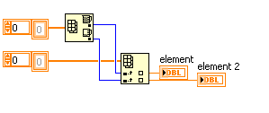
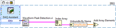
I'm trying to take my maximum amplitudes and multiply them by a constant I determine and then each amplitude added in a 32-bit integer. A usage example detects the acceleration of 5 shots, multiplying by a constant max amplitudes, add them all together and a 'score' of output for this people shots.
A simple version of my code is attached. The output of amplitdue of Ridge detection is where I have a problem because it is only display a table and I want to add all the values in a single 32-bit integer.
Thanks for the comments, it is greatly appreciated!
Zack
Zack,
Try to use an array of Index followed by a Unbundle by name to get a digital output. Then, you can use add items table to summarize the.
I would like to know if that's what you're looking for!
Katie
-
Detection of peaks of waveform data
Hi people.
It is probably obvious, but I can't understand it. In the attached VI sine wave detector summits are determined from a simulated signal. I want to be able to do the same thing with a waveform data (DBL), but it won't let me. How can I extract the signal of the LDM to feed the rest and make the waveform work VI right Ridge detector?
Thank you
Select this option.
Use of DDT, found in the range of Signal handling, to change the dynamic thread in a waveform.
Bob Schor
-
Extract and save all the channels of the PXI-5105 with 4 M of edge detection... Help!
Dear collegaues!
Please help me to improve my request, exhibit attached and sorry for my English.
So my task is to extract and save all the channels (eight) of the PXI-5105 with 4 M of detection of peaks and sample rate 4 M with loop 1 sec...
Entered all my channels are wiring detectors NaI with 0, 5... 1 microsec pulse (really) width and 0 kHz at not more than 40 kHz freq.
Why I chose the registration of 4 M and the sampling frequency of 4 M namely? Answer is that I tested previously PXI-5105 40 kHz generator and pulse width 0.5 microsec. It works great and detection of peaks indicate 40000 pulses/s for me. If I set lower than 4M record and sample rate of 4 M, it is without work. In my honest opinion record 4 M and the frequency of sampling of 4 M are parameters very min.
In the detection of peaks time present only 6 working channels... When I connected to diagram more 6 "detector.vi peak" - I see the error "...". out of memory... ».
Advise me please, what needs to be done to it, it's all working well.
-
detection of crete during the acquisition
I am gaining of daqmx permanently a signal (single channel dbl table or waveform).
The signal is a waveform of the triangle.
I need take time between the ridge and the Valley for each pic.
I try with peak detection but does not work, the acquired signal are not windowed period.
Also, I need to record the results of the evaluation (amplitude /valley, Peak and Valley Ridge at a time) for each line
Can someone help me?
Thank you
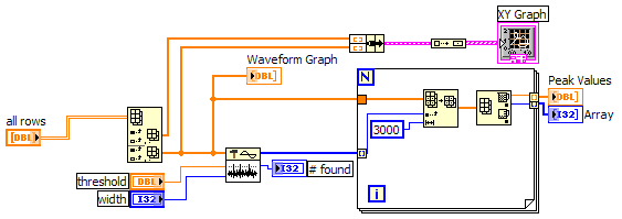
It's a start, now if you feed the data from that output in a "waveform peak detection VI. You will need to play with the threshold and the width for this VI entries in order to determine how detection works. You can also change the entry all about choose if you are detecting the peaks and valleys.
One thing to remember is that the threshold value is the minimum of a peak or maximum value of a valley.
You must also be a sort of timetable for the loop (an expectation of 100 ms) or set the timeout/samples by channelvalues if you want to get more then 10 to 20 samples per waveform.
-
Input analog continuous USB DAQ find amplitude peak to peak
I need to know if there is a way to use the crest detector when you do an analog voltage input. I use c# VS2005 and 8.6.
Hi jsheridan,
Have you looked at the Ridge detector example that comes with Measurement Studio? The c# example can be found here: C:\Documents and Settings\All Users\Documents\National Instruments\MStudioVS2005\DotNET\Examples\Analysis\PeakDetector\cs (assuming that you have installed on your C drive :).
The example generates a waveform and uses the PeakDetector class to detect the peaks. You can take this example and modify it to support what you are doing, or just put some functions in your code. The detector function takes an array and outputs tables of places, the amplitudes and the second derivatives of the peaks and valleys in the array passed to it. If you prefer to use all the time, you could just do a ridge detection after each reading some or all few seconds so that you make a lot of unnecessary calculations.
-
Hello
Something seemingly simple I can't go to work...
Please see the attached VI which contains a constant matrix (which represents a typical set of acquired data points) on which I perform a detection of peak/Valley.
I would like to find the valley (s), but any "width" is used, it never finds valleys.Any ideas as to what this may be or suggestions on how else to determine the location of the Valley?
Thanks a lot for your help!
Jack
Hello
You must connect a value for the 'threshold '. This entry indicates the VI to ignore the valleys below the acceptable threshold. As it is has no valleys in your dataset below 0, you detect not everything if you don't the wiring in this entry.
If you set the threshold for '800' value allows you to detect a valley. If you set the threshold for '1200' value, you detect the three valleys.
I hope this helps.
Kind regards
Dave.
-
Hi all
I am a new user of LabVIEW and I'm going to ask you about a problem that certainly many of you will find quite annoying.
I develop software for a test machine management that uses an another bend, a tachometer that generates a signal of rectangular analog output in volts, 0V to 8V. Like many I thi signal in a waveform graph.
My goal is to be able to count the number of cycles of the machine and power count the tension peaks and subsequently be able to work on the machine with respect to the number of rounds to make. the ultimate goal is to be able to tell the machine how many rounds/cycles to do and the voltage applied to the load cell.
Would you be able to give me some advice on this subject? Especially about count and store the number of revolutions.
If necessary, I could send a screenshot of the program.
I tried to use a crest of the threshold detector but I'm still inexperienced, it's why I ask for your help.
can someone help me?
Thanks in advance.
Greetings
LV
Look at the detection of peaks VI and examples (help-> find examples).
It should be fairly easy to understand and implement

-
There are mainly 2 peaks of the curve as the subplot in attachment 1. It should detect the point of division as the Red cycle.
I tried to detect where the second derivative change of polarity to locate the point.
But sometimes there sub such peak in case 1, so will miss it.
The duration of each peak can also change as in case 2, so I give up to locate the peak in the window of time constraint.
I also tried the detection of peak in LV function, but some cases also does not fit.
But in any case, I can identify the point of my eye.
Is there a good way to do it, can give all the details, thank you.
Here's a possible algorithm:
1 calculate the dydt for data.
2. apply a threshold for dydt values that are of interest. Keep the index numbers of each element whose absolute value is greater than the threshold. It would be to restrict your search to the regions where the value increases or decreases of parachute.
3. look at the "window" of data around each point of interest. You will need to decide how many data points compose window.
4. go to the window where there is both a positive dydt negative dydt in reasonably close. One way would be to use array max/min function and do a subraction.I think it will work if you play with the window sizes and threshold.
-
Detect the shift in two consecutive low contrast images
Hello
To determine how fast a sample of ice sliding USB camera (rate of about of 30 mm/min) I head to align an image every 5 ~ 10 sec and then compare the two images. I'm fighting to get a robust method to determine the displacement. The main displacement will be that in a sense however ice may move a few pixel widths in the other direction as it slides in front of the camera.
Currently I am comparing the two images taking a large (400 x 800 pixels) KING of the second picture, then taking the pixel values average of all the columns in the two images that then allows me to subtract 1 d arrays that result and find the position where the difference is minimal.
This works very well for the "perfect" images but no longer reliable with less then perfect images.
Because the images are samples of ice with very little "features" (not counting the odd are bubbles) and low contrast, I feel that I have to rely on profiles in levels of medium gray rather then a 'function' follow-up or detect an edge etc..The berries average grayscale of the King plotted in the graph to see the clear peaks and valleys, so another method would be to match the data but I don't know how to do it again.
Any suggestions on how I can better determine the displacement between the images? The method should relatively quickly because it must be in 'real time', i.e. within seconds.
Thanks as always for all of your help.
Jack
Hi again
Advice of Follwing Mike subtract images I've played around with this feature and have now the principle works well.
In case someone else I would try something similar please see attached the VI and two images of the example that I used to experience.Well yet, which doesn't seem to work, it's the method of detection of peak/Valley. Any width I put may not find the Valley... suggestions welcome!
Have a great day.
Jack
-
detection of crest of a noisy signal in offline mode
LabView dear experts...!
I'm trying to find the vertices in my Signal in offline mode. I would like to know the amplitude, location of the summits and manipulate. But the signal noise and if I try to feed them in this signal to a ridge detector it gives results falsely as taking small noise spikes. I want to get the great peaks (3 peaks in the data).
Please help me to detect these peaks.
When I used a detector.vi of the art for a simulated noise less data works very well. I'm using LabVIEW 7.1.
Waiting for your response.
This will give you maximum values without filtering. You get both with a bit more coding.
Maybe you are looking for
-
drive hard plenty do delete the caches and download the file
Hello I have a mac book pro running os x 10.10.5 yosemite and I am receiving message from hard disk is almost full. I deleted all caches and download files as well as any unused applications. It is not really that much on the computer so I'm a little
-
Hola, dan of you voy an estar en Miami y queria saber so mi Ipad Mini 2 entered the Center program a cambio y? Esta casi en terms perfectas nueva y.
-
Equium P300-19O - how to install the latest Intel graphics driver
same problem as this guy (http://forums.computers.toshiba-europe.com/forums/thread.jspa?threadID=36626&tstart=0) never tried to display drivers from intel and other computers laptops, but none will install via the main executable file or Device Manag
-
I was able to successfully install SQL Server Express 2008, but try to install the database with tools can produce an error. The error notice States that PowerShell must be installed and installation attempts that result in an error 0 x 80070422. HP
-
I use a Dell USB Optical Mouse, M/N M-UVDEL1, with my Dimension 4700. The mouse does not seem to be working properly. I can't find a CD for the mouse supplied with the system, and when I check the Dell site for drivers in the section of the mouse and