detection of crest of a noisy signal in offline mode
LabView dear experts...!
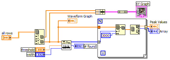
I'm trying to find the vertices in my Signal in offline mode. I would like to know the amplitude, location of the summits and manipulate. But the signal noise and if I try to feed them in this signal to a ridge detector it gives results falsely as taking small noise spikes. I want to get the great peaks (3 peaks in the data).
Please help me to detect these peaks.
When I used a detector.vi of the art for a simulated noise less data works very well. I'm using LabVIEW 7.1.
Waiting for your response.
This will give you maximum values without filtering. You get both with a bit more coding.
Tags: NI Software
Similar Questions
-
Hi all
That is the most effective method to differentiate a noisy signal of normal. The application receives signals and it should be able to determine if the signal is disturbed or not pragmatic. There also a value of threshold for spikes in noise that it must consider.
Thanks for your time in advance.
Concerning
IB...
I agree that the answer depends on what your signal looks like, but it wouldn't be difficult to determine if a signal is noisy. If your signal of interest is sinusoidal, you could do a FFT, then threshold levels other than your target, as a basis for comparison of noise signal. It is quite effective. If you have something that changes a little, like audio or data, here again, you might look at the spectrum, but look outside a frequency band and not only a single frequency. If you have a reference signal, you could subtract the received signal reference signal and the result would be your noise and you could measure it. This all happens to determine the quality of the signal, using filtering will help you clean it up, but not tell you how noisy, it is first of all.
Hope that helps.
Chris
-
Detect the frequency of an analog signal crossing of myRIo AudioIn analog channels
I'm working on a robot firefighting that runs using myRio. I have a small microphone plugged into the port of "AudioIn' of the myRIO, and the robot has to detect a certain frequency (2.8 or 3.5 KHz) to start navigating. The AnalogIn express VI gives me amplitudes of raw tension of type 'Double' but the 'tone Measurment' vi I wanted to use takes in a data type of "Signal". I tried to convert raw data into dynamic data and feeding it, but did not work. A problem is that I can't control the sampling frequency of the express VI AnalogIn (LabView 2013), I appreciate any suggestions on how to do it.
If you install the myRIO 2014 broadband module you can use the Audio input Express VI to sample between 1 and 30 kHz.
You will need to follow the instructions in the myRIO 2014 LabVIEW Toolkit Readme in the section titled the switching between the default and personalities FPGA high speed.
There is also a thread on the MakerHub of LabVIEW where the Toolbox broadband has been used to generate sound , so it might be a good resource to be part of the path.
If you use NEITHER-DAQ hardware, you can get access to the DAQmx driver but myRIO cannot use the DAQmx driver sample data.
Edit: You can also get more help specific myRIO by moving the post on the discussion forum academic hardware products (ELVIS, myDAQ, myRIO) .
-
Acquisition of time between peaks (noisy signal)
Hello Experts,
I'm new to labview and I worked on a VI on the acquisition of the duration between 2 peaks (real time). The source of the signal is human ECG/EKG (cardiac signal - PQRS). He has a huge spike and other smaller in each beat in torque, and the signal is disturbed. Now, what I try to do is just to get the duration between these peaks in real time (so it changes every time or it could be the average of several peaks).
If all goes well, I'm not confuse anyone of you.
I have spent a lot of time trying, but can not really understand how to use some of the functions available.
If possible, someone of you can show a simple example of how this could be done? (using sinosoid signal - noise - like source would be enough).
crossing my fingers!
Thank you in advance!
-
Using an 53131A, how do I detect the condition of no input signal?
Hello
I use an Agilent 53131 A frequency counter to measure the frequency of the oscillator. I need to be able to use the frequency counter to read the frequency when the oscillator is oscillating and indicate when the oscillator is bad (no signal present on the 53131A of entry). Does anyone have any suggestions on the type of command I should use?
FETCH?
READ?
MEAS?The problem I have is in the trigger. When the oscillator is bad, the counter hangs up because she continues to wait for a trigger that will never come.
Thanks for any help
In fact you have right to the solution yourself. You need to revise your release scheme or you can use the absence of trigger as your indication.
For example: you know that the measure will have x seconds to complete if the signal is present. If you need to determine whether the measure is right here. Simple if you use GPIB-
(1) set the property of VISA TMO to be as long as you wait for the measure.
(2) enable SRQ on operation completes in the meter. (ATTENTION: make sure that no other instrument allows to block Service Requestby the meter setting as low as possible address)
(3) when you send the boot command, you can query the status of the SRQ with the "wait for SRQ.vi" If no signal is present, then the wait fo SRQ will return with a time-out error.
(4) clear the error since you know what caused it and send a clear command (* CLR) at the counter to return to the idle state.
Alternatively, if the signal is present, the meter will trigger SRQ when the measurement is finished and you can then extract the memory reading.
-
Toshiba 32TL933G: No Audio signal in PC mode
Hello
I connected my laptop VGA to entry-level PC TV and the Audio output of the laptop to TV Audio IN.
No Audio in PC-Modus!Is it possible to go from Audio IN to the PC Input?
Now I have a video in PC * GOLD * Sound in EXT2, not together.
IF not, I will return itNevertheless a beautiful Asian.
RudolfThe fact is that VGA port does not provide the audio but video signal only.
So if you a TV connected to the computer laptop s port VGA, audio signal would not be provided.
You need connect the TV with an extra audio cable in order to get the sound.The laptop must be connected to the TV s L R taken audio using an audio cable additional of Y. So that you can connect to s portable headphone plug to two L R audio ports that are available on the back of TV s
-
DEADLOCK DETECTED - DELETE statement - how/why he expects in SHARING mode?
Hello
I wonder if anyone can advise here. The environment is:
Microsoft Windows 2003 Server
Standard Oracle 10.2.0.4 Edition
We had a deadlock detected in our application on a customer site - I enclose the corresponding part of the trace file below. While we think we have found the reason for the deadlock (looks like it is due to a foreign key in cascade), I'm confused as the lock mode that is requested.
Here is the track information:
It seems to me like session * 481 * trying to do a deletion when the block is raised:Deadlock graph: ---------Blocker(s)-------- ---------Waiter(s)--------- Resource Name process session holds waits process session holds waits TX-00120012-00003b59 28 475 X 29 481 S TX-000a0029-0003508b 29 481 X 28 475 X session 475: DID 0001-001C-000F96B0 session 481: DID 0001-001D-00000079 session 481: DID 0001-001D-00000079 session 475: DID 0001-001C-000F96B0 Rows waited on: Session 481: no row Session 475: obj - rowid = 00014625 - AAAUYlAAIAAAAawAAo (dictionary objn - 83493, file - 8, block - 1712, slot - 40) Information on the OTHER waiting sessions: Session 481: pid=29 serial=18261 audsid=202192707 user: 51/info O/S info: user: SYSTEM, term: our_term, ospid: 5244:940, machine: our_machine program: our_exe.exe client info: GUI application name: app, hash value=3864155245 action name: our_action, hash value=3631189430 Current SQL Statement: DELETE FROM TABLE_1 T WHERE T.T_ID = :B1 End of information on OTHER waiting sessions. Current SQL statement for this session: UPDATE TABLE_1 T SET T.STATUS_ID = :B2 WHERE T.T_ID = :B1
and ask which mode (dynamique31) S .DELETE FROM TABLE_1 T WHERE T.T_ID = :B1
(also the 'no line' for lines didn't wait)---------Blocker(s)-------- ---------Waiter(s)--------- Resource Name process session holds waits process session holds waits TX-00120012-00003b59 28 475 X 29 481 S
I thought it would be in mode (e) X (clusive) (for the line being deleted). Actually Yes, I set up a test of fast and simple locking and mode (e) X (is) expected the final delete .Session 481: no row
So, am I misinterpreted the tracing information, or is the DELETE statement requesting the lock in mode S (Hare)? If this is the case, I'd appreciate a quick explanation of how/why it's...
Kind regards
ADOSI think we have almost the same reason to wait in S mode as in [single key application | http://books.google.pl/books?id=14OmJzfCfXMC&dq=oracle+wait+interface+practical+guide&q=unique+key+enforcement].
If two sessions want to insert the same key value, the other must wait, because the outcome depends on a commit / rollback of the first session. In the case of validation, session 2 must generate an error in case of cancellation, it must insert his record.In the test provided by ADOS, at session 1 there is an insert in session 2 - delete. The result of the delete operation depends, once again, commit or rollback in the first session. In the case of validation, it must remove, and cancellations, there is nothing to remove.
If the insert in session 1 has been replaced by the Update, there is no S lock but 'normal' eXclusive
Bartek
-
Photosmart C410 will signal network offline / busy
My operating system is 10.6 with a Macbook Pro using a Verizon router. As I already posted the message I received was off-line and now it is showing this printer is busy, although nothing is being printed.
We will restore the print system:
-Sys Prefs, Print & Fax
-Right (control) click inside the box that lists your printers and select Reset Printing System.
WARNING - This will remove ALL your printers!
-Select the sign + to add again. Search for the printer, select it, and wait until the button 'Add' becomes available. Until it clicks. -
Hi all
IRB is possible to send a packet on the network with a wnap320 access point to restart.
I like to use network monitoring tool spiceworks to detect when wireless radios / SSID is switched to offline mode and set to true, restart the ap to get them online automatically.
Concerning
Robert Fernando
To restart wnap320
using
PuTTYnew PuTTY config entry
IP address of the access point
type: sshWhen ssh session begins
type at the prompt1: login name AP
2: password of the PT
3: reboot commandTypical output
Ph1 is the name of the access pointConnect as: y
[email protected] password:
PH1 #reboot -
P70 Pro SAT - signal strength dropped suddenly constantly
I recently bought the Satellite P70 Pro (2 weeks ago). It has Intel Pro Wireless 2200BG adapter. During the first week, I was able to detect approximately 6 wireless LANs near my apartment and my own WLAN has always been the power of the signal full (I use a Belkin Wireless Access Point).
I updated my Windows XP with updates of recommended security and after reboot, my laptop only barely detect my WLAN with very low signal strength at best, and I can't see all other WLANS that I used to work with the very good signal strength.
I do not understand why this has happened - I tried tto updated drivers Intel cards with the latest version (9.0.3.9) and also to restore my system to the date I bought it (IE restore to basically its state before buying). None of these actions has changed the fact that he basically can't pick up my WLAN more unless I'm ontop of it.
I think return the laptop and get the card replaced Intel because it seems defective.
If anyone has any ideas they would be greatly appreciated.
Thank you very much
Peter.Hello
I've read many users with different laptops, but with the same WiFi card have similar problems. Unfortunately have no explanation. I know that you can use the Agere or Toshiba WLAN card.
In my opinion, this card doesn't work properly with some access points or there is a problem with communication between them. I have the same card (Satellite M40) and WLAN Netgear access point. Since the first day, it works perfectly and without any update driver.
If you have time here to edge wireless you can find a lot of interesting topics on the similar theme.
Good luck!
-
MyRIO FPGA read framework signals SENT
Hello community,
I now have a myRIO with Labview 2013. I try to read a digital signal to a sensor on the port DIO0 (C-Port). It works very well. The problem is that I don't know how to find the start (the SYNC nibble) of the frame SENT - and how it works with the ticks of the clock / time clock of the FPGA (40 Mhz) system. I do not understand the meaning of the clock. ticks of the clock.
The next problem is to measure the time between a front down to falling edge. In fact I can detect every falling edge of the signal SENT but I cannot measure the actual time between them. How can I measure the real time based on the system FPGA clock time? The nibble of SYNCHRONIZATION were all 56 time graduations. But how long are 56 ticks?
Best regards
Basti
Hello, Alexander.
Thank you. It works very well.
Now my problems are solved. The main problem was to build something that is capable of converting 56 ticks of the SYNC signal SENT for correct ticks of the sampled signal. The two frequencies, the Signal SENT (333kHz) and the sampled signal (40 Mhz) are different, so I divided the frequency of the signal sampled frequency of the Signal SENT - (factor of about 120). Now I can convert 56 ticks to correct the number of ticks of the sampled signal and I can find the SYNC - Puls in FEEL. The result of 56 times the factor of 120 ticks is 6720 ticks. So, I convert ticks to the correct frequency.
Thank you very much for your help!
Best regards
Sebastian
-
SingleToneInformation detect nearly 0 amplitude to 0 hz
Hello
I use the 4071 DMM AND measure some AC signals. Sometimes I'm also trying to detect the absence of an alternating signal n (stable switch). My automation is all c#, I find it acquire a waveform and dealing with SingleToneInformation much faster to just have the built in a measure. By customizing the rates and the number of samples, I can reach 20 X faster measurements (and quite right too). This works really well if there is actually a signal. It doesn't work so well when I check the absence of a signal. The class SignalToneInformation spits some garbage values (like really high voltages that my system could ever generate). Sample data is fairly thin with typical background noise usually well below one. Millivolt | and no corresponding samples to not return the value (I got 500V return values when no sample was more than ±0.0009. What I do to work around these bad values is simple process the sampleData for | pics | (enter the Max AbsoluteValue).
Two things:
(1) class (Analysis.Enterprise) SingleToneInformation should do a better job handling a no signal condition.
(2) in my test, I know when to wait for a missing signal, but there might be cases where I don't know and I want to measure. If she were to measure a signal-no, I get garbage. I should be able to have either SingleToneInformation give better values or an indication that he couldn't catch a tone with success.
I'm testing a system that generates signals AC using a DAC. I always test type single tone signals (usually a form any of a sine wave.) I still have a lot of oversampling
My software is up to date as of May 2, 2013 accoring to OR update.
Thanks for your help!
Hello JohnGardner58,
Currently, the function extract a single signal does not notify when it cannot detect a sound signal. However, there are plans to implement these features in the future.
Digital Multimeters to take a second to determine the frequency, as it must have some cycles a signal to measure with precision the frequency. However, this period is expected to decline during the measurement of higher frequencies.
When I'm looking for rate data, I use the function extract a single signal. The Sound and Vibration Toolkit has other functions for the calculation of frequencies. However, all these functions will wait a frequency and no noise. I recommend the code to get rid of the noise of post-processing data.
-
Problem of noise with signal analog mV
Hi all
This is the first time I read an analog signal with LabView, so I'm sorry for the little knowledge I have.
I'm reading an analog voltage between 20 mV and 200mV signal (proportional to temperature 1mV = 1 degree Celsius and given out by a thermometer) with a NI DAQ Device(NI USB 6009) (I have connected my signal to the Al0 + / entries). I use LabView to get the signal of the device of data acquisition. My problem is that my signal is very noisy. I get the noise on the scale of 10 mV. If I have this noisy signal on average more than 2 s, I get a smooth temperature without noise curve. My question is if there is something I can do to reduce this noise in the first place?
I googled this problem widely but could not find me a solution.
I'd be really grateful for the suggestions!
JuliaThere are DAQ cards that have a lower battery life. I try to get a DAQ with a range that makes sense for your measure. If you measure a max 75mV signal, try to find a DAQ, which has a range of 100mV. But that's just a rule of thumb.
There are other possible tips to lower your noise level, depending on how your hardware is set up. But that would take a lot of information to diagnose.
-
Hello
I have a noisy signal to process (Please find attached an image of the signal) and I would like to use the FFT function on my signal to remove noise and recover the clean signal using the inverse of the FFT.
I have trouble when I use FFT because I don't have a single peak while I'm supposed to have a curve and the noise on higher frequencies.
Thank you
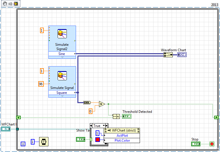
Take a look at the clip and see what I've added. Change the window size will change the threshold for filtering. I offset the result by one just to make it easier to see in the waveform graph.
-
How to convert the pulse signal line single layer
Hello
I tried to create a VI that will allow me to convert a pulse signal (generated by a tachometer) in a line single layer, indicating that a revolution succeeded. I would like to overlay this line on other signals generated.
I am able to detect the falling edge of the signal, but I could not make a suitable line. I tried to create a new waveform, and juggle the markers, but no method worked for me.
Does anyone have ideas for a good way to do this?
Below is my test VI.
Make the second vertical lines style trace (trace style: no points, no interpolation, fill - inf). a NaN whener you don't want a power cable and a '+ inf' when you want a vertical line.
Here's a simple example:

Maybe you are looking for
-
the computer not lee el device pues lo muestra como retribution y no encuentra los contraladores este mismo
-
Stop the flashing window BACK to the top when system Exec. called?
Hello If anyone knows how I can avoid having the DOS flash window upward when I run VI I joined: program that simply calls a .exe file. Thank you Marc XP & LV 8.5
-
How can I keep the original video sound?
I just want to combine both videos, but I want to keep the original sound. Is this possible?
-
Remember - this is a public forum so never post private information such as numbers of mail or telephone! Ideas: You have problems with programs Error messages Recent changes to your computer What you have already tried to solve the problem
-
Is there anyway easily re - download, or repair windows media player in Windows 7?
I don't want to have to redo my computer everything. My Windows Media Player does not recognize the discs of the DVD player. There must be an easier way. I don't see a link to download the reader on the Web site. Maybe someone knows how? Thank you.