differential measurement with a 6030e
If I have two signals and a desire to make a differential measure between the hot wires (not ground), how to set up the Board? It's supposed to make 16 differential measures completed or 8 single. In the latter case, this means that the device can be configured to make 8 differential measurements of 16 inputs?
Exo in the morning,
Using a differential connection is certainly a good way of measuring an analogue of entry, as you already understand that divide you by two the number of your channels when using differential, but it will prevent any problems of grounding that can occur (for example ground loops).
Knowledge according to article details the types of connection different http://zone.ni.com/devzone/cda/tut/p/id/3344 please refer to the "table 1: connection of the analogue input ' for more details on how to connect your circuit. I would recommend using the polarization resistance, but they are not vital for a differential connection.
Please do not hesitate to contact me if you need more help
Best regards
Tags: NI Hardware
Similar Questions
-
With differential measurement noise problems
Hey everybody.
I use an NI USB-6211, LABView 2011 and Win7.
I'm trying to measure a voltage through a resistor using differential mode. But unfortunately im getting a lot of noise (on + - 25%).
The voltage source I use is variable and can go up to 600V. With my diet I am essentially heat a metal plate.
A parallel voltage divider is used to reduce the voltage by one hundredth (1 MOhm and 10 kOhm).
Two wires attached to the lower resistance then go directly into analog input 0 + 8 of data acquisition.
So if I'm trained 600V to the plate, data acquisition should get about 6V... and that's what I measure with my voltmeter attached to the acquisition of data input pins.
I also tried these resistances of POLARIZATION and connected the + and - leads to the analogous to the ground like a resistance I used 10 k, 100 k and 1 MOhm and 2 MOhm and
continue to receive a bad signal.
Two sketches of the wire as a signal (100V, supposed to measure 1V, no CORRECTION) are attached to the post.
Concerning
EDIT: I forgot to write that I even tried an another NI DAQ and still get this noise problem.
Also, I measured the voltage source signal using an oscilloscope and I see that noise. But the differential mode isn't supposed to
reduce noise to a minimum?
Hey everybody,
come to understand that the voltage divider resistors are medium to high and they were the main reason for the noise
problem.
Before I used 1 MOhm and 10 kOhm, now I use 100 ohm and 100 kOhm and with a median filter in this regard, it works very well!
But still, if I use the resistance of these BIASES they do not change.
Concerning
-
Differential measurement across the ground of the card NOR referenced output.
Hello guys,.
I have a question, our pure curiosity.
I use map of USB6212 to apply a sinusoidal signal of 10V to a game to the top, then measure the tension between charges.
I'm attching here a simple diagram showing the system. The implementation can be modeled as a combination of RC - r series
Note that I'm also measure voltage R2 in differential mode. Now that I am after is exact phase of monitoring between the two voltages (according to the RC and the R2).
My question: is the correct diagram? I mean - is it OK to measure the voltage across R2 in differential mode with attached as such polarization resistors?
It is one of the lines through R2 is already at AOGND. And AIGND and AOGNd are already connected inside the card, it will be then introduced errors?
or does not at all?
Thanks guys, will be grateful for a quick solution.
You can do this but the differential mode does not have much. Your signal source is single ended. The voltage at the terminals of R1 - C can be measured in different ways. It really is meaningless to measure the voltage across R2 differently because one end is connected to the Earth. Polarization resistance, Rb, are not necessary in this case because the low enough impedance DC railways exist at all entrances.
What I would do, is make two measures ended up alone. AO1 measured on a single channel (AI0). Measure the R1 - R2 junction on the other channel (AI1). Then the input voltage is AI0, the voltage at the terminals of R1 - C is AI0 - AI1, and the current is AI1/R2. You will need to enjoy fast enough that the time between the different measures does not contribute too much to the phase error. It depends on your frequency of signal and eligible errors. Look at the charts of a waiting time to page 2 of the NI USB - 620 x specifications for more information on how to compromise between the speed, accuracy and multichannel source on measures resistance.
Lynn
-
220VAC measured with CompactDAQ?
Hi all
I'm building a testbed automated, where I need to measure both single-phase (120 and 277VAC) and two phases (208/240V ca... I am aware that nobody calls him two phases, but that's what you are actually measure... anywho) I have single phase works fine as seen in VI 'DAQ_Sample3', but when I try to apply the same logic to two legs of power my output is only sends me data for a leg. I went and added two other channels so it measures both legs and two amp clamps... I can connect the DAQ assistant for a graphical output and it shows all four readings, but when I'm trying to transition to power VI it will only calculate one leg. I have attempted to combine the signals from several different ways, but have not had a bit of luck to get a result that passes the test of reasonablilty... someone who knows a bit more on this taking a glance at the VI I for two can live (DAQ_Sample4-2ph) and point me in the right direction?
Thank you!
Chad
OK, well I finally realized what was going on... Apparently If connect you single phase (one leg and one neutral (120/277VAC) or legs (208-240 VAC) you must measure between a0 and a1 (differential measurement) and not on each leg to land is represented here...) http://zone.NI.com/DevZone/CDA/tut/p/ID/8216 For some reason any if you measure single phase 208-240 VAC and try to measure each leg down the numbers aren't right. I am now in a position through a channel and my numbers are dead on with my parser.
As a side note, that power might want to add more information to this series of videos... http://sine.NI.com/NIPs/CDs/view/p/lang/en/NID/208111 and comment on the actions of power for all single phase (120/277VAC and 208-240 VAC) should be taken on a single track on the module 9225. .. .or include a wiring diagram specific for various applications.
A big thank you to all who tried to help! I hope that this thread will save someone some time and frustration.
THX
Chad
-
Hello people,
I've read several documents on the site OR about the premium over common measures of mode and I think I understand, but I'm looking for confirmation through two examples (please).
Both examples assume a data acquisition card OR with +/-10V inputs and a maximum operating voltage of + / 11V (e.g. PCI-6052 with programmable gain 0.5).
Example 1: Suppose a DC voltage with two resistors divider and a differential input on the daq card configuration. First resistance = 4 Ohms connected to 100VDC, second resistance = 96 - grounded (0) Ohms. This results in a decline of 4VDC to the terminals of the first resistance. However, I believe that the differential voltage of 4VDC may be connected directly to the daq card because the absolute voltage (i.e. common mode?) is in fact 96VDC to 100VDC which is outside the "working range' of + / 11V for the card. This conclusion is correct?
Example 2: Suppose a differential measure between two AC signals and a differential input on the daq card configuration. First report = 25v@0deg, second signal = 10v@180deg. Some documents on the Web site of NOR, I gathered that the common mode voltage is the average of the vector representation of the input signals. In this case, it would be (25v@0deg + 10v@180deg) / 2 = 7.5v@0deg. I think that this signal can be directly connected to the daq card because one of the signals (25v@0deg) is outside the range of the card work (even if the result "means vectors" is within the scope of the map daq. This conclusion is correct?
Thanks in advance for any help,
chassan
Chassan,
You're right both of your examples. Is the best way to look at that is that even if you take a measure differential the maximum voltage you can submit a single channel to the + / 11V to the 6052E. Hope this clears things up a little bit.
-
Analog inputs measures with NI6229 using the DAQmx driver
Hello
I have four different analog inputs connected to ai0 to HW 6220 ai3. I read these values with a single task, all 4 channels assigned to this task. When ai0 reads 7V, I see 0.8 V ai1 too, but I expect to be measured 0V. If I just assign ai1 to the task and measure all 4 channels, then I measured 0V as expected (although ai1 contains 7V, I just don't measure it).
Another comment 'funny', is that if I change the order in which I add channels to the task, measurement errors are different.
However, when measured with a multimeter 4-channel show tensions as expected.
Given that my calling task is can not block, I call the function
DAQmxReadAnalogF64 with timeout = 0 and numSampsPerChan = 1.
Any help is appreciated.
Thank you
Kind regards
Deepa
Deepa,
Thanks for the code snippet.
When you call DAQmxReadAnalogF64 the first time and you set a value of timeout of 0, there is a chance that the acquisition is not yet initialized. This is the expected behavior and should not be a problem. If the timeout error died at the first call, you might ignore it or set a different expiration time for the first call only. In all cases, you should drop the first value and start with the second value.
Jochen
-
Balanced circuit differential measurement
I remember back to Labview 5 national had a great discussion tutorial white paper or knowledge base on how to understand the values of resistance when you perform a measurement of differential circuit. I have a PXI-6230. I can't find that anywhere now. Can someone point me to a discussion of the decent webpage on the calculation of the resisitors to differential measures?
Thank you... Clint
Hello
Please visit this link under the title "floating (nonreferenced) sources of measure."
Wiring and considerations of noise for analog signals
concerning
-
Measures with the date Conference
Hello
I have to make an application, as part of my end of study project, which allows to calculate heat flow. Pour this, I have data measured with thermocouples. These data are stored on a data recorder that record these data on a .txt, .xls or .csv file (it is to be chosen by user).
I'm not very chiseled with LabVIEW.
In a Prime Minister, I tried to read the .txt file data. I can read the 1st line as I wish but not others.
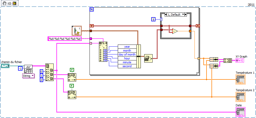
So I decided to work with a .xls file. The temperatures Conference goes smoothly. For time is the date, it's more complicated. Indeed, I would like to USE date and time corresponding to each measure to plot a graph XY with the date and time X and Y the temperature of the thermocouple.
Kind regards
Here's an example (VI from LV2011 but attached VI en LV2010) made on the basis of your code. Comment by watch it extract the news date and time of the string and generate the the from graph XY time in seconds in X. realized very quickly, it is without doubt room for improvement but you will serve as a basis for work at least.
To define 'Structure box' serving at first as far as being 0 and calculate relative time to the following samples. Thus the x-axis of the graph starts at 0.
My time is short, I renounce other comments but I happy to answer specific questions.
-
Hello:
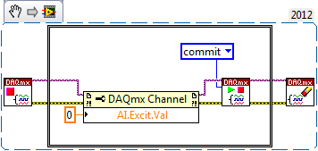
I am able accelerometers signals in a module of 9234, using DAQmx (I leave the joint scheme), which will be part of a program that will include other stages. When the acquisition is stopped by the "stop" button, I measure with a voltmeter between terminals connector BNC, reading 21 volts, which is the excitement of the sensor. My question is: How can I do to cut the excitement of sensors once the samples are acquired?Best regards
Jaime
Hi Jaime,
You can disable released the 9324 excitement by setting the AI. Excitation.Value property to 0.0 (see the following KB: http://digital.ni.com/public.nsf/allkb/3AD6CCE935192B4086256F6B0079CB1F).
Then, once you have set the attribute, you will incur the task to actually push this setting material (normally DAQmx will automatically engage when you start the job, but in this case, we do not want to start the task). Between your VI DAQmx stop task and your VI DAQmx clear task , you must add the following:
- GOT it node DAQmx channel property to set. Excit.Val = 0.0
- DAQmx controls Task.vi to validate your new task settings
-
HorizontalFieldManager Fix width automatic measurement with height
Hi all
I would like to make a HorizontalFieldManager with a fixed width, but automatic measurement with height. Do anyone with a good idea about it. Thanks for the help!
Thanks for your help!
Although your idea is a solution is not complete, it gives me a good idea to solve the problem.
My solution is to change my coding over a part of the first horizontalfieldmanger:HorizontalFieldManager hfm1 = new HorizontalFieldManager()
{
public int getPreferredWidth()
{
Returns the value 100;
}
protected void sublayout (int maxWidth, maxHeight int) {}
Super.sublayout (getPreferredWidth(), maxHeight);
LeftField RadioButtonField = getLeftButton();
If (leftField! = null & is equal to (leftField.getManager ())) {}
int x = 0;
int y = 0;
setPositionChild (leftField, x, y);
}
}
};
-
problems with the differential measure at labview2010
Hello!
IM using a 6063e card to measure and labview 2010, but I had a problem that I can not understand.
AI0 is differentiall (w. AI8) and AI2 is also differential (and short circuit just for test purpose). I posted a bad image of my connections. I think this is the simplest possible differential configuration. A source of energy that can be set between 0 - 8v is connected to AI0. (yellow and Red wire coming out of the image)
With example signals "Acq Cont & chart voltage-Int Clk.vi" I can measure and read plot map DAQ. Sampling channel AI0 works as expected, the voltage can be adjusted between 0 - 8v. Sampling AI2 also works as expected, nothing happens when I change the voltage on AI0. BUT if I sample both AI0 and AI2 and plot the AI2 signals gets on 2v when 8v are threaded AI0. Is no mather what example or my own code, the example above is just a suggestion to illustrate the problem. I tried the card on a different computer running labview 7.1, and all 3 cases works. I also tested to replace the map with a 6062e and it shows the same problems. Can someone please test this on their installation of labview 2010, I want to know if my installation is weird or labview 2010 is broken somehow. Could be a driver problem with series 60xx cards?
I solved my problem by sampling AI0 AI1, AI2 and simply ignore AI1. Weird but this market so I suspect some sort of driver bug.
-
6008 USB differential measure of floating resistance source & bias
Hello
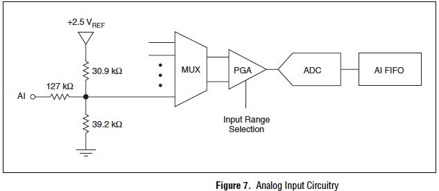
For some time now, I have been measuring the sources of floating signals such as transducers of linear speed (LVT) in differential mode by plugging directly into the differential inputs. The sensors have an impedance source of usually 1 k or less. I read recently that if you want to measure a floating source in differential mode, you must use polarization resistors, as recommended in a field here Guide. But I understand that the resistors are only to prevent entry of bias currents pushing beyond common-mode signals. The recommended values are 10-100 k. However, the 6008 already has 140 k input impedance, so I figure it's "close enough". I have not noticed any problems with the signals that I measured, at least in the sense where it oscillates back and forth between 0V and out don't max. What other kind of errors I would see in my signals?
So in this case the polarization resistors are really necessary?
Due to the input on the box USB-6008 circuits, it is unnecessary to use polarization that are required, resistors ofter on other devices with impedances of entry much higher. The picture below comes from page 16 of the document specification and User Guide.
Lynn
-
measure with the two channels of the virtual bench simultaneously in labview, error 375903
Hi, I am trying two measurements simultaneously using two channels of analog input of the virtual bench. I chose the channel MSO 1 and 2 for the measures but I get error 375903 returned evewry time say the requested resource is reserved. I'm not under any other software which should use the virtual bench. The error occurs when I'm initializing the session, even before a measurement was made. Can someone tell me how to call each channel so that I don't get this conflict of resource reservation?
I have included the VI and a screenshot of the error.
Thank you!
NGKai wrote:
Hi, I am trying two measurements simultaneously using two channels of analog input of the virtual bench. I chose the channel MSO 1 and 2 for the measures but I get error 375903 returned evewry time say the requested resource is reserved. I'm not under any other software which should use the virtual bench. The error occurs when I'm initializing the session, even before a measurement was made. Can someone tell me how to call each channel so that I don't get this conflict of resource reservation?
ASM takes only supported a session unique instrument and your VI uses two. To use both channels, delete the second session MSO and specify channels in the MSO configure Analog Channel.vi
Here's an example that uses two channels brought:
VirtualBench: Bode Analyzer with the FGEN and MSO
-
How to stop and restart a measurement with specific criteria?
Hey guys,.
I burn my brain trying to figure this problem on my program.
For my research project, I use an O2 sensor which is coupled to a Labjack U12 card and that's why I make a value of 4 mg/L, based on the switch to an electric socket (connected to the analog output) that is connected to the ventilation system. So when I 3.8 mg/L lights aeration and 4,2 turns off.
But I want to execute this measure for some time (maybe 10 minutes) and then stop the signal at the analogue output. After awhile the O2 measure will be reduced to values of 0 mg/L, but I want that when it reaches a specific value (perhaps 0.5 mg/L), is always idle for some time (maybe 2 min) and then again activates the signal at the analogue output (reboot cycle).
Is it possible to was this concept using Dasylab? I would be very grateful if you could help me with this!
I enclose 2 photos, the real configuration of my block Dasylab and the other is the extent expected after the new configuration.
Hugs and Outlook for the suggestions.
Celso
Is the curve in the diagram of the output of the "Labjack: AI"-module?
You can then use the following series of blocks:
Direct the signal of the Labjack-block in a block-combitrigger: Start-event is when the signal is less than 0.5, Stop-event is when the value exceeds 0.5 (do NOT use events "is less to ' / ' exceeds '!).
Connect the trigger block to a block Counter, which counts both the signal received (from the trigger-block) is TTL-high.
Use another trigger-block just after the block Counter: beginning-event is when the signal exceeds {insert time in seconds}, Stop-event is "live".
Now connect a block action, which controls the ventilation switch corresponding (light: curve rises, turn off: curve drops - is this correct?), the action should be triggered, if the signal of the previous block put on a rising.
How to control the measurement time of 10 min with meter,-relaxation, switch-action-modules and is left as work at home.

-
temperature measurement with labview on four location using NTC thermistor
Hello
My project is the measure of the temperature of a thermistor on-site 4 difference.
The measures must be 0 for 100 * C.details.
- For the sensor, I must use only NTC thermistor.
- I have to do an application with Labview.
- the application must give me the right measure in real time, and it should save the sample in a database.
- This measure is taken max 20 feet form the pc.
I'm new with this.
Can someone help me with sensor circuits.
How can use DAQ with the thermistor.
Can I use EMANT300 Low-Cost USB DAQ Module 24 bit?Please give an idea
Maybe you are looking for
-
How can I remove the page options for my home pages when I use several home pages?
I used several pages to my homepage with FireFox for a long time. I've recently updated my homepage as always - "use current pages" - now the firefox open the options page and which ones I want. It is not listed in the list of pages to open as home p
-
Is it possible to change the snapshots naming convention? Work on a shared storage system uses NTFS on the back end so "/" is a character not consistent therefore generate snapshots fail.
-
When closing a page, a 3-inch square rest on the screen.
Original title: problems When I close my pages, there is a 3 "x 3" square on my desktop and I can't get rid of it. Also when I shut down the computer, it begins to shut down but crashes and a message, "this program is not responding" Please help.
-
BitLocker Drive preparation tool - fail
Hello So, I try to activate bitlocker on my laptop drive encryption, which is already running Vista Ultimate x 86. I was not initially intended, and I knew that if I wanted to later, I could allagedly use the Bitlocker Drive preparation tool, so I b
-
get an error when the computer shuts down say reinstall Extender player. ? What is it. Thank you