Balanced circuit differential measurement
I remember back to Labview 5 national had a great discussion tutorial white paper or knowledge base on how to understand the values of resistance when you perform a measurement of differential circuit. I have a PXI-6230. I can't find that anywhere now. Can someone point me to a discussion of the decent webpage on the calculation of the resisitors to differential measures?
Thank you... Clint
Hello
Please visit this link under the title "floating (nonreferenced) sources of measure."
Wiring and considerations of noise for analog signals
concerning
Tags: NI Hardware
Similar Questions
-
differential measurement with a 6030e
If I have two signals and a desire to make a differential measure between the hot wires (not ground), how to set up the Board? It's supposed to make 16 differential measures completed or 8 single. In the latter case, this means that the device can be configured to make 8 differential measurements of 16 inputs?
Exo in the morning,
Using a differential connection is certainly a good way of measuring an analogue of entry, as you already understand that divide you by two the number of your channels when using differential, but it will prevent any problems of grounding that can occur (for example ground loops).
Knowledge according to article details the types of connection different http://zone.ni.com/devzone/cda/tut/p/id/3344 please refer to the "table 1: connection of the analogue input ' for more details on how to connect your circuit. I would recommend using the polarization resistance, but they are not vital for a differential connection.
Please do not hesitate to contact me if you need more help
Best regards
-
Hello people,
I've read several documents on the site OR about the premium over common measures of mode and I think I understand, but I'm looking for confirmation through two examples (please).
Both examples assume a data acquisition card OR with +/-10V inputs and a maximum operating voltage of + / 11V (e.g. PCI-6052 with programmable gain 0.5).
Example 1: Suppose a DC voltage with two resistors divider and a differential input on the daq card configuration. First resistance = 4 Ohms connected to 100VDC, second resistance = 96 - grounded (0) Ohms. This results in a decline of 4VDC to the terminals of the first resistance. However, I believe that the differential voltage of 4VDC may be connected directly to the daq card because the absolute voltage (i.e. common mode?) is in fact 96VDC to 100VDC which is outside the "working range' of + / 11V for the card. This conclusion is correct?
Example 2: Suppose a differential measure between two AC signals and a differential input on the daq card configuration. First report = 25v@0deg, second signal = 10v@180deg. Some documents on the Web site of NOR, I gathered that the common mode voltage is the average of the vector representation of the input signals. In this case, it would be (25v@0deg + 10v@180deg) / 2 = 7.5v@0deg. I think that this signal can be directly connected to the daq card because one of the signals (25v@0deg) is outside the range of the card work (even if the result "means vectors" is within the scope of the map daq. This conclusion is correct?
Thanks in advance for any help,
chassan
Chassan,
You're right both of your examples. Is the best way to look at that is that even if you take a measure differential the maximum voltage you can submit a single channel to the + / 11V to the 6052E. Hope this clears things up a little bit.
-
problems with the differential measure at labview2010
Hello!
IM using a 6063e card to measure and labview 2010, but I had a problem that I can not understand.
AI0 is differentiall (w. AI8) and AI2 is also differential (and short circuit just for test purpose). I posted a bad image of my connections. I think this is the simplest possible differential configuration. A source of energy that can be set between 0 - 8v is connected to AI0. (yellow and Red wire coming out of the image)
With example signals "Acq Cont & chart voltage-Int Clk.vi" I can measure and read plot map DAQ. Sampling channel AI0 works as expected, the voltage can be adjusted between 0 - 8v. Sampling AI2 also works as expected, nothing happens when I change the voltage on AI0. BUT if I sample both AI0 and AI2 and plot the AI2 signals gets on 2v when 8v are threaded AI0. Is no mather what example or my own code, the example above is just a suggestion to illustrate the problem. I tried the card on a different computer running labview 7.1, and all 3 cases works. I also tested to replace the map with a 6062e and it shows the same problems. Can someone please test this on their installation of labview 2010, I want to know if my installation is weird or labview 2010 is broken somehow. Could be a driver problem with series 60xx cards?
I solved my problem by sampling AI0 AI1, AI2 and simply ignore AI1. Weird but this market so I suspect some sort of driver bug.
-
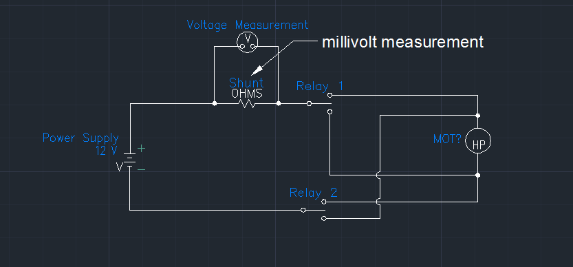
differential measurement high voltage
Not sure if this is the best place, but here goes.
We are trying to measure a voltage differential across a shunt in offset voltage, which is then further +/-10V over data acquisition cards measure. Here's a representative diagram of our circuit:
We must also measure 24 of these shunts while we move the motor one way or the other. That in one case the offset voltage is near current of 12 volts (rank 9-16Vcc) that eliminates all the cards of the cDAQ and it looks like the PXI series too. We currently use one SCXI-1104 researcher but a USB port on a laptop for this measure. The SCXI-1104 has a voltage range of + / 60V and I was unable to find anything close to that in the product offerings of NOR. The reason why this is going to be a problem for us is that large corporation, we are forced to move to windows 7-64 bit and SCXI hardware are not supported for this operating system.
I am open to any suggestions that others may have to help us fix this problem.
Thank you
Bill Lane
We ended up finding some amplifiers that have been specifically designed for the high pressure shunts. Do a search on digikey for amplifier of high-side current shunt and you should be able to find something. These will turn the measure into a single measure is over voltage.
-
6008 USB differential measure of floating resistance source & bias
Hello
For some time now, I have been measuring the sources of floating signals such as transducers of linear speed (LVT) in differential mode by plugging directly into the differential inputs. The sensors have an impedance source of usually 1 k or less. I read recently that if you want to measure a floating source in differential mode, you must use polarization resistors, as recommended in a field here Guide. But I understand that the resistors are only to prevent entry of bias currents pushing beyond common-mode signals. The recommended values are 10-100 k. However, the 6008 already has 140 k input impedance, so I figure it's "close enough". I have not noticed any problems with the signals that I measured, at least in the sense where it oscillates back and forth between 0V and out don't max. What other kind of errors I would see in my signals?
So in this case the polarization resistors are really necessary?
Due to the input on the box USB-6008 circuits, it is unnecessary to use polarization that are required, resistors ofter on other devices with impedances of entry much higher. The picture below comes from page 16 of the document specification and User Guide.
Lynn
-
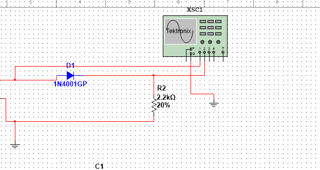
half-wave rectified filter circuit/oscilloscope measurement
Hello everyone, I hope I can get help on this fundamental issue, I'll have. University online, with which I will not help me, so I hope that I can quickly get assistance here.
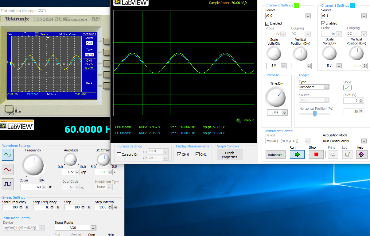
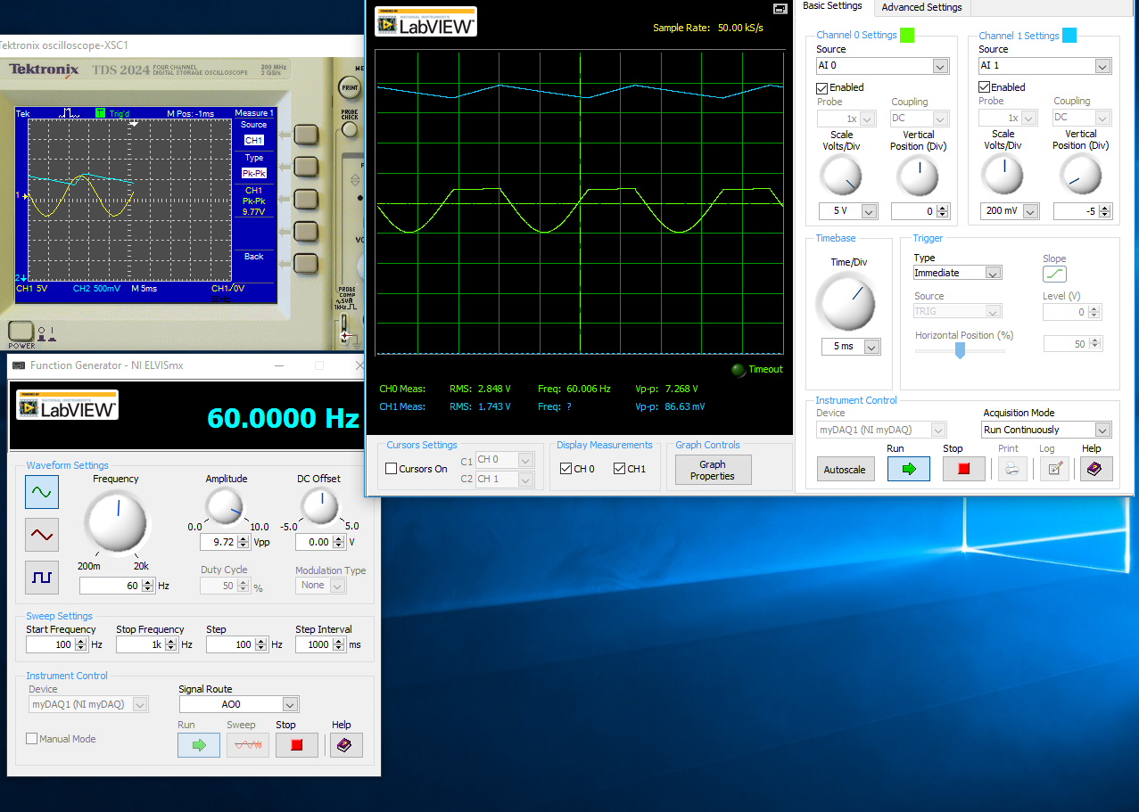
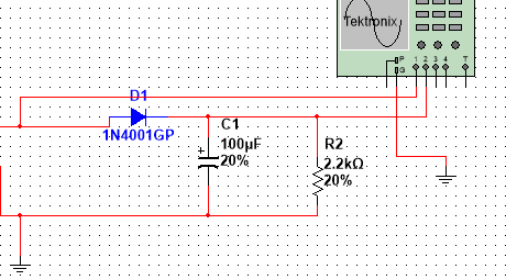
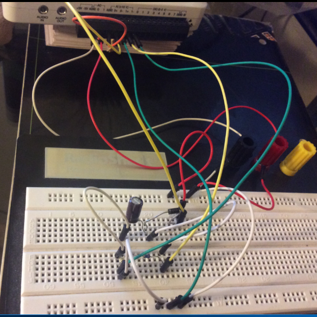
I have the myDAQ NOR, I have to build half rectified filter circuit with a resistance 2.2kOhm, I also use the multi-sim to confirm the measures of waveform. Everything goes well on Labview multisims Tektronix Oscilloscope compared to before I connect a capacitor 100uF my comparison heres:
The model is just the Diode with a series resistance 2.2kOhm, I'm not sure if the analog inputs to the LabView Oscilloscope are configured correctly this is the air I get:
This satifies my simple comparison on the Multisim circuit, since I came here for a few hours to play with probes analog input, I know that something is wrong out of these measures, I get.
With a capacitor 100uF in parallel:
I think the question is how I inputs analog and STILL plugged, I'm not sure that this is where I would really like some help or any type of assistance. Once I get this set up right, I'll be able to take measures for the frequency, load DC, P - P Ripple voltage ripple and then move to a full-wave rectified circuit. I just started a course and received the myDAQ.
Henrik_Volkers wrote:
Compare it with the current specification of output of your myDAQ

Here is a link to the specification: http://www.ni.com/pdf/manuals/373061f.pdf
Henrik hit it on the head. The myDAQ can, at most, out 2mA with analog output. So, with a 2.2kOhm charge, which puts you in 4.4V without the diode. The led will also require an amount of current. According to my estimates, subject of 1mA (your pic is ~2.5V, divide by the 2.2kOhm to get ~ 1mA). You will see only that on the positive side of the sine wave as the diode blocks all the negative side.
The lesson here is to make sure that your outputs have enough power to do what you want. You can go to get a simple op-amp from digikey and use a follower of tension for editing the current upward. You will probably need another power supply or two (+ 12V and - 12V) to power op-amp.
-
Differential measurement across the ground of the card NOR referenced output.
Hello guys,.
I have a question, our pure curiosity.
I use map of USB6212 to apply a sinusoidal signal of 10V to a game to the top, then measure the tension between charges.
I'm attching here a simple diagram showing the system. The implementation can be modeled as a combination of RC - r series
Note that I'm also measure voltage R2 in differential mode. Now that I am after is exact phase of monitoring between the two voltages (according to the RC and the R2).
My question: is the correct diagram? I mean - is it OK to measure the voltage across R2 in differential mode with attached as such polarization resistors?
It is one of the lines through R2 is already at AOGND. And AIGND and AOGNd are already connected inside the card, it will be then introduced errors?
or does not at all?
Thanks guys, will be grateful for a quick solution.
You can do this but the differential mode does not have much. Your signal source is single ended. The voltage at the terminals of R1 - C can be measured in different ways. It really is meaningless to measure the voltage across R2 differently because one end is connected to the Earth. Polarization resistance, Rb, are not necessary in this case because the low enough impedance DC railways exist at all entrances.
What I would do, is make two measures ended up alone. AO1 measured on a single channel (AI0). Measure the R1 - R2 junction on the other channel (AI1). Then the input voltage is AI0, the voltage at the terminals of R1 - C is AI0 - AI1, and the current is AI1/R2. You will need to enjoy fast enough that the time between the different measures does not contribute too much to the phase error. It depends on your frequency of signal and eligible errors. Look at the charts of a waiting time to page 2 of the NI USB - 620 x specifications for more information on how to compromise between the speed, accuracy and multichannel source on measures resistance.
Lynn
-
With differential measurement noise problems
Hey everybody.
I use an NI USB-6211, LABView 2011 and Win7.
I'm trying to measure a voltage through a resistor using differential mode. But unfortunately im getting a lot of noise (on + - 25%).
The voltage source I use is variable and can go up to 600V. With my diet I am essentially heat a metal plate.
A parallel voltage divider is used to reduce the voltage by one hundredth (1 MOhm and 10 kOhm).
Two wires attached to the lower resistance then go directly into analog input 0 + 8 of data acquisition.
So if I'm trained 600V to the plate, data acquisition should get about 6V... and that's what I measure with my voltmeter attached to the acquisition of data input pins.
I also tried these resistances of POLARIZATION and connected the + and - leads to the analogous to the ground like a resistance I used 10 k, 100 k and 1 MOhm and 2 MOhm and
continue to receive a bad signal.
Two sketches of the wire as a signal (100V, supposed to measure 1V, no CORRECTION) are attached to the post.
Concerning
EDIT: I forgot to write that I even tried an another NI DAQ and still get this noise problem.
Also, I measured the voltage source signal using an oscilloscope and I see that noise. But the differential mode isn't supposed to
reduce noise to a minimum?
Hey everybody,
come to understand that the voltage divider resistors are medium to high and they were the main reason for the noise
problem.
Before I used 1 MOhm and 10 kOhm, now I use 100 ohm and 100 kOhm and with a median filter in this regard, it works very well!
But still, if I use the resistance of these BIASES they do not change.
Concerning
-
PXI-6230 and differential measures
Can you use the 6230 for closed measures the differential and unique at the same time? Only 2 measures for Diff and 10 for itself? What do I have to configure it somehow in MAX?
Thank you.
Of course, you can mix the types of channels, although the 6230 has only 4diff/8se and not the number you mention. You can do it in MAX or in your code. In MAX, just select the configuration of terminal for each channel. I know not what programming language used because you don't mention it, but if it is LabVIEW, you use just a function separate from DAQmx create channel for different channels and themselves. Don't forget to take into account that each diff channel requires two real physical channels. So, if you select ai0 for diff, which also uses ai4.
-
I just built a remote DMVPN RADIUS with an 300Mbps private point-to-point circuit to the data center. My manager has promised an SLA of< 20ms="" at="" 50%="" bandwidth="" utilization="" (i="" think="" he="" made="" that="" up?!).="" i'm="" trying="" to="" sort="" out="" the="" best="" way="" to="" test/document/baseline="" this="" statement="" for="" the="" customer.="" my="" questions="">
Can how best I simulate a 50% load on the circuit? -My thoughts would be to set up some sort of maximum bandwidth QoS between 2 hosts and push then a large amount of traffic across the link and then average latency statistics ICMP to ping between the same two hosts.
Without going into too much detail, the remote site is using ASR1001 (DMVPN spoke) with tunnel interfaces ASR1002 worms (DMVPN hub). 3750 x at the access layer.
3750 x > mm fiber > asr1001 (speak) > 300Mbps circuit > 3750 x > asr1002 (hub) > l ' infrastructure.
Thanks in advance!
On the client side of Iperf use the-b option to specify the available bandwidth. [UDP]
I hope this helps.
See here:
http://OpenManiak.com/Iperf.php
UDP tests: (-u), bandwidth settings (-b)
Also see the section "Jperf.UDP tests with the argument u will give valuable information on the jitter and packet loss. If you do not specify the argument - u, Iperf uses the TCP protocol.
To keep a good quality link, the packet loss should not go more than 1%. A high packet loss rates will generate a lot of retransmissions of TCP segment that will have an impact on bandwidth.The Jig is basically the variation in latency and doesn't depend on the latency. You can have high response times and a very low jitter. The jitter value is especially important on network links supporting voice over IP (VoIP) as a high jitter can interrupt a call.
The argument-b allows the allocation if the desired bandwidth. Client side:
10.1.1.1-c #iperf u b 10 m ------------------------------------------------------------
Client that connects to 10.1.1.1, port UDP 5001
Send datagrams 1470 bytes
The UDP buffer size: 108 KB (default value)
------------------------------------------------------------
[3] 10.6.2.5 local port 32781 connected with 10.1.1.1 port 5001
[3] 0, 0 - dry 10.0 11.8 MB 9.89 Mbps
[3] send datagrams 8409
[3] the server report:
[3] 0, 0 - dry 10.0 11.8 MB 9.86 Mbps 2,617 ms 9 / 8409 (0.11%)Server-side:#iperf s u-i 1 ------------------------------------------------------------
Server that is listening on port UDP 5001
Receipt of datagrams 1470 bytes
The UDP buffer size: 8.00 KByte (default)
------------------------------------------------------------
[904] 10.1.1.1 local port 5001 connected with 10.6.2.5 port 32781
[ID] interval transfer band jitter bandwidth Total lost datagrams
[904] 0,0-1,0 s 1.17 Mbps ms 1,830 9.84 MB 0 / 837 (0%)
[904] 1.0-2.0 sec 1.18 MB 9.94 Mbps 1,846 ms 5 / 850 (0.59%)
[904] 2.0-3.0 s 1.19 MB 9.98 Mbps 1,802 ms 2 / 851 (0.24%)
[904] 3.0-4.0 sec 1.19 MB 10.0 Mbit/s ms 1,830 0 / 850 (0%)
[904] 4.0-5.0 sec 1.19 MB 9.98 Mbps 1,846 ms 1 / 850 (0.12%)
[904] 5.0-6.0 sec 1.19 MB 10.0 Mbps 1,806 ms 0 / 851 (0%)
[904] 6,0-7,0 sec 1.06 MB 8.87 Mbps 1,803 ms 1 / 755 (0.13%)
[904] 7.0-8.0 sec 1.19 MB 10.0 Mbit/s ms 1,831 0 / 850 (0%)
[904] 8.0-9.0 sec 1.19 MB 10.0 Mbps 1.841 ms 0 / 850 (0%)
[904] 9, 0-10, 0 sec 1.19 MB 10.0 ms 1,801 Mbits/sec 0 / 851 (0%)
[904] 0, 0 - dry 10.0 11.8 MB 9.86 Mbps 2,618 ms 9 / 8409 (0.11%) -
myRIO - measure unique output completed using differential input
Hi all
I had used myRIO 1900 to measure the power of the microphone, which varies from 0 to 5V (biased to 2, 5V).
I used one of the analog input ports completed only connector MXP or B to read the value.
A few reasons, I changed the microphone with amplifier and when measured using oscilloscope and other hardware DAQ, supply range of + 5V and - 5V.
As the MXP is unable to read the voltage-ve, I realized that I need to change the connection to the MSP connector C.
It is mentioned in the dataheet of myRIO we can measure up to differential Channels analog input +/-10 V.
Although there are some reference materials available, I do not understand completely how to read the single ended output using differential input.
Should I use no matter what op-amp or comes directly from their phone?
Can someone kindly explain to me the differences and some references on how to connect!
Although I tried to read through this white paper, I felt completely lost

http://www.NI.com/white-paper/3344/en/
Exit ended unique direct and/or the amplifier has 2 pins: GND and Vout
Entered different a 3-pin: A +, A - and ALWAYS
I had attached the screenshot of the form OP amp for your reference
I think that you just connect your Vout to the + ve differential termination, MASS to Terminal - ve. (Briefly) An asymmetric measure is between the channel of GOT it and STILL while a differential measurement is between the + ve and ve - terminal. One measurement unit completed is referenced to GND is where you are measuring the tension of.
-
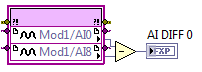
6225 DAQmx names for measurements of the differential pair
All,
I came across this post trying to find out if there was documentation to show who's analog inputs are coupled together and what name DAQmx controls call these pairs.
Messages from the author a drawing which I think is correct, but it is not an official document of OR. I'm looking for documents that says exactly what the name is for each pair during their use in a command DAQmx. I know literature 6225 AI0 and AI8 form a pair, and AI1 and AI9 are a pair, etc. etc. What I was trying to find, is documentation that shows that the name of each of these pairs, what I should do in the DAQmx calls during a differential measure. Currently, I am assuming that the AI0/AI8 pair is referred to as AI0 when the measure differential. I have just followed the list of pairs in the manual of the user from left to right and from top to bottom and naming of AI0 to AI39. I really was hoping that there was an official document that says what were the names of each differential pair.
Can you point me to the appropriate document or tell me that it is not an and that my assumptions are correct?
Thank you!
Doug
Doug,
There is not an official document similar to the one in the related post that shows the AI0 + and AI0-. The differential channel will always be referred to by the positive terminal. It doesn't matter what differential channel number it is. For example, the Channel 9 differential uses AI16 as the positive terminal. All configurations in DAQmx must be configured using AI16 in differential mode. The drawing was published is not official, but it is correct.
Kind regards
Danny F
-
Measurement of the conductivity of the ground
Hi all
I'm trying to measure the conductivity of the ground using the Wenner table method. The attached photo is meant. I have a Board that generates an alternating voltage. The tension is provided in the ground using two socs (a round plate, partially buried in the ground and tied behind a farm tractor). Between these two points, I have an another two plowshares to measure the potential difference between these two points. Regarding the measure, I will need to measure the current voltage power and the potential difference. I use USB-6215. I put a known resistance in series along a leg of the alternating voltage. The idea is to measure the voltage at the terminals of the resistance (and so I can get current) given that USB-6215 is unable to measure current directly.
Now, my question is, in my view, a simple. I got confused on the connection I need to use. I know that I need to use differential measures to measure both the current and potential difference. However, referring to the guidelines for field wiring of NOR have (http://zone.ni.com/devzone/cda/tut/p/id/3344), I do not know if my case is considered updating the Earth or floating signal source.
Tips are appreciated!
Hi Lan 78,
Is based on the signal of your signal.
I therefore recommend differential connection.
However, there are a few things you need to know:
1. ensure that the voltage at the terminals of resistance exceeds 10V.
2. 6215 is a bus isolated, no channel-to-channel isolation. Therefore, if you measure a large voltage on several channels, he probably break down of the device.
3 bus isolated from 6125 is 30Vrms. ensure you that it does not exceed this requirement.
Sincerely, Kate
-
Differential using NI 9205 using FPGA
If I need to make a differential measurement, do I need to subtract the corresponding entry to this?
(This could be executed on FPGA)
Are there problems (such as clipping) if my input range is small, lets say ±200mV but my IO is floating in, say, 3.0V on AI0 and 3.1V on AI8?
To take a differential measurement with FPGA, you first need to go to your project and right-click on the module and access its properties. You should see a list of all your channels, as well as their input range and terminal mode. The value the + channel for everything that match you are eager to use it as DIFF and file I/O node just to the canal +. You don't have to do a manual removal.
Not expect problems with the behavior you described.
Maybe you are looking for
-
This occurs after the log on screen is displayed. The display will lit in blue and will not display anything. I can not even boot mode safe. After I pressed on not to send to Microsoft, nothing happens. I may have a virus. Please notify.
-
Adjustment of the farm for all users
My apologies if I missed this answered somewhere, but I couldn't find it anyway. I have a thin client, running vWorkspace AppPortal 8.0. Users to connect individually as opposed to a shared connection. Is it possible for me to load the configuration
-
Is there anyway easily re - download, or repair windows media player in Windows 7?
I don't want to have to redo my computer everything. My Windows Media Player does not recognize the discs of the DVD player. There must be an easier way. I don't see a link to download the reader on the Web site. Maybe someone knows how? Thank you.
-
BlackBerry Smartphones Blackberry storm 2 9520
Someone knows how to do a full format on the phone and re - install the new OS to change carriers and to get rid of the default enterprise server
-
Acrobat DC keeps freezing on Mac
I installed acrobat that sews Pro DC via creative application on mac, but it keeps freezing. In fact, it will still not open. I also installed Acrobat Reader DC and the same problem happened. The application does not open.