220VAC measured with CompactDAQ?
Hi all
I'm building a testbed automated, where I need to measure both single-phase (120 and 277VAC) and two phases (208/240V ca... I am aware that nobody calls him two phases, but that's what you are actually measure... anywho) I have single phase works fine as seen in VI 'DAQ_Sample3', but when I try to apply the same logic to two legs of power my output is only sends me data for a leg. I went and added two other channels so it measures both legs and two amp clamps... I can connect the DAQ assistant for a graphical output and it shows all four readings, but when I'm trying to transition to power VI it will only calculate one leg. I have attempted to combine the signals from several different ways, but have not had a bit of luck to get a result that passes the test of reasonablilty... someone who knows a bit more on this taking a glance at the VI I for two can live (DAQ_Sample4-2ph) and point me in the right direction?
Thank you!
Chad
OK, well I finally realized what was going on... Apparently If connect you single phase (one leg and one neutral (120/277VAC) or legs (208-240 VAC) you must measure between a0 and a1 (differential measurement) and not on each leg to land is represented here...) http://zone.NI.com/DevZone/CDA/tut/p/ID/8216 For some reason any if you measure single phase 208-240 VAC and try to measure each leg down the numbers aren't right. I am now in a position through a channel and my numbers are dead on with my parser.
As a side note, that power might want to add more information to this series of videos... http://sine.NI.com/NIPs/CDs/view/p/lang/en/NID/208111 and comment on the actions of power for all single phase (120/277VAC and 208-240 VAC) should be taken on a single track on the module 9225. .. .or include a wiring diagram specific for various applications.
A big thank you to all who tried to help! I hope that this thread will save someone some time and frustration.
THX
Chad
Tags: NI Hardware
Similar Questions
-
Analog inputs measures with NI6229 using the DAQmx driver
Hello
I have four different analog inputs connected to ai0 to HW 6220 ai3. I read these values with a single task, all 4 channels assigned to this task. When ai0 reads 7V, I see 0.8 V ai1 too, but I expect to be measured 0V. If I just assign ai1 to the task and measure all 4 channels, then I measured 0V as expected (although ai1 contains 7V, I just don't measure it).
Another comment 'funny', is that if I change the order in which I add channels to the task, measurement errors are different.
However, when measured with a multimeter 4-channel show tensions as expected.
Given that my calling task is can not block, I call the function
DAQmxReadAnalogF64 with timeout = 0 and numSampsPerChan = 1.
Any help is appreciated.
Thank you
Kind regards
Deepa
Deepa,
Thanks for the code snippet.
When you call DAQmxReadAnalogF64 the first time and you set a value of timeout of 0, there is a chance that the acquisition is not yet initialized. This is the expected behavior and should not be a problem. If the timeout error died at the first call, you might ignore it or set a different expiration time for the first call only. In all cases, you should drop the first value and start with the second value.
Jochen
-
Measures with the date Conference
Hello
I have to make an application, as part of my end of study project, which allows to calculate heat flow. Pour this, I have data measured with thermocouples. These data are stored on a data recorder that record these data on a .txt, .xls or .csv file (it is to be chosen by user).
I'm not very chiseled with LabVIEW.
In a Prime Minister, I tried to read the .txt file data. I can read the 1st line as I wish but not others.
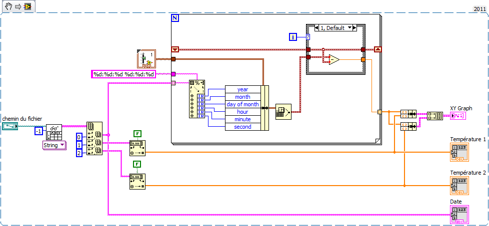
So I decided to work with a .xls file. The temperatures Conference goes smoothly. For time is the date, it's more complicated. Indeed, I would like to USE date and time corresponding to each measure to plot a graph XY with the date and time X and Y the temperature of the thermocouple.
Kind regards
Here's an example (VI from LV2011 but attached VI en LV2010) made on the basis of your code. Comment by watch it extract the news date and time of the string and generate the the from graph XY time in seconds in X. realized very quickly, it is without doubt room for improvement but you will serve as a basis for work at least.
To define 'Structure box' serving at first as far as being 0 and calculate relative time to the following samples. Thus the x-axis of the graph starts at 0.
My time is short, I renounce other comments but I happy to answer specific questions.
-
Hello:
I am able accelerometers signals in a module of 9234, using DAQmx (I leave the joint scheme), which will be part of a program that will include other stages. When the acquisition is stopped by the "stop" button, I measure with a voltmeter between terminals connector BNC, reading 21 volts, which is the excitement of the sensor. My question is: How can I do to cut the excitement of sensors once the samples are acquired?Best regards
Jaime
Hi Jaime,
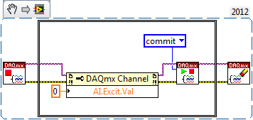
You can disable released the 9324 excitement by setting the AI. Excitation.Value property to 0.0 (see the following KB: http://digital.ni.com/public.nsf/allkb/3AD6CCE935192B4086256F6B0079CB1F).
Then, once you have set the attribute, you will incur the task to actually push this setting material (normally DAQmx will automatically engage when you start the job, but in this case, we do not want to start the task). Between your VI DAQmx stop task and your VI DAQmx clear task , you must add the following:
- GOT it node DAQmx channel property to set. Excit.Val = 0.0
- DAQmx controls Task.vi to validate your new task settings
-
HorizontalFieldManager Fix width automatic measurement with height
Hi all
I would like to make a HorizontalFieldManager with a fixed width, but automatic measurement with height. Do anyone with a good idea about it. Thanks for the help!
Thanks for your help!
Although your idea is a solution is not complete, it gives me a good idea to solve the problem.
My solution is to change my coding over a part of the first horizontalfieldmanger:HorizontalFieldManager hfm1 = new HorizontalFieldManager()
{
public int getPreferredWidth()
{
Returns the value 100;
}
protected void sublayout (int maxWidth, maxHeight int) {}
Super.sublayout (getPreferredWidth(), maxHeight);
LeftField RadioButtonField = getLeftButton();
If (leftField! = null & is equal to (leftField.getManager ())) {}
int x = 0;
int y = 0;
setPositionChild (leftField, x, y);
}
}
};
-
Measurment LVDT DC with CompactDAQ
Hello
I am currently working with reading as a result of an LVDT for a project that the present model is the DC LVDT Omega LD620-25
According to the data sheet's model requires a voltage of 10-30 v and a maximum current of 25ma
http://www.Omega.com/pptst/LD620.html
with regard to the available data acquisition modules: the NI 9237 and the 9220 OR by using a module compactDAQ
as the NI9237 has an internal output of 150mW obtained maximum current is 15ma, simply use?
the 9220 OR will be used for the acquisition of data but provides no port of excitement!
as for the solution another I thought using an AC adapter / CC of normal 12Vdc 100ma with a variable pot or a circuit voltage divider to provide the necessary tension
but I have several concerns with respect to the Earth circuit. in this system, I will have two independent reasons!
What will be the best solution to connect the LVDT module to the 9220 OR and provide a source of external excitation?
Thank you
Hello ghattas.ak
Consider the NI 9218. It can provide 12V exictation to ~ 50 mA per channel and read 5 or output 10V DC LVDT. To use this excitement 12V, 9 - 30V power supply must be connected at the Vsup pins. As you said, you can also use the 9220 OR with external excitation. The NI 9237 measuring range of +/-25 mV/V does not cover the 5 or 10 v output sensor you.
See you soon,.
Izzy O.
Product Support Engineer
National Instruments
NI.com/support
-
Measurement of voltage and the voltage with CompactDAQ display?
OK, I just got my CompactDAQ hooked up with two modules (9225, 9239) and am able to simple single-phase voltage (120 VAC)... I connected an indicator, and it gives me shooting random sine wave values and what I'm looking for a simple voltage reading. MAX and the DAQ assistant both work very well to the configuration task and I can see the signal in there.
I dug through the DAQmx, watched functions in the knowledge base and have searched here without any real results. I also downloaded the EPM resource kit, but it's tools for further on the road... It seems to me that this should be simple crazy, but maybe I go too hard or just looking is not in the right place? I would greatly appreciate a point in the right direction!
Thank you!
Chad
With the help of... Windows XP (SP3), LabVIEW 2009, cDAQ-9174, 9225, 9239.
Chad,
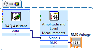
When you say "simple voltage readout" are you referring to the effective voltage of the AC signal? If Yes, you can use the Express VI 'Amplitude and level measures' to calculate the desired value.
Hope this helps, otherwise if specify you what you are looking for a little I will try again.
~ SimonH
-
measure with the two channels of the virtual bench simultaneously in labview, error 375903
Hi, I am trying two measurements simultaneously using two channels of analog input of the virtual bench. I chose the channel MSO 1 and 2 for the measures but I get error 375903 returned evewry time say the requested resource is reserved. I'm not under any other software which should use the virtual bench. The error occurs when I'm initializing the session, even before a measurement was made. Can someone tell me how to call each channel so that I don't get this conflict of resource reservation?
I have included the VI and a screenshot of the error.
Thank you!
NGKai wrote:
Hi, I am trying two measurements simultaneously using two channels of analog input of the virtual bench. I chose the channel MSO 1 and 2 for the measures but I get error 375903 returned evewry time say the requested resource is reserved. I'm not under any other software which should use the virtual bench. The error occurs when I'm initializing the session, even before a measurement was made. Can someone tell me how to call each channel so that I don't get this conflict of resource reservation?
ASM takes only supported a session unique instrument and your VI uses two. To use both channels, delete the second session MSO and specify channels in the MSO configure Analog Channel.vi
Here's an example that uses two channels brought:
VirtualBench: Bode Analyzer with the FGEN and MSO
-
How to stop and restart a measurement with specific criteria?
Hey guys,.
I burn my brain trying to figure this problem on my program.
For my research project, I use an O2 sensor which is coupled to a Labjack U12 card and that's why I make a value of 4 mg/L, based on the switch to an electric socket (connected to the analog output) that is connected to the ventilation system. So when I 3.8 mg/L lights aeration and 4,2 turns off.
But I want to execute this measure for some time (maybe 10 minutes) and then stop the signal at the analogue output. After awhile the O2 measure will be reduced to values of 0 mg/L, but I want that when it reaches a specific value (perhaps 0.5 mg/L), is always idle for some time (maybe 2 min) and then again activates the signal at the analogue output (reboot cycle).
Is it possible to was this concept using Dasylab? I would be very grateful if you could help me with this!
I enclose 2 photos, the real configuration of my block Dasylab and the other is the extent expected after the new configuration.
Hugs and Outlook for the suggestions.
Celso
Is the curve in the diagram of the output of the "Labjack: AI"-module?
You can then use the following series of blocks:
Direct the signal of the Labjack-block in a block-combitrigger: Start-event is when the signal is less than 0.5, Stop-event is when the value exceeds 0.5 (do NOT use events "is less to ' / ' exceeds '!).
Connect the trigger block to a block Counter, which counts both the signal received (from the trigger-block) is TTL-high.
Use another trigger-block just after the block Counter: beginning-event is when the signal exceeds {insert time in seconds}, Stop-event is "live".
Now connect a block action, which controls the ventilation switch corresponding (light: curve rises, turn off: curve drops - is this correct?), the action should be triggered, if the signal of the previous block put on a rising.
How to control the measurement time of 10 min with meter,-relaxation, switch-action-modules and is left as work at home.

-
temperature measurement with labview on four location using NTC thermistor
Hello
My project is the measure of the temperature of a thermistor on-site 4 difference.
The measures must be 0 for 100 * C.details.
- For the sensor, I must use only NTC thermistor.
- I have to do an application with Labview.
- the application must give me the right measure in real time, and it should save the sample in a database.
- This measure is taken max 20 feet form the pc.
I'm new with this.
Can someone help me with sensor circuits.
How can use DAQ with the thermistor.
Can I use EMANT300 Low-Cost USB DAQ Module 24 bit?Please give an idea
-
How to make simple audio measures with a sound card?
Hello
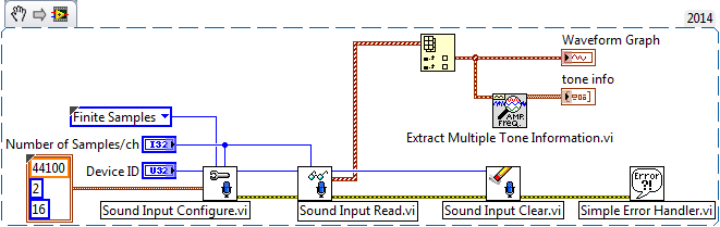
I have audio simple (level, THD, frequency) of the measures in LabVIEW with a sound card.
The audio signal is a sinusoidal 1 kHz analog single.
I know it's better to do it with a real audio Analyzer, but it would be a significant investment.
So, how can it be achieved with a standard of PC sound card? Thank you.I have a measurement of base (amplitude, frequency) with the following code:
-
Frequency of measurement with cDAQ NI 9402 chopper
Hello world
I'm new in the world of the cDAQ and try now just get a frequency of a TTL signal output chopper. I confirmed 23 Hz frequency on an oscilloscope. It's a nice clean 5V square wave, but when I try to measure the frequency in labview using a VI (dig frequency of continuous measurement) example, it comes to expire. Trying to look at the entrance of the signal in express shows signal an incompatible digital signal that is around 3 Hz and clearly the result of the port being interviewed for entry too rarely. The final objective is to get this work with the labview vi PLL is a detector lock in the amplifier, but first of all, I have to be able to measure and to read correctly this frequency.
My hardware is a cDAQ-9174 with a 9402 OR for use with the digital input. I don't know it's important, but the 9402 module is in slot 3 and I'm on channel 0. The software is labview 8.2 with DAQmx 9.1. Is there some timing issue material or the definition of I'm missing here? Any help is greatly appreciated, thank you!
Hi Skaboss,
Counters have multiple terminals (source, the door in and out), which map to separate on your NI 9402 PFI lines. For the measurement of the frequency, the default input terminal depends on the method of measurement (low frequency, high frequency, wide range). Here's the relevant section of the NOR-DAQmx help (which is on the Start Menu):
Connections of signals C series for counters
The following table lists the default input for various measures of meter terminals. You can use a different line of the PFI for one of the input terminals. To edit the entry PFI for a measurement, use channel NOR-DAQmx attributes/properties.
NEITHER 9402 and NI 9435 (4 channels)
Measure Ctr0 Ctr1 Ctr2 Ctr3 Number of edges Edges: PFI 0
County Executive: PFI 2Edges: PFI 3
Branch Count: PFI 1Edges: PFI 1
Branch Count: PFI 0Edges: PFI 2
County Executive: PFI 3Pulse width measurement PFI 1 PFI 2 PFI 3 PFI 0 Duration/frequency measurement (low frequencies with a meter) PFI 1 PFI 2 PFI 3 PFI 0 Measure of duration/frequency (frequency with two counters) PFI 0 PFI 3 PFI 1 PFI 2 Duration/frequency measurement (wide range with two counters) PFI 0 PFI 3 PFI 1 PFI 2 Measure semiperiod PFI 1 PFI 2 PFI 3 PFI 0 Measurement of two-Edge separation Departure: PFI 2
Stop: PFI 1Departure: PFI 1
Stop: PFI 2Departure: PFI 0
Stop: PFI 3Departure: PFI 3
Stop: PFI 0Measure of position A: PFI 0
B: PFI 2
Z: PFI 1A: PFI 3
B: PFI 1
Z: PFI 2A: PFI 1
B: PFI 0
Z: PFI 3A: PFI 2
B: PFI 3
Z: PFI 0Alternatively, you can override the default with the CI. Freq.Term channel property.
Brad
-
Vision of nor - strain measure with "tight".
Hello!
I'm trying to measure the diametral nothced specimens subjected to axial deformation strain. Due to the size of the samples, I use a CCD camera to capture the deformation. The device is set to capture 2 images per second, and so I get a huge batch of image files (~ 5000).
I want to use OR vision to process the images and found option 'clamp' suites my needs. However, when I want to execute a batch with my script, the process stops until I press OK in the "clamp" editing window. I want to be automated so that I can start the process, go home and get the results the next morning. The only result that I am interested in is the measured distance from the tool "clamp." If anyone has any idea how I can extract the data of each image in a text file (or similar), I would be very grateful.
Thank you
Jeem79
Specimen
If you know what works for you, the next step is quite easy. Set up the measure in Vision Assistant, then select tool-> batch. Select the directory that has all your images in it and tell him what you want to record. Once you have configured, click the run button. I would test it on a small number of images until you get what you want, then run on your set of images.
Bruce
-
Write to the file of measurement with a loop For using the value of the dynamic data attributes
I looked and looked, but couldn't find a solution for this.
I currently have 15 points of different data that I try to write in an Excel file. I have all combined in a table and lie with the function "write into a file position. However, the column names are always "Untitled", "Untitled 1" etc. I then used the function 'Set the Dynamic Data attributes'; but for this I have to do 15 different functions "set data dynamic attributes. It was suggested to use a loop with the function 'Set the Dynamic Data attributes' inside of her, but I can't find how do.
I have several arrays consisting of 15 different values for 'Signal Index' 'Name of Signal' and 'Unit', but also a unique 'get Date/Time In Seconds' related to 'Timestamp '. The problem is that the error I get when I try to connect the output with Scripture at the entrance to measure file:
The source type is dynamic data table 1 d. The type of sink is Dynamic Data.
How can I fix it? I have attached a picture of my installation; Sorry if this is gross (I'm new on this!). Thank you!
It will get rid of the error, but it is not quite correct. What you need to do after that is to click on the output or the tunnel entry and select 'replace with the shift register. In addition, the array of values that you have wired to the Signal Index is wrong. Arrays are 0 based. Just wire the iteration Terminal here. And, finally, take the size of the table and this connection to the N terminal are stupid. Don't wire nothing to this.
-
I'm having a problem to measure objects in Illustrator CC. The measure appears only in decimal, and when I try to change the value it changes all the object. Any unit of measurement, I chose, it comes up with anyone.
Everything appears as 1000.00000 (with many zeros after a point, as the picture below shows)

I tried to change something on the preferences, but nothing happened.
Could someone help me?
Weight of the race is pt 1000,0000
See the last message


Maybe you are looking for
-
SHIFT key no longer works correctly
Just after the update for Sierra, my shift key don't work as it should. I can use it to make caps, so I know there is nothing wrong with the keyboard, but I can't use it for shortcuts in the programs. For example, before I could hold shift and right-
-
digital digital indicator of coercion dot
Using the evaluation version of LabVIEW 2013 64-bit. I have a digital U32 digital indicator on the front panel. I'm passing a reference of it to a Subvi. The Subvi has a control that is the server VI-> generic class-> GObject-> control-> digital-> di
-
Floppy disks to install Windows have a related key or can I use the key with any disk?
Re Activation: I help people of disabnled. My blind customer has an OEM version completely crushed of XP and a damaged hard disk, so because there is no CD or the way to reinstall XP, I found an installation CD and, separately, a product code given t
-
Pavilion DV7 1020eo: upgrade CPU... how high... ?
Hello... I have a HP Pavilion DV7 1020eo with a AMD Turion 64 X 2 RM - 70 installed processor (2.0 ghz dual core socket s1g2) My question is what can I improve up to... ? Can I go to 2.8 ghz dual core or it can take in charge more than 3, 0GHz... ? I
-
I went to back up my system and he said (put in place backup) don't know why he should need that since I saved before. But I clicked on set up and he caimed to start. Then he threw an error that says... The appilication backup could not start due to