Digital acquisition of data streams
Hello
I tried (unsuccessfully) to acquire digital data of a sensor laboratory. The Guide from the manufacturer:
"When the excitement of voltage, DTC Decagon sensor makes a measurement. Three measurement values are passed for about 140 ms of excitement to the data logger as a character of flow series of ASCII. The series is 1200 asynchronous baud with 8 data bits, no parity and one stop bit. The voltage levels are 0-3, 6V and logical levels are (low active) TTL. The power must be removed and repeated his request for a new set of values to pass. The ASCII data stream contains three numbers separated by spaces. The first number is the depth of the water in mm, the second number is the temperature in degrees Celsius, with a resolution of 0.1 degree C, and the third number is the electrical conductivity in dS/m, with a resolution of 1 dS/m. A carriage return follows the three digits, then the character ' t "", which indicates that it is a sensor DTC, and then a control character, and finally a carriage return and supply line. ' "
My attached VI is a little dubious-it probably looks like something that someone used for analog signals may create. However, I was hoping it would be enough of a starting point for a more wise to work with LabVIEWer.
Thank you very much
Lacksagoo
The guide said in reality as a data acquisition card OR is the same as a data logger. I've never associated the two as being the same. What I think about a data logger is an autonomous instrument.
Looking for a more details in your original post, the voltage levels are not standard. You may need a shifter level or need to find a USB-RS232 adapter for TTL levels.
Tags: NI Software
Similar Questions
-
Acquisition of data from an external device that uses RS - 485
I am currently using a device cDAQ 9174. I'm trying to connect the cDAQ to an external source that communicates via a cable series RS-485. I spoke with several representatives of Lawbview and they told me that there is no direct way to talk on the chassis with the serial cable. I need to buy a USB-485 cable series and communicate in parallel in LabView. If I go directly through the cDAQ chassis, so why do I still need? And I'm lost as in how I communicate with an external source in Labview.
My second question.
I have a cRIO 9074. And, through a lot of research, I noticed that it seems much easier to use this device for this situation. My only problem is that I am new to LabVIEW and I think that working with the cRIO can be a little difficult for me at this stage. My question is, it would be easier to make the acquisition with the above configuration, or use the cRIO and spend a little extra time.
The application that I am trying to make is the following:
I have a RS-485 of the external source. Then, I want to broadcast the series of 2048 byte stream that is continuous in NEITHER and do review the serial data and assign a virtual indicator on a chart or display a message to tell me what will happen in the serial data stream.
cRIO is certainly more complicated to go only a USB-485 cable. cRIO is designed more for embedded applications, series No. You must also cDAQ in the equation. All you need is the following:
NEITHER USB - 485
http://sine.NI.com/NIPs/CDs/view/p/lang/en/NID/12845
Someone suggested a cDAQ to you for this application? cDAQ is a platform for flexible data acquisition for reading of the analog signals and digital bullies. If your data flow conforms to the RS-485 standard, you don't want cDAQ for this.
I have attached a sample program to help you get started. There are examples that are included when you install the NI-VISA driver that supports communication with LabVIEW series with LabVIEW. If you have installed NI-VISA it should appear on you NOR Finder example located in the main menu to help > examples find if you search for "serial".
-
Need a new acquisition of data USB multifunction device
Hello
Currently I use a PCIe - 6321 Multifunction DAQ hardware to control my stepper motor. I need to change the PCIe - 6321 and use the engine with a device for the acquisition of data USB multifunction bit PCIe - 6321. I'm not sure which USB model to select. Can I please get help about the choice of the right MIO USB data acquisition device that works similar to the PCIe - 6321.
Thank you
Bharath J S
The 6212 differs from the 6321 somewhat on the digital side, which probably you use to control your stepper motor. For example, it was only software DIO timed tasks and has only 2 counters with a set of features (e.g. no output meter in the buffer).
Best regards
-
Restarting a task for the acquisition of data inside a For loop
Hello
I need iterate through my acquisition of data. Currently, I'm doing this through the creation, implementation and tasks for the acquisition of data inside a loop For which is iterated according to the needs of compensation. Unfortunately, the creation of these DAQ tasks slow down my code.
I would like to be able to create the tasks outside the loop, pass them in and revive the tasks at the beginning of each iteration. Is there an easy way to do this?
Otherwise, is there a way to make the standard DAQmx digital startup trigger trigger several times (so that it starts each pulse data acquisition in a long pulse rather than just the first pulse train)?
Thank you!
-Evan
I whent before and created this example for you (and many others.)
-
Acquisition of data and filtering on FPGA
Hi all
I have trouble to design a FPGA program for acquisition of data and filtering.
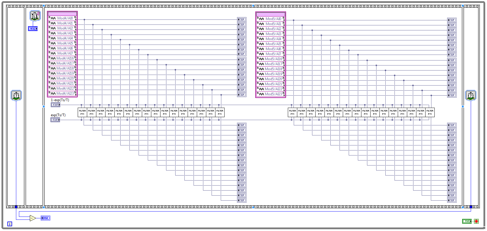
I have two NOR 9205 modules configured to work in terminal mode of DIFF, i.e. There are 32 entries this program must read every Ts seconds. (Ts is the time discretization, i.e. during the period of loop)
With respect to the digital filter, I implemented a possible simple filter with transfer function G (s) = 1 /(1+sT), which is part of the field of discrete-time equal to y (k) = a * u (k - 1) + b * y (k-1), where u is the original signal, and there is filtered signal. The coefficients a and b are equal to: a = 1-exp(-Ts/T), b = exp(-Ts/T), and T is the time constant of the filter (usually T > 5 * Ts).
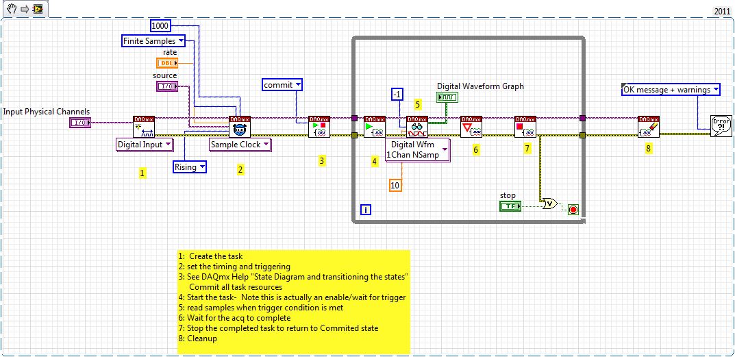
The implementation of main program for the acquisition of data and filtering are:
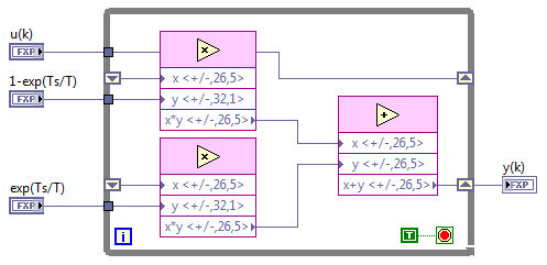
This application is for the digital filter:
However, the problem is that this program cannot take the FPGA resources on cRIO-9114, and Yes, I tried to define the criteria of compilation for the area. I also tried to implement the multipliers in digital filter as lut and DSP, unfortunately without a bit of luck.
Because I don't have that much experience in programming of FPGA, someone has any suggestions how to improve this code to adapt existing FPGA resources?
Best regards
Marko.
Hey Norbert_B,
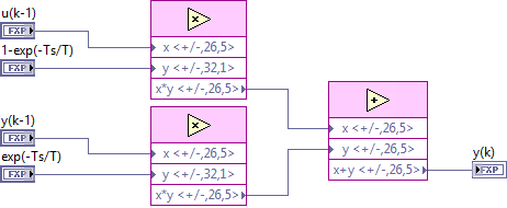
I managed to solve the problem. First, I changed the reentrancy of Preallocated incoming execution clone to not reentrant execution. As no reentrant VIs have States, I had to use the node of the feedback to the main VI to get u(k-1) and y(k-1). Another important thing is to choose Ignore FPGA reset method in the node of the properties of FPGA implementationfeedback, since in this case, the feedback node uses less resources.
Here is the new main program VI:
And here's the 'filter' VI:
Thanks for the help!
Best regards
Marko.
-
How to block a number of cardboard/acquisition of data to a particular program?
Is it possible to "connect" a DAQ card serial number with a Labview design/program?
For example, PCI-6601 is a serial number 12345 and I write a program (called ProgramABCD) to the acquisition of data, I want to "tie" / "bind" 12345 and ProgramABCD together, so that ProgramABCD will not work on an another PCI-6601 (unless I have change the serial number corresponding to ProgramABCD for the new PCI-6601).
Thank you.
Hi celine,.
You could read the serial number of the device programmatically using a node property and then based on that, decide whether to terminate or continue the program. See this link: http://digital.ni.com/public.nsf/allkb/92F3F7C79579FA238625718700764F9D?OpenDocument
However, if this will be distributed to the end user as a .VI file not an executable, then the end user could always go into the code and change/modify it so that it can use different devices with it.
-
Read for the acquisition of data entries are overwritten
Hey there
I have a Daq reading input in a spreadsheet file
Data acquisition was told that one is supposed to have some time a loop around it and I cannot get it to run without one, so good
But my main problem is that it means that it replaces my written file each time that the loop repeats
He also asked me to choose the file to write in several times
How would I go about fixing this?
Thank you
Yes, you can convert digital to the chain, check the attached VI. I recommend you to go through the basic materials of LabVIEW and also play with example of NEITHER which comes with LabVIEW. Remember not to use the attached example and the acquisition of data, always use separate loops.
-
Acquisition of data using C++ and cRIO-9066
Hello!
I want to write a C++ application that would make the acquisition of data from modules installed in the cRIO-9066 chassis and this application should work without LabView. How can I do? This chassis connect to my PC using NI-DAQmx? Is this possible?
Hi aanodin,
When you use a device that uses our architecture of RIO, it is usually best to use LabVIEW to develop your application. In this way, you can also program the FPGA with LabVIEW FPGA module and makes programming much easier real-time processor. In fact, your model of cRIO is officially supported by our LabVIEW programming language, as seen on page 4 of the Manual: (http://www.ni.com/pdf/manuals/376186a.pdf).
Due to the FPGA interface, you cannot use DAQmx with cRIO. I hope this helps.
-
Remove the first 5 blocks in a data stream
Hi all
I have a problem to remove the first 5 blocks in the data stream. My sampling rate is 1 s, block size is 1 and the entrance is the module «the ddf file read»
I use the following modules for an average analysis 30 years running.
[read the folder]---> [Formule1] -> [set variable] -> [formula2]
| ^
--> [time]-|
module parameter
====== =========
delay of 30
Formula1 ${var_1} + in (0) - in (1)
the value of variable ${var_1}
Formula2 in (0) / 30
This configuration is used for channels 13 and one of these channels is used for purposes of triggering. Due to the nature of the variable defined and read in the underlinedmodules, the trigger sequence is delayed for 2 sec. Since I used the trigger to collect the last returns average of each channel, it is now mixed with 2 sec for the next round.
My question is: is there a way to reduce say 5 blocks of data from the stream? Please help and have a nice day

Look at the SEPARATE module in the Group of data reduction.
It allows you to set up an initial leap, then a current break.
To do this, you want to jump 5 blocks once, does through go zero blocks... who spends the first five and then release all the data blocks of subsequence.
-
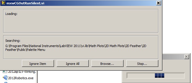
Acquisition of data NOR usb 6008: a strange problem: mxwcgoutrunsilent.VI is not respected
Expensive OR
Today, I bought an acquisition of data NOR usb 6008
and I'm using labview in 2011
the problem is appear when after I end the process of configuration of the i/o data acquisition Wizardthe following image shows the mxwcgoutrunsilent.VI is ignored and an error has occurred
someone can help provide this VI for me
What is the complete labview modules can also so I could do a real time data acquisition
Best regards
mangood,
You received an error code? If so, what is it? What version of NOR-DAQmx driver you have installed? It seems your driver potentially incorrectly installed, and you may need to reinstall the driver.
Here is the link to the latest version of the NOR-DAQmx driver: http://www.ni.com/download/ni-daqmx-9.8/4297/en/
-
We send 5v data acquisition using a voltage generator. Hook us it up to a voltmeter and see 5V. When connect us the generator voltage to a valve "normally open" parker, the voltmeter indicates .14V. It seems that when we connect the two sons of the valve for the voltage generator, the son act as pattern. We want to control the voltage flowing to tap through Labview. We checked the wires to the valve and they work very well, because if we send a constant 5V since the acquisition of data and put ashore, she, the voltmeter indicates 5V. Someone knows why the son act as pattern and low blood to .14V?
nsatpute wrote:
Our data acquisition is NI USB-6259. The valve requires only a 5V max and our DAQ provides up to 5V. However, after connecting the valve to the acquisition of data, the grave tension to almost 0. We start from the principle that the son somehow act as the reason, but we are not sure if this is the case.
The question here is not how much voltage the valve wants, it's the current needs of the valve. The 6259 can put only 5mA via an analog output. Your very likely tap needs much more than that. If you need to add in an amplifier circuit that can supply more current to operate your faucet.
-
Looking for a way to mount an acquisition of data USB-6008
Anyone has a suggestion for an acquisition of data USB-6008 mounted on a Panel. I use it for a system where it should not be loose. I have a few ideas, but hope that someone smarter already has a good solution.
Thank you
It is not a robust application, but the box will be moved and I don't want it put in the open air. I simply put a velcro pad on the back and the atttaching in this way. Should be all I need.
-
merger acquisition of data to read input data 2 or several at once
Hi all
I'm using or usb-6009 more then 2 incoming signals.
the problem is that I can't read 2 signals at the same time. 1 my daq assistance will be apeared to be error.
so, how can I set the .vi (attached) so that he could read 1 more signal since the acquisition of data?
I also tried to separate daq support but error. I also try to merge the two signals with a different port (a1 and a0)
can anyone help?
Thnx for the reply
Frankly, I went through all the tutorials and looked for answers in the forum and the conclusions I have difficulties to understand the technical language... I have been looking for everywhere labview users and found someone who could guide me carefully... im have desperately need guidance... not to give up hope trying to find the answer, but a sort of feedback that is giving advice that you need to take the driver's seat... FYI... I take the driver's seat... that look like a real Nubian now needs help...
is there any order step by step so that I could add channels more 1 1 daq help?... I've done it before, but it occurs.
for example, I want to create channel 1 to read the value of the resistance and channel 2 for playback of tension... but what happened when I create more than 2 channels, it is be will configure this channel only 1 located in the block diagram... both channal will give only data for the value of the resistance.
Sorry for my broken English.
-
Operating system: Windows XP
Hardware: PCI 6259
Terminals used: PFI0 and PFI2
Counters used: Ctr0 and Ctr1
IM developing an application for the acquisition of data where timed loop synchronization source comes from my PFI2 (using the string A of an encoder). IM basically trying to acquire data based on the number of ticks from my encoder. For the synchronization source, I use counter 1 to capture the rising edge and have the loop time-acquisition of data. At the same time, Im using the counter 0 to count the number of rising edges so I know exactly in what tick data was acquired. PFI0 and PFI2 are connect to channel A of the encoder.
Questions:
Timed loop acquires data at each tick, because when I discover the data (text) file is missing count of my encoder value. Is it because there is a limitation on the Windows operating system? I used a noculars to measure the frequency at the maximum rotation of the channel encoder and 6,757 kHz. All solutions?
Also, is there anyway I can route the source channel internally an encoder to generate synchronization source instead of using another counter? I have attached my VI.
Hello
All the samples that you acquire will be read by LabVIEW in a sequential manner. Figure 4-21 on the M-series on page 80 (4-34) shows that you will acquire all the samples you request all channels that you enjoy in sequentially.
-
Difficulty to read the instrument of series and acquisition of data simultaneously.
Greetings,
I have some trouble getting my VI read from my data acquisition and instrument of the series at the same time. If I run the Subvi simultaneously (i.e. subANG runs in a window and subVEL is running in a second window) both return the correct values and behave as I expect. However, if I call the Subvi in a society mother VI and try to run them both in the same loop structure subANG gets stuck and won't be reprobed with a signal change.
I also tried to use a stacked sequence or plate to separate the execution of subVEL and subANG, but I still get no response to subANG.
The point is is that, if I run Parent.VI in a single window and then creates a copy of subANG (call it '--copy' or other) and run it in a second window, Parent.VI behaves properly and will update the readings as they appear in '--copy '.
I enclose 3 files.
(1) subANG.VI - this bed an an inclinometer RS232 signal. The signal is refreshed every 10ms or more.
(2) subVEL.VI - this bed raw tension of a channel on the acquisition of data, calculates the average then that converts into a pressure difference and finally a speed based on the pressure and temperature inputs.
(3) ParentVI.VI - they simply call and displays the Subvi
My guess is that it's a buffer problem, but I am confused. Someone out there in Labview Earth knows why this might be happening? Suggestions welcom.
It is not an instrument of series. It is a UEI PowerDAq with their typical A/D and the cable.
I found away to make it work by placing subANG and subVEL in some time different loops side by side in ParentVI.

Maybe you are looking for
-
Contacts E-mail only automatically add to Contacts from the Exchange (Office 365)
Don't know if anyone else has this annoying problem... Something is create new E-mail contacts only in my 'Exchange' directory of contacts OSX. They do not appear in the 'Contacts' Exchange directory (I use Office 365 for enterprises). They seem to h
-
How to remove my ifone id icloud
my iphone has the ID of a person. and also the icloud IDS. How can I delete / remove this ID. Note: I don't have a password of this ID I have buy the iphone from the local market, which have the ID of a person
-
Swype is missing from my device?
When I go to settings/lang + keyboard and click input method only multi touch keyboard is it listed?
-
My s5280t (HP Pavilion Slimline Desktop, purchased late 2009) suddenly "died" this morning. not sure what exactly is wrong with it... I have run most of the time, which suggests (surprisingly for me) in the owner's manual. each time a program will ch
-
I was not able to download the service pack SP3. The update system worked OK until I did the reinstall (simply by using the hidden OEM partition system) but the XP SP2 is perfectly legitimate and as that provided with the Acer laptop.