Digital and analog inputs simultaneously - NI USB-6009 and NI USB-6212 - ANSI C
Hello
I'm reading at all times and at the same time analog and digital inputs. Digital and analog samples must be sampled at the same clock and acquisition should be started (triggered?) at the same time (I don't want, after some time, analog reception more digital samples - the opposite is also true).
I found an example (in C source code) "National Instruments\NI-DAQ\Examples\DAQmx ANSI C\Synchronization\Multi-Function\ContAI-Read dig Chan" and tried to run with two USB cards: NI USB-6009 and NI USB-6212. Unfortunately, the two results by mistake, as described below:
DAQmx error: the requested value is not supported for this property value.
Property: DAQmx_SampTimingType
You asked: DAQmx_Val_SampClk
You can select: DAQmx_Val_OnDemand
Task name: _unnamedTask<1>
State code:-200077
End of the program, press the Enter key to exit
-Is it possible sync analog and digital acquisition in the paintings?
-If so, how?
Thank you
Hello tcbusatta,
Two of these modules, USB = 6008 and USB-6212, support only timed software inputs and digital outputs. This means that you cannot define material timing (like finished sampling or continuous) for these modules. Digital lines can be retrieved or written once to each call DAQmx read.
This means that you will not be able to get any type of synchronization tight between the analogue and digital channels. You will need a Board such as the NI USB-6341 in order to synchronize the AI and DI closely.
Tags: NI Hardware
Similar Questions
-
Generation and acquisition of analog signals simultaneously on USB-6212
Hello, I am novice programmer DAQ trying to create (what I think is) something very simple.
I use a box NI USB-6212 and LabVIEW 8.5 is trying to generate a pulse train analog while recording a simultaneous analog input.
My first question is, is it possible?
Since I'm new to this, I use the DAQ assistant in LabVIEW. I can acquire a signal, I can also generate the desired signal, but I can't seem to operate simultaneously.
I have been successful in obtaining my program to work with both USB-6212, but I have to be able to do this with a single.
I have attached the block diagram and vi, I hope that's easy to answer the question, even if my research so far has left me empty handed.
Any help would be greatly appreciated!
Jon L
Hi Jon,
Well, first of all welcome to the DAQ programming! I took a peek at your code and published it with a device simulation very well, so I ran with the PCI 6251 card in my computer and he did not also get errors. Could you post the error code you get?
If I could figure out what is your error, I would say you encounter errors of buffer because it is too much overhead in the DAQ to wizards in the face of data rates. My suggestion would be to use the example called "Multi-Function Synch AI - AO.vi. This program can be found in the Finder for example of NOR (see Help"find examples in LabVIEW). "" It appears in the input and output material"DAQmx ' synchronization ' Multi-Function.
Can you give that a try and let me know how it goes? Thank you!
-
How to read 3 analog inputs simultaneously with 6070E?
Hello
I wanted to read 3 analog signals simultaneously using cards of acquiring data NI PXI-6070E and Labview 2010.
I can with success read and record the 1 signal (which you can see in the attachment), but do not know and can not find examples on how to read 3 signals simultaneously. Any help, especially a simple example would be great.
Thank you!
Just click on = pull down from the constant physical channel, select Browse and shift-click or Ctl-click here to add other channels. You can also type in new channels with the ai0 syntax: 2 for three continuous channels for example.
-
How to use 1-channel analog input for start/stop aquire sample second channel input analog?
I have a little problem. I've just been programming in labview for 2 weeks.
I'm trying to figure out how to use my channel of analog input on the USB-6009 case for start/stop (reference trigger and start) presented to the second analog input channel samples.
I need the first analog input string to operate continuously and control sampling on the second. When the second channel will start sampling program brings a new graph each time and saves it (I have all this that figure out).
How can I configure the trigger so the lance program presented in for the second channel when the 1 channel reached above 2V (e.g.) and stop when it falls below 2V.
I use a pressure force sensor on the first channel that gives me straight (up to) 5 V when it is pressed and nothing when it is not...

Thank you.
Grand... Thanks for the information!
But can't I then make a 1 channel instead and wait until that meat of the max element value?
-
Using the DAQ USB-6009 meter and an analog input voltage at the same time.
Hello
Currently, I'm reading the two channels of voltage with the USB-6009. It happens that one of the channels is the output of a digital coder, and it would be much easier to use it directly to the PFIO entry that is defined as a counter. The problem I am facing right now, it's that I can't use the DAQ Assistant to use the analog voltage to a channel and the digital channel counter at the same time. Once I put the DAQ Assistant to read the input from analogue voltage, I won't be able to add analog inputs. And as I put the DAQ Assistant to use the PFIO as a counter, I can add more entries to read analog voltage is.
I wonder if it is possible to solve this problem using the lower level data blocks? Another solution would be to read two channels in analog input voltage and that the use of Matlab to process data resulting from it, since I was not able to do the counting to work simultaneously with the acquisition in Labview to impulses.
Hope you guys can help out me.
Thanks in advance.
Using a simple wizard of DAQ is incorrect. You need one to acquire analog inputs and one for the meter.
-
6009 outputs digital and analog input synchronization
Hello
I work in a program NI 6009. I want to leds by car with outputs digital NI 6009. For example, leads first will be on until what 200 micro seconds then second led will be on up to 200 micro seconds, and then first of all led will be on up to 200 micro seconds. I'll take led with photodedector signals and connect analog output photodedector input NI 6009. I want to synchronize the outputs digital and analog input and separate the first and second led signals the analog input for NI 6009 channel. How can you do with NI 6009? Please ADV
You can not do with the USB-6009 case. Its outputs digital are software with a maximum speed of slightly more than 100 samples per second. The outputs can produce 200 microsecond pulses and cannot be synchronized with the analog input.
You need a device with outputs digital hardware timed or counters that can produce a pulse outputs.
You can synchronize a bit digital output and analog input recording signal on an additional channel to HAVE. Will allow you to see the photodetector and LED the drive with the same schedule and such resolution as described by the sampling rate I. The maximum sampling frequency of AI on the USB-6009 case is 48 kHz that is shared by all channels. If you have two lights to led and photodetector two signals maximum sampling rate would be 48 kHz/4 = 6 kHz which is barely fast enough for your 200 US signals. For more than 4 channels, it won't be fast enough.
I suggest a simple oscillator circuit building and use it to clock a flip flop. This will give you alternating signals to drive the LEDs. You can use a line to reset the flip flop to give you control without the need for high speed.
Lynn
-
Digital and analog simultaneous inter channel delay
I need to a simultaneous analog input 1 channel and 1 entered digital who intend to make possible acquisition of maximum speed. Of course I expect no delay channel inter if the two entries on the edge of clock sample even sampling. But this example shows unexpected behavior. Restart acquisition regularly shows different delays inter channel. I hope there is someone there to help out me. See the included example.
I asked the support of National Instruments and they came with an adequate solution.
Time t (0) stamp in the waveform is NOT the start time of the acquisition but it is the time the buffer is read.
To demonstrate this applies the same "pulse train" to the two channels and t (0) all forms of wave at the same time of departure. Observe that the edges of both signals match exactly. Because a single channel is a digital input, we make the logic of levels of tension into account.
Thanks to Henk Talsma
National Instruments
Engineering applications -
With the NI USB-6009 analog input lag
Hello
I try to acquire analog signals with NI USB 6009 using LabVIEW. (The signal is 50 Hz of the functional generator).
However, the acquired singnal has dynamic splitters, which is NOT observed by my oscilloscope.
I have no idea why this phase shift occurs.
Any information is welcome. Thank you for reading.
An image file will not help. Post your real VI. If Firefox does not work, use explore or Chrome to fix your VI (s)!
You have here a Subvi, I don't see what's inside and how it is configured. In addition, this while loop is ridiculous: there is no button to stop him running. Never use the red button to abandon for a normal shutdown of a VI!
Why you have configured NChan NSample? Measure a unique signal, Yes? For example, use 1 channel only.
Edit: why do not you play first with an example given, delivered with LabVIEW?
Your LabVIEW, go to the Help menu--> find--> material and output examples--> DAQmx--> entry--> and open 'Input.VI - constant tension!
This VI allows to enjoy your analog signal.
-
Hallo,
I use the following system:
- OR PXI-1044 with controller NI PXI-8109
- OR PXI-2564 switch module to turn on the monitor of my test device
- Data acquisition multifunction NI PXI-6259 to measure the signal that responded to the questionnaire jump
The two cards are the same - PXI trigger bus. For both, PXI-2564 and PXI-6259 I use DAQmx to set the reading and writing of the channels.
Now, I want to measure the time between the digital output, my unit turns and the analog input, which measures the response of my system.
I can't do work by myself, please help me!
I thank Ludwig.
Hi Ludwig,.
If you can't give us any VI we have difficulties with to help you.
Because I Donat knowledge how your program is mounted it is not easy to know where you should enter signals.
Here's a question similar to yours:
http://forums.NI.com/T5/LabVIEW/best-way-to-measure-time/TD-p/178704
and 2 external links:
http://www.ehow.com/how_8698983_measure-time-LabVIEW.html
http://objectmix.com/LabVIEW/385152-how-can-i-use-LabVIEW-measure-time-between-analog-pulses.html
-
How to synchronize the analog input and the output of two different USB data acquisition boards
Hi all
I have two tips very different USB NI USB 6008 case, which I use to acquire the data (analog input) and a USB of NI 9263 is a output analog only site I use to route a signal (in this case a square pulse). The reason why I use the outputs analog 6008 is because I need to deliver negative tension and need the full +/-10 v range.
Looking at similar positions, I'm pretty sure that I can't use an external trigger or a common clock, I also tried to use the timed synchronization of the structures but no cigar.
I'm including a quick vi I whipped showing how the jitters because of the lack of synchronization signal. The OD of the 9263 connects to AI in the 6008 in this example.
I talked to a specialist in the phone and tols me that's not possible.

-
6143 - PCI or PCI-6133: simultaneous reading of analog, digital, and counter
Hello Board,
I want to use a PCI-6143 or 6133 to acquire permanently synchronized values ports analog, digital, and counter on the same device.
I use vb.net to build an application that reads the values of the device buffer and stores them in lists for later use.
By reading some other threads I discovered, that all the S series devices are able to use a source of material for the release of the digital ports.
Here are two among them? What meter ports, they suffer from the same problem?
Software trigger is no option because the sampling rate must be accurate.
Thanks in advance for the answers,
M.B.
Hi M.B.
6143 does not support Correlated DIO (i.e. clocked by the hardware), the 6133 (see-> digital I/o--> Timing). As a result, synchronized doing of entry works with the latter. Acquisition of meter in the buffer is available on both devices. The 6133 also authorizes analog and digital triggering.
To synchronize these tasks, you need to export a clock signal (sample clock HAVE for example) and take to the DIOs and counters for an acquisition in the buffer. An example for synchronization of AI and DI is given once you install the DAQmx driver in the
Please let me know if you need more specific information.
Kind regards
Peter
-
analog input on USB-6009 - what potentiometer to use for this test?
Hello, I am referring to this video
http://www.YouTube.com/watch?v=rSNRG_Ddl1s
What is the resistance (ohm) the potentiometer used in the film?
Thank you
Luke
They know the author of video ...
Since it is connected to the output of 5V to the DAQ card, you don't want to use too low of a low value.
A pot more of 500 ohm must work safely. Exact value is not critical for this demonstration. Rear wiper terminal must be connected to the analog input, the other two legs go 5Vout and GND.
-AK2DM
-
USB-6212: software problem timed task of analog input
Hi all
I have unexpected behavior using a USB-6212.
The code example shows that when I run in sequence two analog DAQmx to task, material entry first a timed, the second software timed, it happens that the first readings of data are all wrong and have the same value for all channels.
The labour code is the following:
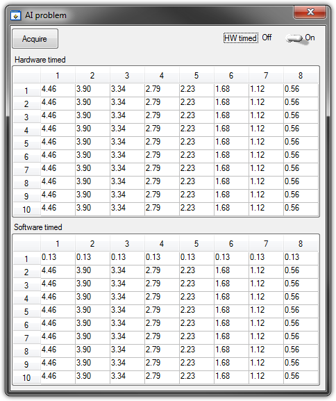
   GetCtrlVal(panelHandle, PANEL_HW, &Switch);

    if (Switch) {
//
// First Task: read 10 rows of values with hardware timing
//
        DAQmxCreateTask("", &htAI);
        DAQmxCreateAIVoltageChan (htAI, MX_DEV_AI, "", DAQmx_Val_NRSE, -10.0, 10.0, DAQmx_Val_Volts, "");
        DAQmxCfgSampClkTiming(htAI,"", SAMPLE_RATE, DAQmx_Val_Rising, DAQmx_Val_ContSamps, 1000);
        DAQmxRegisterEveryNSamplesEvent (htAI, DAQmx_Val_Acquired_Into_Buffer, SAMPLE_RATE, 0, RefreshCB, NULL);
        DAQmxStartTask(htAI);
            Delay(1.0);

        DAQmxStopTask(htAI);
        DAQmxClearTask(htAI);
    }
//
// Second Task:read 10 rows of values with software timing
//
    DAQmxCreateTask("", &htAI);
        DAQmxCreateAIVoltageChan(htAI, MX_DEV_AI, "", DAQmx_Val_NRSE, -10.0, 10.0, DAQmx_Val_Volts, "");
        DAQmxStartTask(htAI);

    for (i=1; i<=10; i++) {
        DAQmxReadAnalogF64(htAI, 1.0, 10.0, DAQmx_Val_GroupByChannel, AcqVoltRow, HW_AI_CHANNELS, &read, 0);
        SetTableCellRangeVals (panelHandle,PANEL_SOFT, MakeRect(i, 1, 1, HW_AI_CHANNELS), AcqVoltRow, VAL_ROW_MAJOR);
        Delay(0.1);
    }
    DAQmxStopTask(htAI);
    DAQmxClearTask(htAI);
A picture is worth a thousand words: analog inputs have been connected to a network of resistance have known values.
The upper table contains timed material acquisitions, the lower the software timed readings... as you can see it the first line is the set of values of 0.13, totally wrong
If the task of timed acquisition of software runs without the earlier (in my demo, that this can be achieved by the switch at the top right), the readings are correct!
Y at - it something I am doing wrong?
I also tried to run the program on USB-6009, but it seems to work properly.
[LabWindows/CVI 2010 SP1 - driver OR-DAQmx 9.4 - Windows 7 x 64]
This problem was corrected by NOR-DAQmx 9.5
324044 NOR USB-621 x task HAVE request returns incorrect data after erasing a task HAVE stamped
-
How to write constantly to analog output and read from analog inputs
Hi all -
I had a question about writing continuously to analog output reading simultaneously an analog input.
It's my first time to post a message to the community, so please let me know if I made mistakes.
I use Labview 2011 with a NEITHER-DAQ USB 6215.
I'm looking to generate a waveform and write it continuously in an analog output. It is then connected to an entry on the acquisition of data, where I am trying to sample the analog signal. (I realize, there is a system of trivial, but I'm hoping to build on it once I have run).
The task of reading from the analog input works fine, as I tested it in several other cases. I have a problem writing to the analog output.
For this task, I tried to follow the "Gen Cont Wfm Clck Int' VI to generate the wave form and start the task. I then try to write to the output of the analog timed loop. However, it does not seem to transmit a signal and doesn't give me any errors.
I have attached the VI but also a screenshot.
Please let me know if anyone has any ideas. I would really appreciate the help!
Thank you
Peter Borgstrom
We will review your tasks one at a time. First of all, the task of generation/Analog output Waveform. Generate you a waveform (I'm unsure of your VI if it is a fixed waveform or not) and send it to a defined output function to produce a waveform continuously, using N-channel and samples of N (where you set not these previously). You should not put this inside has timed loop, as the DAQ hardware has its own clock - if you simply put it in a while loop (with a stop to break out of the loop), the loop will call the function for the first points of N, wait until all N have been taken out, then call it again to another N points (up to what you press Stop).
Now, suppose that you have the output connected to a load voltage (say a decent resistance). You can wire the input terminals of your A/D converter through the same load and set up a similar analog input loop, running in parallel (i.e. in its own independent of the OD loop, while loop). You pourriez start together (with, say, a merged error since the initialization code line loops HAVE and AO become lines of error in "loops of sampling" described above), but you might want to delay loop (a little) the AI so that the OD has a chance to set the voltage before the bed.
I hope this helps.
BS
-
Several analog inputs seem to change any of the other (details DAQ: 2120 BNC and 6062E)
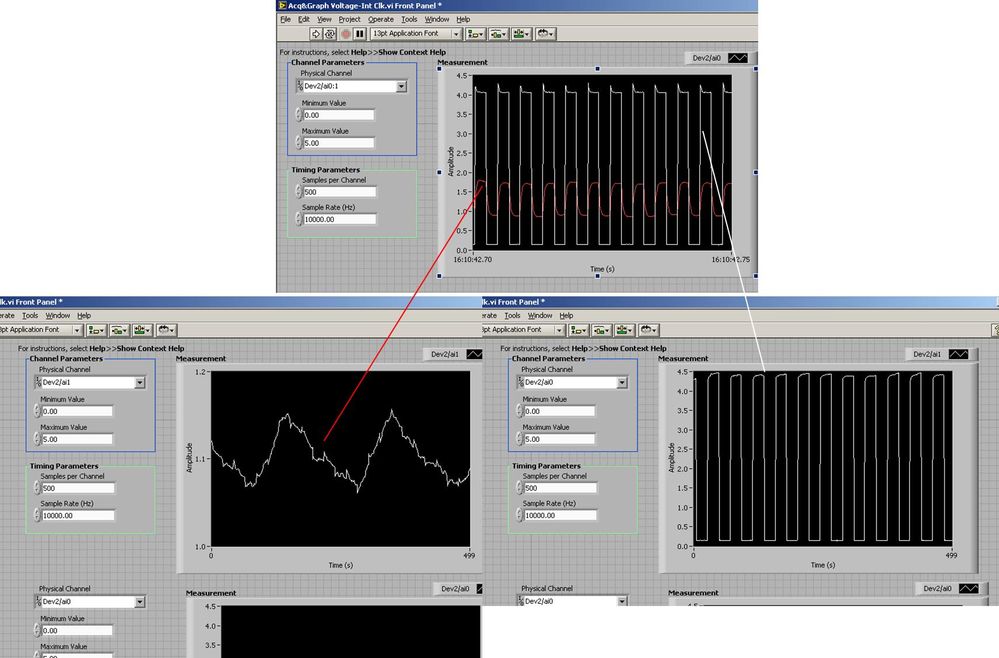
I use the BNC 2120 DAQ board connected to the data acquisition card 6062E to record two analog inputs. An entry is connected to ai0 and the other at ai1. Example vi: "Acq & graph int clk tension" has been used to measure the two entries with the value read NChan NSamp vi (channels being dev2 / ai0:1). The output is the top graph in the image. However, this seemed a bit strange to me that one of them should be modulating with a different frequency. When I record both entered individually (two in low pictures) they are indeed different since the entries shown in the top graph.

Why this would be the case, and how can I overcome this to measure the real signals?
Thank you!
The E series card takes the samples as soon as possible. Thus, for example,.
If you have 16 analog input channels but you only read of
channel 0 and 1, the map will show the channels 0 and 1 right
After and then wait 14 'ticks '. What's that little run-in
the origin of the afterglow.
I think you can get the card to wait a certain
number of ticks with a property node. I have attached a screenshot. You
can find the property node in the palette of functions >
Measurement of e/s > NOR-DAQmx > node Timing. Expand it
Property node so there's two entrances. The properties are in
Left click on the node and going more > converted >
Its properties delay units and sampling clock delay and delay that
you want.If the phase is important so the above is not the best
the option because it causes a delay in phase. So, if you need true simultaneous
sampling, then you will need different hardware. The S series is everything
simultaneous sampling.Or, rather than the Delay property and delay units, try the Rate property
find more > converted > rate.If this is not
work either, you can move the second signal source to, say, AI8 and
Connect everyone to the ground. Readings for these, but just do not take into account
the data. In this way the ADC will sag to the ground at the time where that can happen
the second string in the way so that you should not see this frequency
ghosting on the other channel.
Maybe you are looking for
-
my hp 8500 has will travel with the hp scanning program, and save, but I cannot open the document
Using HP scanning in my HP program, I can scan a document with my HP Officejet Pro 8500 a Premium P/F/s scanning HP program shows me a preview so I know that he has analyzed correctly, and I can save the document as I want to, but when I try to open
-
Vista SP 2 and DFS = logon failure: unknown username or bad password.
After updated a few customers today to this service pack level, they could no longer reach the namespace which worked just. I have a mix of XP SP3, Vista SP1, SP2 and Windows 7 clients. All clients are x 86 with the exception of the Win 7. This er
-
Counterfeiting of Windows operating system
I got a built-in computer, with what I believe to be a fake Windows operating system, can I download the one I have on this subject? How can I fix it?
-
To start my computer upward as usual and takes me to open a session. I connect and my background appears, however my desktop icons, start menu and taskbar DO NOT appear. I can still access the Task Manager and command prompt, but when I try to use a
-
My question relates to the use of Windows Vista Edition backup Home Premium 32-bit
I use Windows Vista Home Premium 32-bit backup to create a backup on an external hard drive files. the disk is almost full, I noticed the backup appears to create a new set of files each time that it will consume a considerable amount of space. Is i