USB-6212: software problem timed task of analog input
Hi all
I have unexpected behavior using a USB-6212.
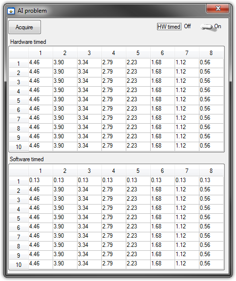
The code example shows that when I run in sequence two analog DAQmx to task, material entry first a timed, the second software timed, it happens that the first readings of data are all wrong and have the same value for all channels.
The labour code is the following:
   GetCtrlVal(panelHandle, PANEL_HW, &Switch);

    if (Switch) {
//
// First Task: read 10 rows of values with hardware timing
//
        DAQmxCreateTask("", &htAI);
        DAQmxCreateAIVoltageChan (htAI, MX_DEV_AI, "", DAQmx_Val_NRSE, -10.0, 10.0, DAQmx_Val_Volts, "");
        DAQmxCfgSampClkTiming(htAI,"", SAMPLE_RATE, DAQmx_Val_Rising, DAQmx_Val_ContSamps, 1000);
        DAQmxRegisterEveryNSamplesEvent (htAI, DAQmx_Val_Acquired_Into_Buffer, SAMPLE_RATE, 0, RefreshCB, NULL);
        DAQmxStartTask(htAI);
            Delay(1.0);

        DAQmxStopTask(htAI);
        DAQmxClearTask(htAI);
    }
//
// Second Task:read 10 rows of values with software timing
//
    DAQmxCreateTask("", &htAI);
        DAQmxCreateAIVoltageChan(htAI, MX_DEV_AI, "", DAQmx_Val_NRSE, -10.0, 10.0, DAQmx_Val_Volts, "");
        DAQmxStartTask(htAI);

    for (i=1; i<=10; i++) {
        DAQmxReadAnalogF64(htAI, 1.0, 10.0, DAQmx_Val_GroupByChannel, AcqVoltRow, HW_AI_CHANNELS, &read, 0);
        SetTableCellRangeVals (panelHandle,PANEL_SOFT, MakeRect(i, 1, 1, HW_AI_CHANNELS), AcqVoltRow, VAL_ROW_MAJOR);
        Delay(0.1);
    }
    DAQmxStopTask(htAI);
    DAQmxClearTask(htAI);
A picture is worth a thousand words: analog inputs have been connected to a network of resistance have known values.
The upper table contains timed material acquisitions, the lower the software timed readings... as you can see it the first line is the set of values of 0.13, totally wrong
If the task of timed acquisition of software runs without the earlier (in my demo, that this can be achieved by the switch at the top right), the readings are correct!
Y at - it something I am doing wrong?
I also tried to run the program on USB-6009, but it seems to work properly.
[LabWindows/CVI 2010 SP1 - driver OR-DAQmx 9.4 - Windows 7 x 64]
This problem was corrected by NOR-DAQmx 9.5
324044 NOR USB-621 x task HAVE request returns incorrect data after erasing a task HAVE stamped
Tags: NI Hardware
Similar Questions
-
USB-6009 software simultaneous timed output analog
Ladies and gentlemen,
I worked on a LabVIEW interface to a potentiostat I designed and built. I'm not very experienced with LabVIEW, but do they have experience with a variety of other languages (I had originally intend to use an FPGA for this, but he has been asked to write a LabVIEW VI first) programming.
The goal:
I want to output a voltage (initially consisting of ramps) signal and measure the voltage with an operational amplifier configured as an ammeter of feedback (using resistance feedback and voltage value to calculate current) connected to an electrochemical cell. The resistance of feedback is selected by using an automatic selection function (although I wrote a version prior to manual control) as TTL values using the DAQ Assistant to select relevant MUX channel outputs. I then try to save the data in a spreadsheet.
The problem:
I use an acquisition of data USB-6009, and I know that there is a hardware clock. Read all about him seemed obvious, the best way to the waveform of the output voltage used DAQmx package to define a function of writing in a loop that is clocked by the software. The problem I have is that I can't synchronize the output to the input with reliability and I have also some errors related to resources DAQ being reserved (error 50103). I think the way to solve this would be to convert every equivalent DAQmx DAQ Assistant and try to group their execution - this is where I fall. I tried to write a simple VI who shared a loop clocked by the software to read and write but had problems related to the value of min HAVE (error 200077).
General issues:
How I begin the process of read/write (with a Boolean switch) is very weak and doesn't feel not robust. Ideally, I would like to some form of indicator to warn the user when the read/write process is running and when it ended.
My error handling is terrible, but I find no big thing to read about the basics.
I use only a sequence of no and I think I should have more.
Once I hit the beginning, VI requires the file name for the worksheet - at first, I was afraid that data would be entered correctly, but I think it's okay because the file is generated and then changed. It would be better if the user asked for the name of the file once completed the data collection.
Any suggestion or help would be greatly appreciated. Thank you in advance.
Sincere greetings,
Julius
The hardware supports timed 6009 entry analog. Even with the 1Samp mode, your code could be simplified with a single task and several channels (dev1\ai0:1). Then use Nchan 1Samp.
-
Why a task of analog input shows shape of different signal than DAQmx Test Panel?
I have a DAQ SMU-6363multifunction material. I need to view CHA and CHB with an encoder. I had connected CHA ai4 + and CHB ai5 + thanks to a SCC-68 in differential mode box. I provide + 5V from the power supply of the PXI-4110 of the encoder. I have connected ai4 - and ai5 - to the MASS of the power of the encoder on SCC-68 screw terminals.
PROBLEM: When I create a TASK acquires of ai4 and ai5 at the same time, the shape of the signal is distorted. See picture attached.
If I look at signals with an outer scope touch screw terminals, the signals have the form correct and without distortion.
Also, if I look at one of the signals with Test DAQmx Panel I n MAX, I know the form correct and without distortion.
I have also included a snippet of my code.
Is something wrong with my SMU-6363?
Only one channel at a time on the 6363 acquisition would give you the sampling frequency of 2 MHz. However, the rate of the overall sample is only specced to 1 MHz, due to the time constraints of the used multiplexer compaction.
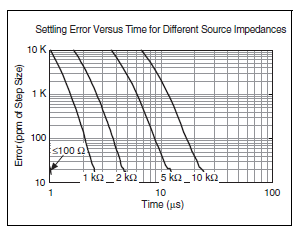
What you see, it's probably due to ghosting, and it should happen in the test panels as well if you measure two channels at once. This happens if you don't leave enough time for the channels to settle after multiplexing. Here is a table of specifications of 6363 which indicates the time of settling for various source impedances:
In your first picture as an attachment, the error is about 500 mV on a stage of 5V. It would be 10 per cent, or 100 000 ppm.
The same image, I see that you set a frequency 200 kHz 2 channels sample clock. Thus, the sum of 400 kHz to 2.5 would allow us to decide between channels.
Looking at the chart above, (2.5 US, 100 ppm k) is off the chart, but if extrapolate you the curves we could wait for your source impedance is somewhere around 5-10 kohm. Is this correct? If you have a link to the datasheet for your encoder, I'd be happy to take a look.
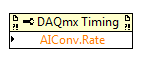
You do not see the error at 40 kHz 2 channels because it allows up to 12.5 US (1/80 kHz) for the settlement - in fact, DAQmx as default 11 us maximum convert the 6363 period when you buy slow enough to allow the time of settling in this case would be so 11 US. If you had to, you can reduce the clock rate to convert manually via a property node DAQmx Timing if 11 that we by default does not allow enough time for your application. The maximum conversion period which by default is DAQmx is the inverse of the maximum speed of the overall sample (in your case, 1 / 1 MHz = 1 US) + 10 to the United States.
Article ghost link above has some suggestions to eliminate ghosting, the most likely solution for you would be to implement a voltage follower if you need to acquire higher rates than allows the regulation of the multiplexer in view of your signal source. The voltage follower allows to considerably reduce the impedance as seen at the entrance of the DAQ card.
Best regards
-
NI USB - 6212 BNC analog input impedance matching
I just ordered a case NOR USB - 6212 BNC DAQ (should be delivered soon). I want to use to measure HV signals using a probe of high voltage of 1/1000 I have.
Now, datasheet of the probe (not a lot of info) says it has an impedance imput 100MOhm. I suppose that it consists of a simple resisitve divider, and if the ratio is 1/1000, I wait so to have a 99.9MOhm resistance in series with a 0.1MOhm resistance. However, the data sheet also specify that the probe is designed to be connected to an oscilloscope with an impedance of 1MOhm. As this input impedance is very low compared to the low value of the separator of resistance resistance, so I guess that the real resistance at the level of the sensor values 99.9MOhm and 0.11MOhm (to obtain the 0.99 and 0.1MOhm when it is connected to the oscilloscope for 1mW).
Therefore, given that the impedance of the USB-6212 according to the datasheet, the analog input is > 10GOhm, I expect to measure higher to true alternative voltages when connected to the acquisition of data from 10%. This assumption has a meaning?
What would be the best way to get around this? Do a calibration and correct the values acquired in LabVIEW code? Or should I add precision 1MOhm resistance at the same time to the acquisition of input data to decrease its resistance to entry to the value expected by the probe?
Thanks for your help!
Since you have a range of 1000: 1 I guess you also need bandwidth (I have a TEK 6015 A
 ), so you need based on the impedance input, a complex value, means he must not only watch but also the ability to input resistance (1 M). demarcation of the field probes have usually some elements of toppings to match the probe and the input scope. RTFM of the help of the probe
BUT a more serious point is that with your probe, you have a very high resistance. And if you look in the specification of the 6212 you will find on page 2 by mistake ppm in logarithmic scale graph! and even 100 k source impedance it not shown.
So I'm afraid that a simple 1 M on the DAQ entry can work if you're only measuring DC, and only if you use a channel on the acquisition of data. A workaround is an amplifier separate buffer with an impedance of good entry corresponding to the specification of your probe and a low output impedance.
-
Digital and analog inputs simultaneously - NI USB-6009 and NI USB-6212 - ANSI C
Hello
I'm reading at all times and at the same time analog and digital inputs. Digital and analog samples must be sampled at the same clock and acquisition should be started (triggered?) at the same time (I don't want, after some time, analog reception more digital samples - the opposite is also true).
I found an example (in C source code) "National Instruments\NI-DAQ\Examples\DAQmx ANSI C\Synchronization\Multi-Function\ContAI-Read dig Chan" and tried to run with two USB cards: NI USB-6009 and NI USB-6212. Unfortunately, the two results by mistake, as described below:
DAQmx error: the requested value is not supported for this property value.
Property: DAQmx_SampTimingType
You asked: DAQmx_Val_SampClk
You can select: DAQmx_Val_OnDemandTask name: _unnamedTask<1>
State code:-200077
End of the program, press the Enter key to exit-Is it possible sync analog and digital acquisition in the paintings?
-If so, how?
Thank you
Hello tcbusatta,
Two of these modules, USB = 6008 and USB-6212, support only timed software inputs and digital outputs. This means that you cannot define material timing (like finished sampling or continuous) for these modules. Digital lines can be retrieved or written once to each call DAQmx read.
This means that you will not be able to get any type of synchronization tight between the analogue and digital channels. You will need a Board such as the NI USB-6341 in order to synchronize the AI and DI closely.
-
Problem with a precision of analog input on PCI-6111
Hello
I'm reading an analogue signal which varies from 0-11 V using a card of acquisition data PCI-6111. The signal comes from a Tube set (PMT) which is part of a microscope configuration, so it is very important that the resolution of the analog input signal be as wide as possible generate quality images. According to the data sheet for the PCI-6111, the analog input resolution is 12 bits, which should correspond to a sensitivity of ~2.686 mV for my voltage range.
To test this, I set up a task to analog input with a 0-11 V voltage range to read samples of an analog output, which I wrote a simple waveform. Since the 16-bit analog output resolution that I assumed that it would not limit the accuracy of this measurement. I have attached the VI I used for this measurement below. The analog input data are saved not truncated in a text file.
Analyzing these data, I found that the real input sensitivity is ~9.766 mV, corresponding to levels of voltage exactly 1126,4 and ~ 10 bits.
Is there a reason why the resolution of analog input is much lower that it is indicated on the card? What are some of the ways I could improve the sensitivity of this measure?
Best,
Keith
Sorry, when you mentioned the specs, I thought you already had them. If this did not come with your Board of Directors?
-
LabVIEW think my NI USB-6008 has only analog inputs
I am using an NI USB-6008 box to run a route of analog input and analog output.
If I do a constant material DAQmx channel and out the finger tool and pull down... and it offers me 8 analog inputs on Dev1 and nothing else. I've nothing else connected to this computer, but the box USB-6008. A USB-6008 doesn't even have 8 analog input channels.
I'm a bit confused.
-
Continually acquire analog input, internal clock, break, Multiple device
I have a PXI chassis with 6 cards SMU-6363. I want to acquire data on the channels of each SMU-6363 map continuous AI, using the internal clock for timing. I need to use a trigger to pause reading of a DI on one of the cards SMU-6363 for a break and to reactivate the acquisition. I came across this example: https://decibel.ni.com/content/docs/DOC-12256/ , but keep getting error-201019 DAQmx start task "trigger break is not supported in a task to more devices. To configure the start of break in a multi-device configuration, you must use no more than one device per task and route manually clock in demand signals. »
The problem is that the configuration of I is made during execution by the operator. Sometimes they want to acquire data on one HERE through all 6 cards SMU-6363, sometimes they want to acquire data on each channel of AI through all 6 cards SMU-6363. What makes the task definition until manually route clock signals between devices for each rather difficult task.
Is there a simpler way to solve this problem?
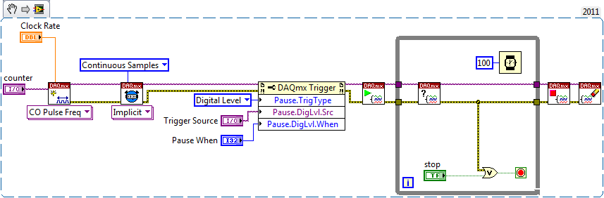
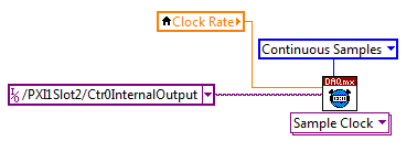
Set a task to output counter - something like this:
Next, configure your task of analog input to use the sample clock output of the meter:
Best regards
-
Integrate the outputs analog with analog inputs
I have a program that displays 2 analog output waves and a separate program that captures the analog data through several materials of NEITHER. I need to integrate the program outputs analog in my analog input program.
The program of analog output is fixed as "AO_Triggers_LowLevel.vi" and the analog input is fixed as "ExperimentDAQ.vi". When I try and integrate these programs I get 'error-200560 occurred at DAQmx waiting until the Done.vi' to my function to wait until it makes my task of analog input (background of the program). I think it is my mistake in the order that I'm wiring to the top of my son of error but I'm not sure. I watched several tutorials (Timing and synchronization features of DAQmx) but I'm totally stuck.
Any suggestions are greatly appreciated. Thank you!
Alberto M.
I think I've fixed this problem. I extended my flat sequence structure to include the lines of task and error of my task outputs analog and things seem to work. I'm still not sure about what caused my error and why it has solved the problem...
-
Read the counter timeout in synchronized to count-analog input
Ciao, Giovanni.
The two tasks are run in parallel so there is no guarantee which task starts first. I suspect that when you are away from the counter samples, it is because the task of analog input before starting the task of counter. In this case, the task of counter would be ready to accept examples of clock and may be missing some edges of the clock at the time wherever he is started.
One way to solve the problem would be to use the wires of the error in order to ensure the time started the task of counter in front of the task of analog input. You can also use a sequence structure to do that.
The counter is sampled on each edge of the sample clock HAVE no matter what you set the 'rate' of entry to the. When you use an "external" clock (external to the task that is), the driver uses just the entry rate to set some default parameters (size of buffer for example).
If you have any questions, feel free to ask!
Best regards
-
9174 triggered output pulses and analog input synchronization
Hello
I have a cDAQ 9174 with a 9215 analog and a 9401 module. I wonder if this configuration is suitable for my use: a trigger digital extern is sent to the system to trigger a task of analog input, trigger a generation of pulses, with another counter, count of trigger events. Using two counters on 9401, it seems I have no left Terminal at the entrance of my trigger signal. The trigger DAQmx vi does not show counters entries in the list of signals; and if I select a PFI line, an error that says that the line is already in use..., I missed a few obvious solution? I have change my 9401 to a 9402 did?
Thanks for any help,
Vincent
Hi Vincent,.
So, looks like you need a single line to use as input to trigger events and another line to use for a generation of pulse output. This should indeed be possible, since the 9401 has 8 lines that are configurable nibble (i.e. lines 0:3 could be configured as inputs, while the 4:7 lines could be taken out, or vice versa).
However, a big caveat with the 9401 is that the lines must be reserved before each task is started. This is a limitation of the direction of the line is implemented in hardware and is common as customers when something they using the 9401. Explicitly reserving your tasks before starting must correct the behavior if that is indeed what you see.
Best regards
-
Generation and acquisition of analog signals simultaneously on USB-6212
Hello, I am novice programmer DAQ trying to create (what I think is) something very simple.
I use a box NI USB-6212 and LabVIEW 8.5 is trying to generate a pulse train analog while recording a simultaneous analog input.
My first question is, is it possible?
Since I'm new to this, I use the DAQ assistant in LabVIEW. I can acquire a signal, I can also generate the desired signal, but I can't seem to operate simultaneously.
I have been successful in obtaining my program to work with both USB-6212, but I have to be able to do this with a single.
I have attached the block diagram and vi, I hope that's easy to answer the question, even if my research so far has left me empty handed.
Any help would be greatly appreciated!
Jon L
Hi Jon,
Well, first of all welcome to the DAQ programming! I took a peek at your code and published it with a device simulation very well, so I ran with the PCI 6251 card in my computer and he did not also get errors. Could you post the error code you get?
If I could figure out what is your error, I would say you encounter errors of buffer because it is too much overhead in the DAQ to wizards in the face of data rates. My suggestion would be to use the example called "Multi-Function Synch AI - AO.vi. This program can be found in the Finder for example of NOR (see Help"find examples in LabVIEW). "" It appears in the input and output material"DAQmx ' synchronization ' Multi-Function.
Can you give that a try and let me know how it goes? Thank you!
-
Problems with timing of analog input PCI-6111
I'm reading the analog input of a PCI-6111, who receives a square signal of 1 KHz with a cycle of 50%. I put the sampling frequency to 1 MHz and wait until the data points are 1 usec outside. When I check the signals received, it appears that the duration of each period of the square wave is 1.22ms instead of the expected 1.0 ms.
The following is a snippet of what I tried:
int NUM_SAMP = 10000;
DAQmxCreateTask("",&mTaskHandle);DAQmxCreateAIVoltageChan (mTaskHandle,
"(/Dev1/AI0","",DAQmx_Val_Cfg_Default,-10.,10.,DAQmx_Val_Volts,null); "
DAQmxCfgSampClkTiming(mTaskHandle,"",1000000,DAQmx_Val_Rising,DAQmx_Val_ContSamps,NUM_SAMP);
DAQmxReadAnalogF64(mTaskHandle,NUM_SAMP,10.0,DAQmx_Val_GroupByScanNumber,mDataBuf,NUM_SAMP,&numRead,);
Can you tell me what I am doing wrong?
Hello SNL_NB_1167,
A good place to watch code you know works would be the finder of the example. "" "" Open the finder example and navigate to hardware input & output "DAQmx" analog measures ' tension ' ContAcq - IntClk.prj
Run this code and see if you get the same results. If so, then we would know that it's a hardware problem and not a problem with the programming. If you see the correct behavior, then you have code that you can shape your out of. I hope this helps.
-
Calendar for the acquisition of data on the USB-6212
I am putting together a sound teaching laboratory. The basic idea is to send a pulse signal that powers a speaker, and then the acoustic signal travels down a waveguide where it is measured with a microphone and sent to a data acquisition. One of the important things here is that it is possible to measure the time of propagation of sound waves, so I need for data collection to occur at a time determined with reference to the sound output pulse. I tried with a sound card, but there are number of milliseconds of random jitter between the writing and the reading of the sound card.
So, I was watching the USB-6212. On paper it seems ideal: 2 outputs and lots of inputs. What I understand, it is possible to trigger analog outputs and data entered so that there is no jitter synchronization between them. The only question is this: I was thinking about using 2 analog inputs: a reference which collects through a microphone/speaker system to serve a normalization to the second chain that collects through waveguide (see diagram). The thing is that I need the "timing" on the 2 analog to be consistent and a jitter free so that it is possible to compare the phase of the signals that I collect. This will be possible using this data acquisition system, given that the ADC is multiplexed between the channels? There will be a delay between channels 2 and if so it will be known and deterministic?
Thanks for your help...
Ben
Hi Ben,
Cool application! To answer your question-Yes, there is a delay, and it is deterministic. Something to note about the 6212 is that your rate of multiplexing will be determined by the clock to convert. The clock to convert will operate at the faster pace of the device more 10us *. In the case of the 6212, with Max sampling rate of 400kS/s (aggregation), your pulse will produce each ((1/400,000) 12.5us + 10).
* 12.5us converts to 80 kHz, so at that point there, convert clock it simply runs at 1 /(aggregate rate). So to sum this up:
From 0 to 80 kHz: there is a lag multiplexing 12.5us
From 80 to 400: there is a shift of /(aggregate rate) 1
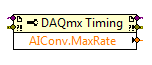
In addition, you can also set this rate through the DAQmx driver. "You can just use a property DAQmx Timing node' more' converted ' rate (or rate Maximum to determine the max).
If it's a problem, I advise to use a device with simultaneous sampling - let me know if you have any other questions. Take care!
-
NEITHER USB-6212 is not detected on the USB bus.
Hello
We use an NI USB-6212. We had installed it and works correctly on a test system.
Now it does not work and what are the symptoms:
-When it is connected to the USB the led next to the connector bus is not turned on.
-MAX software does not detect the jury.
Please, advice me on the steps to check if the Board of directors or eventually send it to repair.
Thanks in advance,
Diego.
Hi Gary,.
Following the expression "USB-Loader of Firmware" as a hint, I found the following link, related to my problem:
http://digital.NI.com/public.nsf/allkb/2E02F8EC5D0197928625758C005FFD8D
I got my computer the "USB-Loader of Firmware" service stopped, while it was "impossible to load the firmware information. Once started, it worked fine.
Thank you
Diego.
Maybe you are looking for
-
Help with connecting iPad 2540 deskjet all-in-one
Hi, I just bought the above printer, but it seems that I can't download drivers for my iPad (iOS 7.0.4) because no OS of iPad listed in the menu to download the drivers? I find that a little odd because it's a printer of the Tablet, or do I have to d
-
My msn does not open when I click on the butterfly, it indicates a problem to close
What does all this mean? -TimeCreated [SystemTime] 2012-05 - 17 T 21: 00:39.000Z EventRecordID 48694 Application of channel Cathy computer PC Security 17/05/2012-17:00:39 application Error 1000 (100) -EventData MSN.exe10.20.91.11004e1bccfbtxsrvc
-
HP Installer has stopped working
I try to install the printer software HP on a Windows 7 Professional 64 bit computer. When I run the file it complete extraction and then I get the error message ar 'of HP Installer has stopped working ". I have two options - 1, close the program,
-
Adobe reader - defective module error: Comctl32.dll
Running Windows 7 Home Premium, SP 1.Computer is ACER Aspire - laptop 4830TG with 8 GB of RAM, processor intel i5 - 2430M. Not sure when this happened, but I am unable to open Adobe Reader 10. The error indicates the fault module to be Comctl32.dll,
-
extension does not display JSLinter for flash
I installed JsLinter for flash on the crib of the extension. He said it would be the flash cc extension. How to do this on the extension. I need to understand what are the mistakes that I have in javascript. Is there another program that helps find