Digital calendar DAQmx
In the application, I need to acquire a sample of 16 channels every 5 seconds.
Currently, the application works when using
1 Daqmx Start
2 Daqmx reading (analog 1DBL N channel)
3 Daqmx Clear and then stop
There is a timer loop that waits 5 seconds before acquiring the next set of samples of conigured table. I am trying to replace this loop of timer using Daqmx schedule vi
My question is if DAQmx schedule vi is used are the correct setting on the next page to attach to acquire a sample every 5 seconds of 16 channels?
Yes, on MAX, this is the equivalent to 1 sample on request and in continuous operation. And Yes, by using the buffer material (DAQmx Schedule VI) would not give any advantage of this. That would be better spent if you do a very fast acquisition. However, for the acquisition of once every 5 seconds, the determinism of your operating system should not be significantly detrimental to your calendar.
Kind regards
Tags: NI Software
Similar Questions
-
I keep me going in circles. I need to understand this because it seems so simple.
I have a digital waveform with a frequency of arbitrary clock. I want to send this waveform on a device USB-6259. I was able to do this with an analog signal and digital signal gives me problems.
For example, if I want to send a 7500Hz digital signal, I need to have the material, since the time of the application appears not to get up to about 1 kHz. But when I try to set up the schedule, it never seems to work. I'm going to make mistakes like that...
"External sample clock source must be specified for this application."
How can I configure things so this thing can clock the stuff at a particular rate. The analog part of the device doesn't seem to have a problem doing this, I do not understand why the digital side needs an external clock.
A modified version of one of the examples is attached.
VI attached
-
Outputs digital synchronized DAQmx
Hey, I am trying to send two synchronized digital signals of a PCIe-6420 device.
Here is my code:
DAQmx configure clock
DAQmxErrChk (DAQmxCreateTask ("Clk", & taskHandleFRQ));
DAQmxErrChk (DAQmxCreateCOPulseChanFreq(taskHandleFRQ,"Dev1/freqout","",DAQmx_Val_Hz,DAQmx_Val_Low,0,ManchSampClkFreq,0.5));DAQmx digital output configuration
DAQmxErrChk (DAQmxCreateTask ("Harmony", & taskHandleHarmony));
DAQmxErrChk (DAQmxCreateDOChan(taskHandleHarmony,channel2,"",DAQmx_Val_ChanPerLine));
DAQmxErrChk (DAQmxCfgSampClkTiming(taskHandleHarmony,"/Dev1/PFI14",ManchSampClkFreq,DAQmx_Val_Rising,DAQmx_Val_ContSamps,sendCount));DAQmxErrChk (DAQmxCreateTask ("DOchan", & taskHandle));
DAQmxErrChk (DAQmxCreateDOChan(taskHandle,channel,"",DAQmx_Val_ChanPerLine));
DAQmxErrChk (DAQmxCfgSampClkTiming(taskHandle,"/Dev1/PFI14",ManchSampClkFreq,DAQmx_Val_Rising,DAQmx_Val_ContSamps,sendCount));DAQmx Configure similar output
DAQmxErrChk (DAQmxCreateTask ("AOchan", & taskHandle));
DAQmxErrChk (DAQmxCreateAOVoltageChan(taskHandle,channel,"",0.0,10.0,DAQmx_Val_Volts,));
DAQmxErrChk (DAQmxCfgSampClkTiming(taskHandle,"/Dev1/PFI14",ManchSampClkFreq,DAQmx_Val_Rising,DAQmx_Val_ContSamps,sendCount));DAQmx write code
DAQmxErrChk (DAQmxWriteDigitalLines(taskHandleHarmony,sendCount,0,10,DAQmx_Val_GroupByChannel,SendManchHarmony,,));
DAQmxErrChk (DAQmxWriteDigitalLines(taskHandle,sendCount,0,10,DAQmx_Val_GroupByChannel,SendManchData,,));
DAQmxErrChk (DAQmxWriteAnalogF64(taskHandle,sendCount,0,10.0,DAQmx_Val_GroupByChannel,SendManchAnalog,,));Starting code DAQmx
DAQmxErrChk (DAQmxStartTask (taskHandleHarmony));
DAQmxErrChk (DAQmxStartTask (taskHandleFRQ));
DAQmxErrChk (DAQmxStartTask (taskHandle));Only problem, is that I get "error DAQmx: NI service platform: the specified resource is reserved." messages.
The name of the task associated with the error is DOchan: aka: taskHandle. If I rearrange the code such as taskHandler events occure before the equivelents to taskHandlerHarmony, then errors are associated with harmony: aka taskHandleHarmony instead.
That I am I doing wrong and how should outputs digital syncornized be implimented instead?
Think of the fifo in a block of memory that is the same width as the digital port where each bit corresponds to a single digital line. The samples are transferred from this FIFO to the port in written all over port (there is some logical activation, so only those lines that are configured in your output task are actually updated each sample clock). DAQmx will combine the data you write for if make sure that the correct data at the scale of the port gets written in the FIFO. DAQmx for this by looking at the configuration of the group 'line' in DAQmx create DO canal and the "dataLayout" specified for the function DAQmxWriteDigitalLines.
You have two lines you have set on DAQmx_Val_ChanPerLine. This means that when you call DAQmxWriteDigitalLines, it will be expected to see enough data to two data channels. The way in which these data are specified is configured by the dataLayout. By specifying DAQmx_Val_GroupByChannel, you say DAQmx data for each channel to be grouped. You should do these groupings in the same order that you specify your channels.
So consider the following:
DAQmxErrChk (DAQmxCreateTask ("DOTask", & taskHandleDOTask));
DAQmxErrChk (DAQmxCreateDOChan (taskHandleDOTask, "Dev1/port0/$line0", "", DAQmx_Val_ChanPerLine));
DAQmxErrChk (DAQmxCreateDOChan (taskHandleDOTask, "line1/port0/Dev1", "", DAQmx_Val_ChanPerLine));
DAQmxErrChk (DAQmxCfgSampClkTiming(taskHandleDOTask,"/Dev1/PFI14",ManchSampClkFreq,DAQmx_Val_Rising,DAQmx_Val_ContSamps,sendCount));We will alternate digital high/low between our two lines (we will write the 10 values of each line), with the exception of this last point, where we will write two lines high
The data should be written in the corresponding line bit position (if I remember correctly)which means you want to manipulate the lsb for the 0 line, and line 1 manipulate you the 2nd lsb.
Int32 [10] line0Data = {1,0,1,0,1,0,1,0,1,1}
Int32 [10] line1Data = {0,2,0,2,0,2,0,2,0,2}
Int32 dataArrayByChannel [20];
Int32 dataArrayInterleaved [20];
for (int32 i = 0; i)< 10;="">
{
Group data through
dataArrayByChannel [i] = line0Data [i];
dataArrayByChanne [i + 10] = line1Data [i];
Group the data by scanning
dataArrayInterleaved [i * 2] = line0Data [i];
dataArrayInterleaved [i * 2 + 1] = line1Data [i];
}
We can write data in one of the formats that we just built, but we must provide DAQmx with the correct dataLayout.
DAQmxErrChk (DAQmxWriteDigitalU32 (taskHandleDOTask, sendCount, 0, 10, DAQmx_Val_GroupByScanNumber, dataArrayInterleaved, NULL, NULL));
Alternatively, we could write per channel. If we chose, it would look like this (you wouldn't do both).
DAQmxErrChk (DAQmxWriteDigitalU32 (taskHandleDOTask, sendCount, 0, 10, DAQmx_Val_GroupByChannel, dataArrayByChannel, NULL, NULL));
DAQmxErrChk (DAQmxStartTask (taskHandleDOTask));
In both cases, DAQmx must write the following data to the FIFO:
x 1
x 2
x 1
x 2
x 1
x 2
x 1
x 2
x 1
x 3
In this way, the data written to each line are combined by DAQmx then written to the FIFO. Allows you to specify the data for each channel individually.
It was quite long, but I hope it will answer your question. If I was not clear, please let me know.
Dan
-
Hello
I collect the load data and discharge of a capacitor during different periods.
Using the attached circuit, what the best way to define the sampling per channel and I can apply hours measuring without getting the slow operation systems.
Thank you
I don't see an attached circuit. It's a block diagram.
1. continuous samples, do NOT connect to the top the 'number of samples per Channel"on the VI of Timing DAQmx. You simply limit your buffer, which want to keep very large.
2. There is no need waiting for them in the loop. The DAQ reading will limit your loop rates.
3. There is no interest to read this file in spreadsheet each time you an iteration of the loop. Move this reading before the loop. This will speed up your loop a little.
4. set the sampling all that you need for your measurements. The number of samples to read the DAQmx Read should be based on, however many samples you want to process at a time. Just make sure that your code can follow your sampling of data acquisition rate by increasing the number of samples to be read by iteration or lower your sampling rate.
-
Analog acquisition and digital simultaneous DAQmx
Hi all
I use the USB-6212 acquisition card to acquire analog and digital inputs. However, I encountered some problems that I don't know how to solve.
All channels (analog and digital input) is independent of one another, but should be acquired at the same time (using the same clock, I think), but I'm not managing to achieve; In addition, I can not put a task so that the digital acquisition is made by "continuous sample" - the error says it is not supported, but I saw this configuration in other examples in this forum.
The only way to get a digital waveform must keep pooling the entry? And, therefore, also in common analog input? Is it not this costly approach from the point of view resources?
Best regards
The decrease of performance will be determined by the speed of your computer and your USB hub.
I think that to get the hardware timing of digital I/o on a USB device, you're going to have to step up to a card in the X series as the 6341, but I'm not sure about this. You can find this specification under the specifications of each product tab. Looking for 'Material' under DIO > Timing.
-
Why Digital Edge in Trigger.vi start to make some sort of timeout?
Hi I do a manual release on my hardwareboard by inserting a 5 volt source the triggerchannel selected a few seconds after I push the Start button.
The generation ever begins. But if I put the trigger very equal to the sample clock external works listed in annex vi.
For example, I use PFI7 as source of outbreak which is also the source of the sample clock.
Could someone explain to me?
Sincere greetings,
Lasse
We can't simply insert a wire with a 5 V potential to PFI6 for example if PFI6 is used as a trigger for "Start Digital Edge" daqmx - vi. The PIN is floating and inserting just 5V does not guarantee a low aboard high.
If I use a potentiometer to pull on the low channel first, and then increse the tension, the trigging happens.
-
Output broken for writing DAQmx
Hello
I need emergency assistance with a problem I have with write DAQmx. The 'DAQmx write VI' is located inside a while loop that repeats every 20ms. I use queues to transfer data between several asynchronous VI and the data does not update all 20ms. Because I'm not going to tie the whole project I faked the timing of 20ms to 'Wait for next ms Multiple' vocation. What happens is I will send 20ms of data to the VI DAQmx writing, he will have all the data output with 4ms can sit idle for 16ms. I implemented the task for the DAQmx example 1000 per channel at a rate of 50 kHz, which should take all 20ms to the exit. I also checked the waveforms of entry the entry have 1 k samples and a detachment of the 2nd-5. When I went from the DBL 2D table has not changed. I want to emphasize that all data is sent into the 4 DC. It's confermed visulaly and with the node 'written examples.
I did a test where I hosted my VI to run as fast as possible. In this case, the output was a sine curve, but looking more closely, I found that the output frequency of 25 Hz 5 times faster than the signal that I sent to the writing DAQmx VI. In addition if you limit the loop to 10ms iterate the data is output for 4ms and the idle 6ms.
I know that everything is configured correctly. I rechecked the data I sent you the properties of the task. She should be out correctly, but it isn't. I tried calling support NEITHER and he was not particularly helpful.
The equipment I use is a PXI 6723 AO map. I will attach a vi that anyone could run and I will attach a picture of the exit on an oscilloscope. Thnak you for the help
-James
I solved my problem. I needed to add a calendar DAQmx and DAQmx writing change the task before entering the while loop. I use the calendar to set the mode of the sample and the source of the command, while simple DAQmx writing sends and matrix of zeros. With these added it works very well.
-James
-
USB 6525 6501 digital for output to the step motor
Hello
I try to use USB 6501 or USB-6525 out of step motor signals which command the stepper motor. My questions are
(1) do I 6525 USB, I'm not sure the function of it (perhaps as a relay).
(2) now I connected input 5V for USB-6501 "+ 5V" pin and GND to pin "GND". On the other side (output side), I connected ' enable '(from motor drive) to P0.0. 'direction' to P0.1 and GND to GND. Can I use the express signal to test, the error says "lack of entry."
(3) I guess the next step is programming labview. Does anyone know of similar examples?
Any help would be appreciated!
Melody,
If the engine must input external logic level I advise to use the USB-6501, which is just a digital I/o card. The USB-6525 housing does not have the digital outputs to control your motor drive. If I understand correctly you just try to turn the motor on and off with a digital signal. It seems that you also provide your drive motor + 5 v and GND. The USB-6501 has channels for + 5V and GND. I've attached an example of navigation that controls the outputs digital using DAQmx and LabVIEW. This specific programme allows to control 8 digital output lines, but it looks like you don't have one. If the engine waiting for you just a strong to put logic in operation and a logic low to shut down this program example will be able to turn on or turn off your engine. Just connect one of the USB-6501 digital output lines and then use the program to this line of control.
I don't really know any reason, you need to use the USB-6525 it seems to me that the USB-6501 run action you need. I hope this helps.
-
How to build square 3 ph pulses and use them to trigger the two analog inputs.
Task:
1) generate continuous 1 Hz ms 45 pulses on three lines of output offset 120 degrees.
Other neighborhoods, three phases (three outputs) 120 degrees out, but instead of sine wave should be a volt 5ms 45 along with a second ground pulse. I need these impulses to control an external circuit. The tolerance of 1 Hz is loose, but 45 ms must be at 100 us.
(2) measure (trigger) two independent DC voltage over 45 ms 50 ms after each front (leader) amount of each pulse. 45 to 50 ms must be 100 us.
Other neighborhoods, begins each measure 45 ms for the DC source #1 and 50 ms for the source DC #2 after opening (rising edge) of each pulse for total of six measurements per second 1 (by 1 Hz cycle).
(3) an analog output must provide ongoing (to be booked) negative DC voltage to be used as a source of supply for external circuits.
I timely when I can generate the 45 Hz by using CO (0) 1 ms pulses continuously and the trigger I (0) on falling edge. I (0) is hard wired to triggering I (0).
How I do HAVE another (1) and two other lines (two phases) and link them to HAVE (0) and HAVE (1)?
Equipment: LabView 8.6.2, PCI-6221 (37-pin)
Hi behappy.
Thanks for posting and welcome to the forums EITHER! I think we can get what you need with the variety of the 6221 37 pins:
(1) our machines of the M series have 2 counters, so you cannot generate all the impulses of 3 of these alone. A solution would be to use outputs digital correlated.
Unfortunately, the 37 pins 6221 has only two IO digital correlated, so you should use a strange mixture of digital meters and IO to implement three impulses. It would still be feasible - for example, you might use a counter for a time base for the digital i/o lines and the other counter to the third output pulse. You would have to match the beginning of the two counters to ensure the phase of your signals.
2) there are essentially two parts to this question, so I'll try to split:
(i) combine the three impulses together to generate a single sample signal out of. I think this would be doable on a different set of M with a higher number of digital I/o lines correlated using change detection (see the user manual of M series). However, at this stage, we are just out of digital lines correlated to use, and I don't think that's possible on the 37 pins 6221.
If you use the 6221 37-pin, which you will probably need to do is to provide your own external circuits OR three pulses together.
(II) get the 5 ms delay to enjoy your second channel. Since you have already discovered that you can sample the falling edge of the digital signal for the delay of 45 ms, you would just add another delay of 5 ms before taste you your second I. You should be able to do this by setting the clock to convert DAQmx frequency (5ms corresponds to 200 Hz). The clock to convert, it's what actually sampling data (keep in mind that the boards of the M series are multiplexed).
To do this, simply use the property calendar DAQmx node, then select: more > converted > rate.
(3) this one is easy - we have not yet used all channels of AO.
So the 37 pins 6221 is a little less ideal because you have not enough correlated digital i/o to make the generation of pulses or change detection - but he has yet to do the job if you can combine the three impulses yourself outdoors and don't mind not using the additional counter to generate the third impulse.
I hope this helps, if you need any help to find relevant examples, please do not hesitate to post in return. Thank you!
-John
-
samples per channel and the number of samples per channel
in my DAQ mode samples finished program, there are two screws: timing and read.vi DAQmx DAQmx.
I have to set the parameter to "samples per channel" DAQmx timing.vi and 'number of samples per channel' on DAQmx read.vi... Is there a relationship between these two?
My laser runs at 1 K Hz. I want to go to the wavelength, wait for a number of shooting lasers, read the data and move on to the next page...
Thank you
Lei
In your case, the VI will acquire the lesser of either:
The "samples per channel" that you have defined on the timing DAQmx VI
-OR-
The number of iterations of your for loop (N) times the 'number of samples per channel"that you have defined on the DAQmx read VI
The "samples per Channel" VI DAQmx of timing for a finite acquisition dictates how many samples the DAQ hardware should acquire in it's onboard buffer before indicating that the acquisition is complete. "The number of samples per Channel" on the read DAQmx VI dictates how many samples the DAQmx driver must return buffer on board the aircraft to your application.
Let's say the "samples per channel" on the calendar DAQmx VI is set to 50. Thus, the card will acquire 50 samples and place them in the edge of the buffer, then stops. Suppose we have the 'number of samples per Channel"on the DAQmx reading VI the value 3 and what we call the VI in a loop For which runs 10 times. Thus, every time the DAQmx lu VI is called, it will wait until there are at least 3 samples in the buffer, and then return these three. We call the VI a total of 10 times, then we will answer 30 total samples. Thus, the last 20 samples acquired the card remains in the buffer and are destroyed when the task is disabled.
Now let's say that we increase the "number of samples per Channel" on our DAQmx Read VI at 10. VI Read will wait until 10 or more samples are in the buffer, and then return these 10. Thus, we will be back all 50 samples map acquired by the 5th iteration of the loop For. The 6th time we call him VI DAQmx Read it expires, because there will never be another 10 samples in the buffer, and the VI returns a warning.
This clarifies things?
The purpose of this behavior is to allow you to both set the total number of samples that the DAQ hardware will acquire and also control how much of these samples is returned whenever you call the DAQmx Read VI.
Kind regards
-
Hello
I just started using an NI USB-6008 box. At this point, I don't need to fill all the specific tasks other than learning to use the device. I used a fair bit of LabVIEW but never with this kind of material, and I would like to help to understand it please.
In particular, I have attached a VI in which I try to get an analog signal through the USB-6008 and read again (also with the USB-6008 - I wired the pins together). However, I do not understand what is happening when I run this VI. I expect the output a sine signal of 10 Hz for 1 second, 0.1 seconds record and see 1 full cycle of the sine wave. In practice, I read about 10 cycles and constant tension then. Presummably, this means that either the reading continues for more than 0.1 second, otherwise the output signal is more than 10 Hz.
I also tried to use the related calendar DAQmx screws with the output pin to try to adjust the output rate (samples/s) but everything that I've tried return errors. I also tried to open some examples NOR, but these errors returned as well and I still just try things on mine.
Did I miss something obvious here, but any help would be appreciated!
Edit: I had to update this post & attached VI I had made mistakes. The default values on the front panel show what I see after the execution of the VI.
Orbital Hi,
As far as I know, you will need to use the DAQmx Read and VIs write in loops and functions of synchronization to determine data rates you want.
I also did a quick search and found a white paper which you may find useful: http://www.ni.com/white-paper/9541/en/
Kind regards
-
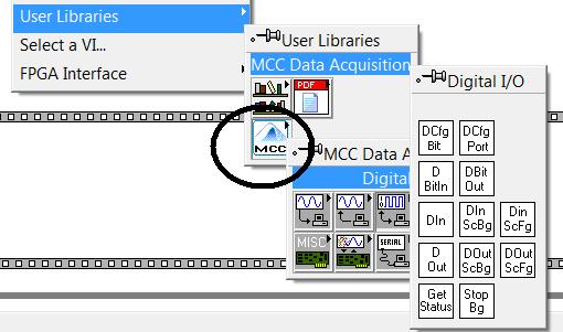
How to connect USB-ERB24 devices to labview application
Hi iam, iam new to labview application development using NIUSB-9421 as module input and USB-ERB24 in the output module. I have sucessfully added NIUSB-9421module to my application using 'Digital IO DAQmx create Virtual Channel.vi'. But cannot add this module USB-ERB24 iam. Can someone please tell me how to detect "USB-ERB24" this module for my labview application please tell me...
I don't think that you will be able to use DAQmx with MCC USB-ERB24. You must run InstaCal (driver of MCC) to install the USB-ERB24 and get a card number for this unit (and build your application with the MCC screws).
I have LV2009 and I'm not able to open your USB_ERB24_test.vi. The attachment is for USB-ERB24.
Jean-Marc
-
overflow memory for the producer consumer
I'm trying to save data from 4 ports to 40.96 Mhz. using a producer consumer architecture and a PCIe NI 6527 B using an external clock.
I inherited code which works for 2 ports. I tried to add additional ports and changed the size of the data to the DAQ.mx queue and data. Launch the program several times, reach conflicting error messages after less than 2 seconds from the beginning:
Error 200284: Some or all of the requested samples are not yet acquired. [...] To make available samples more quickly, increase your sampling rate
200361 error: Overflow memory device on board. Due to the limitations of system and/or the bandwidth of the bus, the driver could not read the device fast enough to follow the flow of the unit. Reduce your sampling rate.
What is a race condition between the error messages, a problem of timing of start or something else?
I approach, how to debug these types of problems? How can I determine what is causing the error? I can't single step through because I'm at the wheel of sampling with an external clock.
Running on labview 2012 Windows XP on the machine who's 3.17 GB of ram.
Try to reduce the size of your buffer. In fact, simply leave the calendar DAQmx unwired. The size of the buffer must be large enough by default. And then also try to read less data at a time, as data instead of data 500ms 10ms. What I suspect here, it's that the DAQmx buffer is too large and therefore must use the hard drive for part of the buffer, to slow things down a lot.
Other notes here:
1. do not use the time-out to stop your loop of consumer. Your producer should send an order of a certain type to your consumption by telling it to stop. In this case, I would use an empty array. And then, you must release the queue after the loop of the consumer.
2. you want a constant FALSE to Append Array/String input size of the binary file write. This will remove the 2 I32s at the beginning of each table that you write. Eelle are here to tell the size of the table being written. But since you are just data flow, I doubt that you care about those.
3. instead of the entire setup of producer/consumer, have you considered using just the DAQmx Configure Logging VI do DAQmx stream directly to a TDMS file for you? Makes things much faster and much easier on you.
-
Mounted daqmx calendar/trigger on 2 chassis mxi-express
I have 2 chassis SMU (including one with a RT controller) connected with SMU-SMU/8384-8381-MXI-express boards.
I can see all the devices in both chassis and can configure DAQmx tasks in each chassis individually, but I can't create any single task with a device of two chassis. When there is a feature of two chassis in the task, I get:
Error-89125 occurred at DAQmx start Task.vi:7220002
No registered trigger could be found between the devices in the range... Make sure that there is a trigger line available on the bus triggering shared between devices.
Is this possible in the software? Or should I add material? I can't find any docs or examples on this subject, other than a promising article on Veristand (ni.com/white-paper/14637/en/, #2) but I can't implement in MAX or NV. Timing is not critical (50 to 100 ms is very good), I just need many devices on 2 sites, so the MXI solution seems to fit in. I thought the solution was to use the local clock on each chassis and set up a trigger shared/exported, but impossible to find something that works.
Thank you!
Hey brimcd,
You are right; It is not a way to send a trigger between chassis without timing card. This link goes into a bit more detail: http://digital.ni.com/public.nsf/allkb/D91582EBF0810F4486256E70004E4145
-
DAQmx Read simultaneous calls on the same digital line
Hi all
I use v10.0 LV 32-bit on Windows 7.
I use DAQmx Read (in a task) to check the value of a digital line. Is it OK to do this in two different locations in a program at the same time for the same digital line? Or I have to put a wrapper around reading to force operations to be sequential?
Thank you
ZolaWhen you need to expose the capabilities of resources to multiple areas within a project (expand the scope of a resource) it is common to wrap the resource in an Action engine to encapsulate the resource functions. See here for an example of a 'Module on resources' material and a discussion animated about how this code help development construction and avoid resource conflicts. If you have not read famous nugget again – he of Ben is a link in my tag "Required_Reading".
Or more directly. Yes, you should encapsulate these readings DAQ to avoid suspended
Maybe you are looking for
-
I bought 50 GB of extra storage, but always to 5 GB
Hello I bought 50 GB of storage, but icloud is always to 5 GB and I was charged 2 times on my account. Would you help me please? Thanks in advance
-
My cat went through my keyboard and somehow or another stop function that allows me to open a bookmark from the bookmark drop or bookmarks I have shortcuts to. Also, when I right click on a site marked with a bookmark to open it in a new tab, that no
-
All dropdowns flash and disappear, the main firefox window gets drawn over them.
It is an error very embarrassing with the latest version of Firefox on Windows 7, which is also updated are all my drivers. The problem is that whenever a drop-down dialog box or a menu is open, the main Firefox window (containing the web page open)
-
officejt pro 8500 a909a: my printer supports eprint
all I want to know is in charge of my eprint printer and, if yes, where can I find specific instructions to enable it.
-
HP Pavilion dv7-1245dx hard drive replacement issue
Can I use any manufacturer 2.5 "disk for this laptop? Looking to upgrade to the bigger drive. Not sure about the sata and sata II speeds rpm or cache sizes, or if they are important. Thanks in advance. Currently: HITACHI HTS543232L9A300 320 GB