Mounted daqmx calendar/trigger on 2 chassis mxi-express
I have 2 chassis SMU (including one with a RT controller) connected with SMU-SMU/8384-8381-MXI-express boards.
I can see all the devices in both chassis and can configure DAQmx tasks in each chassis individually, but I can't create any single task with a device of two chassis. When there is a feature of two chassis in the task, I get:
Error-89125 occurred at DAQmx start Task.vi:7220002
No registered trigger could be found between the devices in the range... Make sure that there is a trigger line available on the bus triggering shared between devices.
Is this possible in the software? Or should I add material? I can't find any docs or examples on this subject, other than a promising article on Veristand (ni.com/white-paper/14637/en/, #2) but I can't implement in MAX or NV. Timing is not critical (50 to 100 ms is very good), I just need many devices on 2 sites, so the MXI solution seems to fit in. I thought the solution was to use the local clock on each chassis and set up a trigger shared/exported, but impossible to find something that works.
Thank you!
Hey brimcd,
You are right; It is not a way to send a trigger between chassis without timing card. This link goes into a bit more detail: http://digital.ni.com/public.nsf/allkb/D91582EBF0810F4486256E70004E4145
Tags: NI Hardware
Similar Questions
-
I have a system with a PXI 1085 and a NI SMU-PCIe8371, NI SMU-PCIe8372 PCI Express control of PXI Express, which was controlled by a Dell Precision T5600 with Windows 7 and a NVIDIA Quadro 2000 graphics card. I had installed the software compatibility MXI and things worked very well. I could see in MAX and use the cards in the chassis. I decided to upgrade the 8371 to the 8381 (SMU-PCIe8381 NI, NI SMU-8384 PCI Express (x 8 Gen 2) control of PXI Express).
I put 8381 in x 16 slots empty (there are no x 8 slots on the motherboard). When I turn on the computer, if I have the chassis connected monitor does not display anything and that even if the computer gets power, he does not seem to start, if I unplug the chassis, then the computer starts very well.
In a similar thread user deleted all cards except the MXI Express card and it worked, I tried to remove all of the cards in my chassis, with the exception of the SMU-8384 (of course) and I still have the same problem.
This gives a test:
Press the switch DIP Compat BIOS on the PCIe-8381 in position (position 1 of the switch, should be labelled). This indicates the card that you use software compatibility MXI. This should allow the system startup and one of two things will happen...
(1) things work very well, and you're all set.
(2) the system starts, but you won't see the chassis.
#2 case, install the latest version of the software compatibility MXI, reboot and try again. The thought here is that it is possible that if you have installed this software there are long enough (several months) that you are on a version of the software which does not support the 8381. The latest version should work fine.
-
I can connect an NI MXI-Express RIO 9154 off the cRIO-9068 serial?
I would use the cRIO-9068 a new system but will need a second wreath off the first chassis. Can I use NI MXI-Express RIO 9154? If so, how to connect the MXI cable until the 9068?
Not the MXI Express, but you can use EtherCAT: chassis NI 9144 8 locations EtherCAT Slave for C series i/o Modules
-
NEITHER 9219 fully supported on the RIO MXI-Express?
I'm trying to choose for my RIO MXI-Express chassis cRIO modules and I fell on the NI 9219 universal module. While reading the user guide, I noticed that it is said in two separate sections as the 'Digital mode' and "Mode of Contact open' is 'supported only in CompactRIO systems." As I don't have the actual hardware for me to test, I created a LabVIEW project using the FPGA Wizard and he had to instantiate a chassis of RIO MXI-Express (NI 9159) connected directly under 'my computer '. I then load a NI 9219 module and set 0 "Digital In" mode and Channel 1 channel mode "open Contact". After that I dragged & filed two channel nodes in my block diagram and I was happy to see that the LabVIEW compiler thinks that everything is OK.
So my question is, whenever I read "is supported only on the CompactRIO systems" does also include MXI-Express RIO systems as well? If so, it seems that some documentation for cRIO modules should be updated.
NEITHER 9219 plug: http://sine.ni.com/nips/cds/view/p/lang/en/nid/208789
NI 9219 user guide: http://www.ni.com/pdf/manuals/374473e.pdf
Thank you
Hi SeanDonner,
Yes, the RIO MXI-Express is deemed part of the cRIO system. In addition, for lovers of the future forum, the chassis Ethernet RIO and EtherCAT RIO are also part of the cRIO system.
-
MXI-Express in an expansion slot ExpressCard from NVIDIA does not.
I'm trying to get a DELL Latitude E6400 to connect to the controller of the PXI-8360. I use Windows 7 64-bit. I think that the problem may be that my DELL's ExpressCard slot is actually an expansion of NVIDIA ExpressCard slot and therefore not directly controlled by the BIOS (I guess). I use 8.6.1f1 of LabVIEW with as much current as I can find, especially MAX 4.6.2 and the PXI Platform Service 2.5.3 and Nov09 of device drivers. I have searched through the forums and tried solutions as much as I can find. The DELL BIOS upgrade A19, I tried the compatibility software BIOS MXI-Express 1.2 but I can't install it because the installer complains that my system is not 32-bit. I'm about to update the NVIDIA driver but I have my doubts about this work. My suspicion is that because housing ExpressCard is a slot on the NVIDIA card it will be difficult, if not impossible, to find a workaround.
Any thoughts?
If there is only 1 bridge looming, the card is probably in compatibility mode, which requires a driver.
Try plugging (ExpressCard only) on a system with the driver installed, and then run the configuration utility (all programs-> National Instruments-> MXI - Express-> Configuration card ExpressCard-8360) and disable compatibility mode. Then, it should work in your other system.
-Robert
-
I created a program that reads analog data and draw a waveform, but I need to stop the program when the voltage drops to a certain tension. When I tried the analog edge trigger it showed the error in the subject:
Reason: The requested value is not supported for this property value. The value of the property may be invalid because it is in conflict with another property.
Property: Trig startup type
Requested value: analog edge
You can select: Digital Edge, no
I understand what the analog trigger is not available for my DAQmx version, without again getting equiptment, can I use a trigger to stop reading data at a specific voltage?
How to start and stop a similar read digital triggering?
Thanks in advance!
Ah! Well, then the Boolean value of status would be connected to the State of the thread of the unbundled error, Boolean stop to the stop button and the Boolean value to the right would be the stop for loop itself... so something like this (see image). This is an excerpt from LabVIEW 2014, so it can not easily fall in your version, but I hope it's clear enough on how you can wire it to the top.
-
200077 took place at node DAQmx property trigger
I get the following error message when you try to set up an analog trigger on my USB-6343. The attachment shows the part of the VI that produces the error. I'm trying to trigger the same channel that I am seized of data if it is a problem.
There was a similar position involving a USB-6229, who concluded the device did not support the analog trigger but I looked at the specs for the 6343 and the title of the analog input function, it lists Start Trigger.
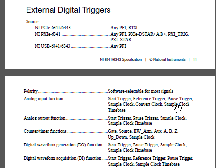
The 6343 supports analog not triggering (page 2 of the specifications).
The section you are referring is under the triggers section external digital (although it is confusing because of the section being split into 2 pages):
What document probably means, is that a digital external trigger can be a relaxation of beginning for a task of analog input. If you need an analog trigger, you should watch the 635 x or x 636.
Best regards
-
Several synchronization AO-DO-DI via DAQmx, external trigger devices
Having trouble getting the digital input to trigger analog output unit.
I have 2 AO cards (although I'm testing only with 1 device AO)
2 cards DIO - using one for output, one for input
All 4 cards are connected via a RTSI cable, and the cable is correctly condfigured in MAX, all 4 devices added to the cable.
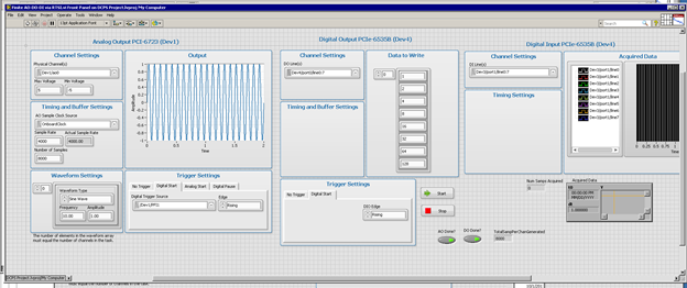
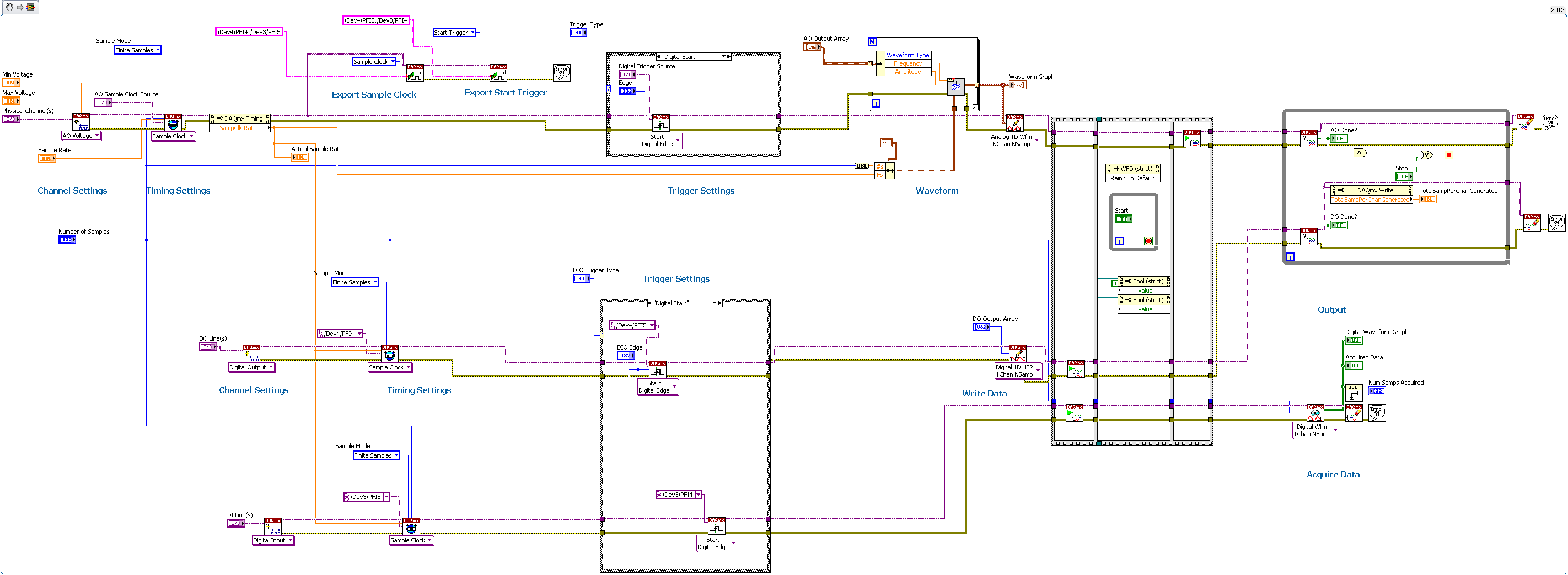
I consider the AO the 'master' unit map In this test, I plead for a finite number of samples, and I'm outside triggering map AO.
As you can see, iI uses Signal export, export the AO and AO Start Trigger sample clock to DIO cards.
I'm using Labview 2012 on PC Windows 7.
The digital output is waiting for the AO trigger and appears off the coast of the AO sample clock synchronizing.
The digital input expires if I only fire at the time, so he does not expect relaxation.
any ideas? I tried all kinds of combinations.
Never mind! I solved the problem with digital input without waiting for the external trigger.
I just had to set the time-out waiting-1, so that he would never expire, and so he will wait for the trigger.
-
I keep me going in circles. I need to understand this because it seems so simple.
I have a digital waveform with a frequency of arbitrary clock. I want to send this waveform on a device USB-6259. I was able to do this with an analog signal and digital signal gives me problems.
For example, if I want to send a 7500Hz digital signal, I need to have the material, since the time of the application appears not to get up to about 1 kHz. But when I try to set up the schedule, it never seems to work. I'm going to make mistakes like that...
"External sample clock source must be specified for this application."
How can I configure things so this thing can clock the stuff at a particular rate. The analog part of the device doesn't seem to have a problem doing this, I do not understand why the digital side needs an external clock.
A modified version of one of the examples is attached.
VI attached
-
PXI-8360 (MXI-Express) PCI-8361 + Dell OptiPlex 9020 = "device cannot start." (Code 10) »
Hello
I have a chassis PXI-1050, conencted to a Dell OptiPlex 9020 via a PXI-8360 and a PCI-8361 (identified as 199392B - 01L). It is Windows 7 64-bit. I can't start Windows very well, but MAX can't see all my PXI hardware. The Device Manager has also 2 inputs "PCI standard PCI to PCI bridge" with exclamation points.
I placed an old FireWire PCI card in the same dwelling and recognized PC. Thus, the slot went very well.
I transferred the PCI-8361 to an old PC that contains older drivers, and he acknowledged all my PXI hardware. For example, PXI gear works fine.
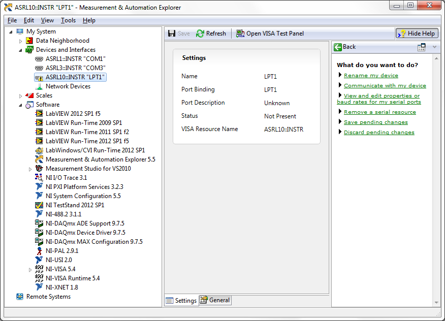
What could be the problem? Here's a screenshot of my software OR installed. I think I installed all the drivers I need. I checked NI Update Service; There is no update of Critcal, and only updates and Service Packs listed are 2013 LabVIEW and TestStand 2013.
JKSH,
I look in that little bit more and think that I now know enough to be dangerous.
The BIOS allows the PCI Express native control mode in Windows. PCIe natively do not like some of the architecture when you use the PCI card version, so it disables the bridges on the PXI card. I can tell that your OS is PCIe natively because it lists one of the ports as "PCI standard PCI Express to PCI/PCI-X bridge" Device Manager like you posted.
I found that you can disable PCIe native mode, if you want to try it (but in general using the card PCIe is a better option). Here are the steps:
-Open the start menu and type "cmd" in the search box; Right click on "cmd.exe" and run as administrator.
-In the command window, type "bcdedit/set pciexpress forcedisable.
-Reboot.
I don't think it would break anything (it doesn't have on a system I've tried). If you want to reverse the trend, the command is ' bcdedit/set pciexpress by default'
-Robert
-
I have trouble understanding how the calendar for the vi simulate Signal Express. Can anyone help?
I'm generating a signal to 100,000 samples per second. The frequency is 4 Hz. I then pass the signal through the basic vi trigger detection to find out where the wave crosses 0.5.
Since the signal is 4 Hz, the waveform should cross 0.5 each 0.25 sec. However, when I created a table of the times that the trigger is activated, it is not 0.25 seconds.
I don't know if there is a problem with my calculation of the duration of simulation, or if I don't understand how the vi signal simulation works. Thank you very much for your ideas!
Yes, you made a few mistakes or bad assumptions about who express vi.
The frequency is 4 Hz samples per second is of 100,000 samples (orders of magnatude) generated too high are 76 (0.76mSecs worth of data). 1% duty cycle so a transition product only once every thousand loops! 1315 or 1316 loops between L - H transition to be more precise
Try
40 s/s
40Samples (a seconds of data)
right to 50%
-
get out has been requilring you click a button to download the images coming in when opening an email. This button is not displayed and the images are not displayed in newsletters, etc.
so, dave and Divic, I just remembered! I thought about all the boxes with the little red exes in them... I have the solution! why it happened, I don't know, but fixed it! [I am senile that part of the time - I'm just aging, being widely exceeded my 03:20 and 10] I have had this my ' puter tips produce for years and have not had to use it.
One of the main areas where people can see the red X's in their email. If you use Outlook Express and have problems to see pictures in your email, open it and go to Tools, Options and choose the Security tab make sure the box "block images and other external content in HTML e-mail" is unchecked. Now, if you send an e-mail message and people are complained to you in the pictures does not show up, try this: open OE and go to Tools, Options, tab to send . Under the Mail Sending Format section, make sure that HTML is selected, and then click the HTML settings button. From there on, check the box "send pictures with messages" is checked. That should solve all your problems of mail.
-
Dear community,
I am trying to implement a background basket (software) PXI trigger on a chassis NI SMU-1082 with LabView 2015 (32-bit) running on an SMU-8135:
HS-DIO (SMU-6544) in slot 2,
-Acquisition of data (SMU-6363) into the Groove 4,
-Flex RIO (SMU-7962R + OR-6583) in the Groove 3.
The trigger schema is explained in the attached file ' LV-PXItrig-HSDIO-DAQ - overview.jpg ".
Scenario 1: written DAQ analog signal and sends signals trigger HS-DIO (software) through bottom of basket, after East of waveform of the complete signals to DAQ for acquisition.
Scenario 2: logical impulse on an external port HS-DIO triggers signals HS-DIO, after HS-DIO waveform is complete DAQ triggered for the acquisition of the ADC by the backplane.
In principle this breaks down to send a trigger of module A to B by PXI backplane. The SMU-1082 chassis has a bus trip with 8 lines (PXI_trigX, X = 0,..., 7) more a trigger in Star controlled the slot 2.
I've linked to implement a software trigger, but I can't access the refreshing resource and execution, see the attachment. Other ways of implementation including the DAQmx Terminal / routine disconnect Terminal have not worked for me either. I am aware about the connection of trigger using the node property VISA but I can't make a trigger.
Tips, comments or solutions are appreciated. Thank you!
For scenario 1, you want to trigger the HSDIO acquisition to begin as soon as the analog output DAQ starts? You can use
DAQmx Export Signalto send the trigger for the start of one of the lines from the Trig PXI backplane. Then, you need to configure your HSDIO acquisition to use a trigger digital beginning on the same line of trigger. Take a look at the example of the "Dynamic hardware generation start trigger" in the Finder of the example (help > find examples)For scenario 2, looks like you do a dynamic unit HSDIO generation when a digital trigger arrives on one of the PFI lines. Once the build is complete, you want to send a trigger for the DAQ hardware to begin sampling. If this is the case, you again use a trigger to start material in your task of NOR-HSDIO, as you did for scenario 1, but use external trig line as the source, rather than the bottom of basket. There is no case of material when the build is finished, but you can use a marker in script mode event instead. The example of the Generation with dynamic event marker' in the example Finder gives a good starting point for this type of operation. You'll want to set the output terminal for the event to be a line of backplane trig, and then tap the DAQmx to start on the same line trig trigger.
-
DAQmx: (almost) synchronous Continuous Acquisition / how to trigger Council transfer buffer?
Hi :-) :-) :-)
We have an NI USB 6289 acquisition card. I would like to continuously acquire an entry of 'almost' analog synchronously. How synchronous 'almost', I mean that when a Read DAQmx is executed (anytime), I would be able to recover all the data present on the PC AND buffer all data present on the stamp on the card at the time of the read command.
In order to test the behavior of the DAQmx Read, I used the following DAQmx vi (for a life-long real I would need a loop structure, but it's just a theoretical experiment):
DAQmx create task
DAQmx Create Channel (polymorphic instance HAVE voltage)
DAQmx Timing (instance polymorphic sample clock, Mode sample set on samples continues, the rate set at 1000)
DAQmx Start Trigger (polymorphic instance Start / None)
DAQmx beginning
Here the program waits n seconds (variable), then
DAQmx Read (instance polymorphic analog Wfm/1Chan N Samp, number of samples per channel-1).
Buffer FIFO of Council seems to be large 8192 samples.
If the time between the beginning of DAQmx and DAQmx Read is less than the approximately 8.2 seconds, DAQmx Read recover whatever it is, if it is more than 8.2 seconds, DAQmx Read retrieves 8192 samples. I expect this behavior: fills up the buffer Board it triggers the transfer of all data in the PC buffer and DAQmx Read reads the buffer of PC, it cannot recover data after the transfer has taken place.
What should I do in order to force the transfer of data from the buffer of (even if not full) Board to the PC at the time of the DAQmx Read buffer while the timing is in CONTINUOUS mode? I would like to be able to recover all the data from the buffer of PC and the Board of Directors in order to have all the most recent data and without having to put in place an acquisition of finite samples and a circular buffer of software.
I tried the DAQmx channel property node Analog Input/Properties Advanced options/General / Data transfer and data/memory transfer mechanism and set set of e/s, but it doesn't work or the DAQmx channel property node Analog Input/Properties Advanced options/General / Data Transfer and status of application for data/memory and set it to Onboard memory Custom threshold but I could not access the property of Custom threshold (this is not there!).
I'm sure there's an easy way to do this but I did not understand as yet...
Thank you!!! LucaQ
I am inclined to agree with Ravens Fan. However, assuming that you must use the USB DAQ for your application, a better way to implement your code would be as follows:
-
Is it possible to route signals of relaxation between two chassis PXI-1002 with the PXI-8335?
Hello
as the subject says, I am interested in the delivery of a signal to trigger between two chassis PXI-1002. At present, these two chassis are connected by a MXI - 3 system using maps PXI-8335. The software is Labview 2010 sp1 and 380 NIScope drivers.
We want to keep (a PXI-5122 by chassis) scanners supply separated due to the requirements of our measure! The chassis are connected via cable to fiber optic. This explains why I can not just use the shutter release in Star, or connect via 'Trigger' or 'clk' cards (the inputs / outputs to the front of the cards).
I found a few examples, but they seem to all be designed for use with a chassis only, I'll call later to the examples that inspired me to this point. Each guide explaining the synchronization of several chassis systems seems to use another material or VI is not accesible to me. This makes me wonder if my hardware has the capacibilities I need.
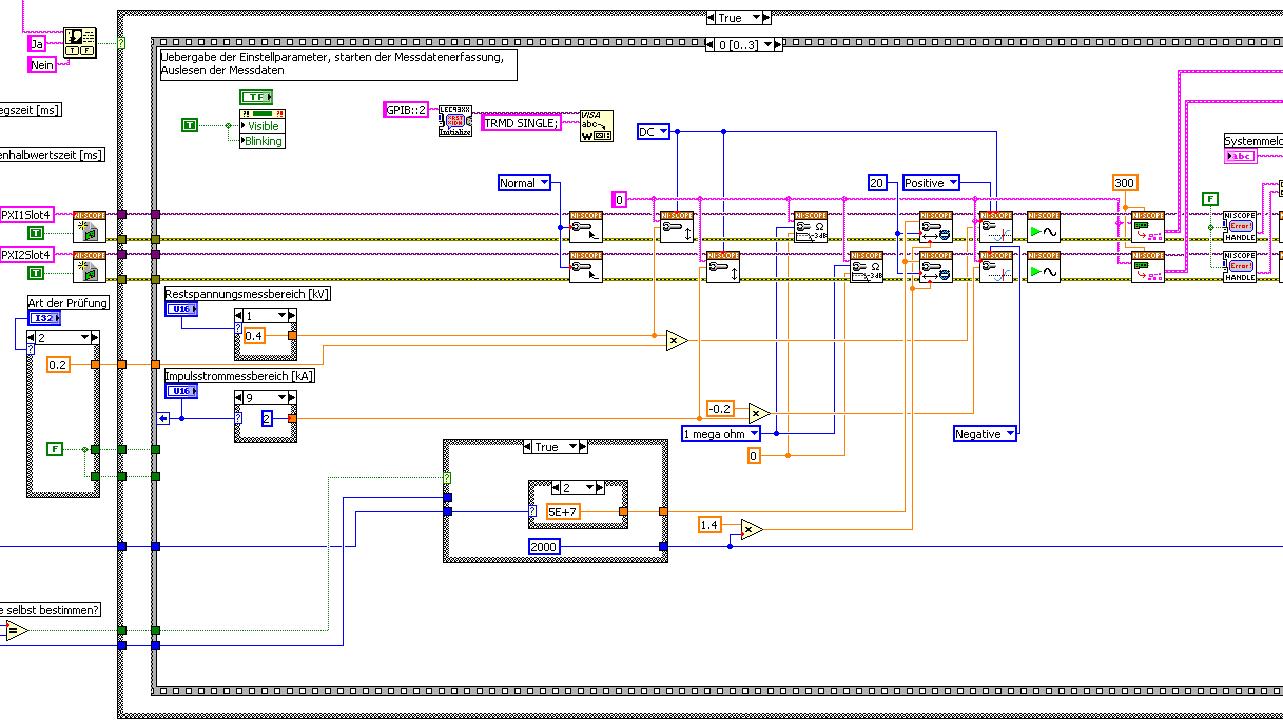
The first picture shows approximately where I started from (sorry I can't post VI, confidential...):
Only the middle part is interesting. Two sessions are initialized and manipulated parallel, trigger too. This has led to delays in the signals and should now be fixed. This apart from the VI works fine.
Goal is to trigger only on one channel but both devices! If possible, the device will trigger must be chooseable.
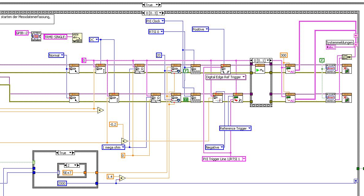
I started to rebuild the VI using the "EX Synchronization.vi 5xxx niScope' seeming spontaneity. The result is shown in the following image:
I tried different RTSI lines, but had no positive results. only the main channel has triggered.
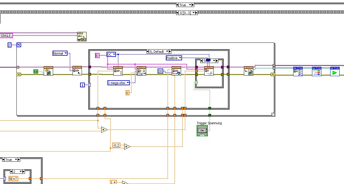
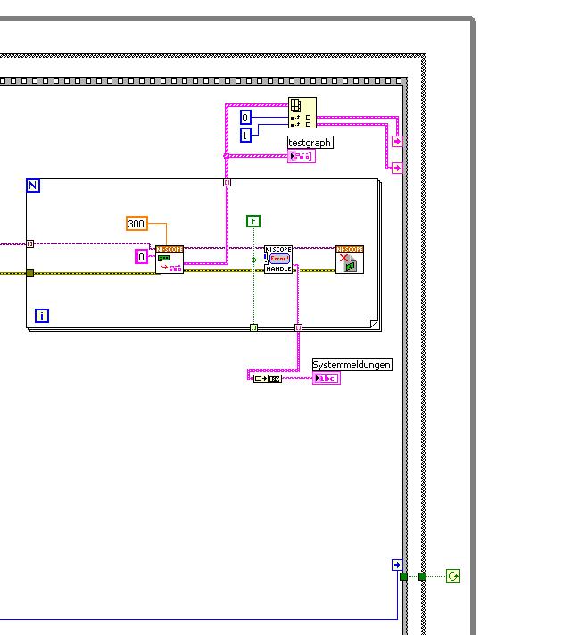
After this first approach, I looked in the "niScope EX .vi multi-Device configured Acquisition (TClk)" and other examples of TClk which seem to work for similar problems. The VI of reconstruction can be seen in the following images:
(Sorry, I had to use two photos..)
In this case, I didn't have no choice for trigger lines, it would automatically set the VI TClk. I tried to trigger on both devices, though. This second approach seemed promising to me, but it was an error:
"niTClk Synchronize.vi:1".
Index (starting at zero) of the session: 1
The error reported by the pilot of the instrument:
No registered trigger could be found between the
devices on the route.If you have a PXI chassis, the chassis correctly identify in
MAX and make sure that it has been configured correctly. If you use PCI
devices, make sure they are connected with a RTSI cable and that the cable RTSI
is saved to the MAX. Otherwise, make sure that there is an available trigger line
the trigger bus shared between devices.Source device: PXI1Slot4
Target unit: PXI2Slot4
Status code:-89125niTClk Synchronize.vi:1
Index (starting at zero) of the session: 1
The error reported by the pilot of the instrument:
No registered trigger could be found between the
devices on the route.If you have a PXI chassis, the chassis correctly identify in
MAX and make sure that it has been configured correctly. If you use PCI
devices, make sure they are connected with a RTSI cable and that the cable RTSI
is saved to the MAX. Otherwise, make sure that there is an available trigger line
the trigger bus shared between devices.Source device: PXI1Slot4
Target unit: PXI2Slot4
"Status code:-89125"
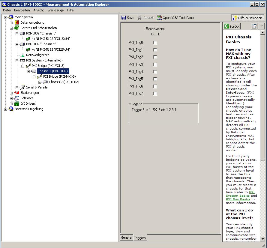
This error came back even after I've identified this drug as possible to the MAX, as shown in the screenshot:
In some of the textbooks, they showed how to get the MAX trigger lines, but as you can see, there is only booking options in my MAX. Whatever I do, I can't find options to define how to get my trigger signals...
In principle, it is possible to trigger instruments in different chassis, which is indicated in this Guide and others... the question that remains is can it be done with my set of components?
I understand that the use of multichassis compromised the integrity of the lines very adjusted as trigger in Star etc., so the configuration should be taken into account in some way, that my approach does not, I knew... But there must be a way to do this? And to start: to get just any signal from one device to the other trigger!
For any advice on this issue, I would be very thanfull!
Concerning
Max1744
Hi Max,.
Thanks for the detailed post and explanations of your application and requirements. You're right using TClk, because this is the optimal method to synchronize the 5122 digitizers. The original VI you worked with is unique for some of the legacy scanners and does not directly work with scanners based on the most recent CMS (for example the 5122). The good news is that you can synchronize these cards to separate chassis, but it will use the calendar 66xx and synchronization (T & S) cards in the chassis of the master and the slave, as indicated in the guide that you have accessed. These are needed because a common reference clock must be shared between them as well as a couple of tripping. MXI itself can not handle export triggers and clocks, so there is no way to do this without physically wiring between the chassis with cards T & S. Unfortunately, regardless of what specific method, you use for synchronization, it will take a material extra beyond what you currently have.
As one of your needs looks like it is necessary to retain wiring between the chassis directly, you may need to consider to synchronize using 1588 or GPS protocols. 1588 Protocol is a system for synchronization on the network while GPS course use antennas and locks for a common wireless signal. Although these synchronization methods may allow you to keep your chassis isolated, they will also require some manual configuration because you would be able to use the TClk synchronization and so the level of synchronization you can get between the cards may not be as good that can physically wire signals between the chassis using T & S cards.
Hope this helps,
Maybe you are looking for
-
A Google page opens and ask my login details everytime I open Firefox. How can I disable this?
Thanks in advance for any ideas.
-
Hello I'm currently under Firefox 8.0. When I go to "About Firefox", Firefox checks the updates and then displays "Firefox is updated" even if the current version is version 9.0.1. How to update? I know that I can download the installer myself, but I
-
These days, Firefox does not completely Hotmail sign
Windows Live IDDisconnection is not complete... You have signed out of these sites: MSN Account Services We couldn't you disconnect from these sites: Hotmail
-
Is there any software available to limit the interference on speakers?
Original title: scrambling over the speakers. I have windows vista and I'm running it on a wireless network that I am picking up a strong radio signal and pretty clearly on my speakers I know not for this kind of interference that I wondered about is
-
Which drive I use to reformat my laptop
Hi I'm trying to reformat my laptop (the State when I bought). I have a number of CD, but none of them said recovery on it. Could someone let me know that I should use please? I tried all the and was expecting a warning on them destroy my data etc