Calendar DAQmx
Hello
I collect the load data and discharge of a capacitor during different periods.
Using the attached circuit, what the best way to define the sampling per channel and I can apply hours measuring without getting the slow operation systems.
Thank you
I don't see an attached circuit. It's a block diagram.
1. continuous samples, do NOT connect to the top the 'number of samples per Channel"on the VI of Timing DAQmx. You simply limit your buffer, which want to keep very large.
2. There is no need waiting for them in the loop. The DAQ reading will limit your loop rates.
3. There is no interest to read this file in spreadsheet each time you an iteration of the loop. Move this reading before the loop. This will speed up your loop a little.
4. set the sampling all that you need for your measurements. The number of samples to read the DAQmx Read should be based on, however many samples you want to process at a time. Just make sure that your code can follow your sampling of data acquisition rate by increasing the number of samples to be read by iteration or lower your sampling rate.
Tags: NI Software
Similar Questions
-
In the application, I need to acquire a sample of 16 channels every 5 seconds.
Currently, the application works when using
1 Daqmx Start
2 Daqmx reading (analog 1DBL N channel)
3 Daqmx Clear and then stop
There is a timer loop that waits 5 seconds before acquiring the next set of samples of conigured table. I am trying to replace this loop of timer using Daqmx schedule vi
My question is if DAQmx schedule vi is used are the correct setting on the next page to attach to acquire a sample every 5 seconds of 16 channels?
Yes, on MAX, this is the equivalent to 1 sample on request and in continuous operation. And Yes, by using the buffer material (DAQmx Schedule VI) would not give any advantage of this. That would be better spent if you do a very fast acquisition. However, for the acquisition of once every 5 seconds, the determinism of your operating system should not be significantly detrimental to your calendar.
Kind regards
-
Output broken for writing DAQmx
Hello
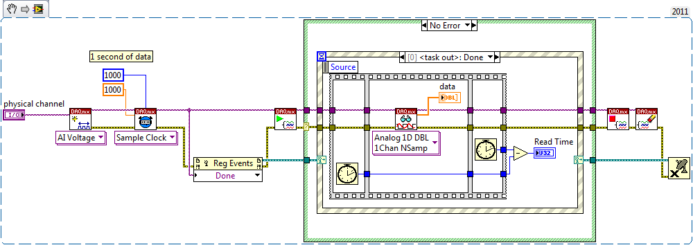
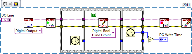
I need emergency assistance with a problem I have with write DAQmx. The 'DAQmx write VI' is located inside a while loop that repeats every 20ms. I use queues to transfer data between several asynchronous VI and the data does not update all 20ms. Because I'm not going to tie the whole project I faked the timing of 20ms to 'Wait for next ms Multiple' vocation. What happens is I will send 20ms of data to the VI DAQmx writing, he will have all the data output with 4ms can sit idle for 16ms. I implemented the task for the DAQmx example 1000 per channel at a rate of 50 kHz, which should take all 20ms to the exit. I also checked the waveforms of entry the entry have 1 k samples and a detachment of the 2nd-5. When I went from the DBL 2D table has not changed. I want to emphasize that all data is sent into the 4 DC. It's confermed visulaly and with the node 'written examples.
I did a test where I hosted my VI to run as fast as possible. In this case, the output was a sine curve, but looking more closely, I found that the output frequency of 25 Hz 5 times faster than the signal that I sent to the writing DAQmx VI. In addition if you limit the loop to 10ms iterate the data is output for 4ms and the idle 6ms.
I know that everything is configured correctly. I rechecked the data I sent you the properties of the task. She should be out correctly, but it isn't. I tried calling support NEITHER and he was not particularly helpful.
The equipment I use is a PXI 6723 AO map. I will attach a vi that anyone could run and I will attach a picture of the exit on an oscilloscope. Thnak you for the help
-James
I solved my problem. I needed to add a calendar DAQmx and DAQmx writing change the task before entering the while loop. I use the calendar to set the mode of the sample and the source of the command, while simple DAQmx writing sends and matrix of zeros. With these added it works very well.
-James
-
samples per channel and the number of samples per channel
in my DAQ mode samples finished program, there are two screws: timing and read.vi DAQmx DAQmx.
I have to set the parameter to "samples per channel" DAQmx timing.vi and 'number of samples per channel' on DAQmx read.vi... Is there a relationship between these two?
My laser runs at 1 K Hz. I want to go to the wavelength, wait for a number of shooting lasers, read the data and move on to the next page...
Thank you
Lei
In your case, the VI will acquire the lesser of either:
The "samples per channel" that you have defined on the timing DAQmx VI
-OR-
The number of iterations of your for loop (N) times the 'number of samples per channel"that you have defined on the DAQmx read VI
The "samples per Channel" VI DAQmx of timing for a finite acquisition dictates how many samples the DAQ hardware should acquire in it's onboard buffer before indicating that the acquisition is complete. "The number of samples per Channel" on the read DAQmx VI dictates how many samples the DAQmx driver must return buffer on board the aircraft to your application.
Let's say the "samples per channel" on the calendar DAQmx VI is set to 50. Thus, the card will acquire 50 samples and place them in the edge of the buffer, then stops. Suppose we have the 'number of samples per Channel"on the DAQmx reading VI the value 3 and what we call the VI in a loop For which runs 10 times. Thus, every time the DAQmx lu VI is called, it will wait until there are at least 3 samples in the buffer, and then return these three. We call the VI a total of 10 times, then we will answer 30 total samples. Thus, the last 20 samples acquired the card remains in the buffer and are destroyed when the task is disabled.
Now let's say that we increase the "number of samples per Channel" on our DAQmx Read VI at 10. VI Read will wait until 10 or more samples are in the buffer, and then return these 10. Thus, we will be back all 50 samples map acquired by the 5th iteration of the loop For. The 6th time we call him VI DAQmx Read it expires, because there will never be another 10 samples in the buffer, and the VI returns a warning.
This clarifies things?
The purpose of this behavior is to allow you to both set the total number of samples that the DAQ hardware will acquire and also control how much of these samples is returned whenever you call the DAQmx Read VI.
Kind regards
-
Hello
I just started using an NI USB-6008 box. At this point, I don't need to fill all the specific tasks other than learning to use the device. I used a fair bit of LabVIEW but never with this kind of material, and I would like to help to understand it please.
In particular, I have attached a VI in which I try to get an analog signal through the USB-6008 and read again (also with the USB-6008 - I wired the pins together). However, I do not understand what is happening when I run this VI. I expect the output a sine signal of 10 Hz for 1 second, 0.1 seconds record and see 1 full cycle of the sine wave. In practice, I read about 10 cycles and constant tension then. Presummably, this means that either the reading continues for more than 0.1 second, otherwise the output signal is more than 10 Hz.
I also tried to use the related calendar DAQmx screws with the output pin to try to adjust the output rate (samples/s) but everything that I've tried return errors. I also tried to open some examples NOR, but these errors returned as well and I still just try things on mine.
Did I miss something obvious here, but any help would be appreciated!
Edit: I had to update this post & attached VI I had made mistakes. The default values on the front panel show what I see after the execution of the VI.
Orbital Hi,
As far as I know, you will need to use the DAQmx Read and VIs write in loops and functions of synchronization to determine data rates you want.
I also did a quick search and found a white paper which you may find useful: http://www.ni.com/white-paper/9541/en/
Kind regards
-
overflow memory for the producer consumer
I'm trying to save data from 4 ports to 40.96 Mhz. using a producer consumer architecture and a PCIe NI 6527 B using an external clock.
I inherited code which works for 2 ports. I tried to add additional ports and changed the size of the data to the DAQ.mx queue and data. Launch the program several times, reach conflicting error messages after less than 2 seconds from the beginning:
Error 200284: Some or all of the requested samples are not yet acquired. [...] To make available samples more quickly, increase your sampling rate
200361 error: Overflow memory device on board. Due to the limitations of system and/or the bandwidth of the bus, the driver could not read the device fast enough to follow the flow of the unit. Reduce your sampling rate.
What is a race condition between the error messages, a problem of timing of start or something else?
I approach, how to debug these types of problems? How can I determine what is causing the error? I can't single step through because I'm at the wheel of sampling with an external clock.
Running on labview 2012 Windows XP on the machine who's 3.17 GB of ram.
Try to reduce the size of your buffer. In fact, simply leave the calendar DAQmx unwired. The size of the buffer must be large enough by default. And then also try to read less data at a time, as data instead of data 500ms 10ms. What I suspect here, it's that the DAQmx buffer is too large and therefore must use the hard drive for part of the buffer, to slow things down a lot.
Other notes here:
1. do not use the time-out to stop your loop of consumer. Your producer should send an order of a certain type to your consumption by telling it to stop. In this case, I would use an empty array. And then, you must release the queue after the loop of the consumer.
2. you want a constant FALSE to Append Array/String input size of the binary file write. This will remove the 2 I32s at the beginning of each table that you write. Eelle are here to tell the size of the table being written. But since you are just data flow, I doubt that you care about those.
3. instead of the entire setup of producer/consumer, have you considered using just the DAQmx Configure Logging VI do DAQmx stream directly to a TDMS file for you? Makes things much faster and much easier on you.
-
How to build square 3 ph pulses and use them to trigger the two analog inputs.
Task:
1) generate continuous 1 Hz ms 45 pulses on three lines of output offset 120 degrees.
Other neighborhoods, three phases (three outputs) 120 degrees out, but instead of sine wave should be a volt 5ms 45 along with a second ground pulse. I need these impulses to control an external circuit. The tolerance of 1 Hz is loose, but 45 ms must be at 100 us.
(2) measure (trigger) two independent DC voltage over 45 ms 50 ms after each front (leader) amount of each pulse. 45 to 50 ms must be 100 us.
Other neighborhoods, begins each measure 45 ms for the DC source #1 and 50 ms for the source DC #2 after opening (rising edge) of each pulse for total of six measurements per second 1 (by 1 Hz cycle).
(3) an analog output must provide ongoing (to be booked) negative DC voltage to be used as a source of supply for external circuits.
I timely when I can generate the 45 Hz by using CO (0) 1 ms pulses continuously and the trigger I (0) on falling edge. I (0) is hard wired to triggering I (0).
How I do HAVE another (1) and two other lines (two phases) and link them to HAVE (0) and HAVE (1)?
Equipment: LabView 8.6.2, PCI-6221 (37-pin)
Hi behappy.
Thanks for posting and welcome to the forums EITHER! I think we can get what you need with the variety of the 6221 37 pins:
(1) our machines of the M series have 2 counters, so you cannot generate all the impulses of 3 of these alone. A solution would be to use outputs digital correlated.
Unfortunately, the 37 pins 6221 has only two IO digital correlated, so you should use a strange mixture of digital meters and IO to implement three impulses. It would still be feasible - for example, you might use a counter for a time base for the digital i/o lines and the other counter to the third output pulse. You would have to match the beginning of the two counters to ensure the phase of your signals.
2) there are essentially two parts to this question, so I'll try to split:
(i) combine the three impulses together to generate a single sample signal out of. I think this would be doable on a different set of M with a higher number of digital I/o lines correlated using change detection (see the user manual of M series). However, at this stage, we are just out of digital lines correlated to use, and I don't think that's possible on the 37 pins 6221.
If you use the 6221 37-pin, which you will probably need to do is to provide your own external circuits OR three pulses together.
(II) get the 5 ms delay to enjoy your second channel. Since you have already discovered that you can sample the falling edge of the digital signal for the delay of 45 ms, you would just add another delay of 5 ms before taste you your second I. You should be able to do this by setting the clock to convert DAQmx frequency (5ms corresponds to 200 Hz). The clock to convert, it's what actually sampling data (keep in mind that the boards of the M series are multiplexed).
To do this, simply use the property calendar DAQmx node, then select: more > converted > rate.
(3) this one is easy - we have not yet used all channels of AO.
So the 37 pins 6221 is a little less ideal because you have not enough correlated digital i/o to make the generation of pulses or change detection - but he has yet to do the job if you can combine the three impulses yourself outdoors and don't mind not using the additional counter to generate the third impulse.
I hope this helps, if you need any help to find relevant examples, please do not hesitate to post in return. Thank you!
-John
-
Hello
I'm trying to control the timing of a timed loop. So far, I have tried several approaches via the software and which worked very well except the time loop in some missed cases 1-2 Ms I want to make sure the timing is right. I tried to provide an external clock through the acquisition of data I. The system I use is NI USB-6212. It has two counters and DIO and AIO, but I keep getting errors. I tried two different approaches. One was to use directly the game 'DAQmx create calendar Source.vi' in frequency mode, and when I did, I got error 200077. Then I found a post of somone saying that sometimes it is not possible and an alternative method is to use the same vi but set task of loop control mode. This one gave me Error200452. For this one you will see in my attachment the suggestion was to use an AI then the moment of him and then use this task for Creat DAQmx synchronization Source.
I don't know what the problem is or if I need to put something differently.
Please let me know if you can help me with this.
I'll try to continue to work on that, but if anyone of you a suggestion I'll be very happy to consider the issue.
Thank you in advance,
Best, Massimo.
Massimo,
In my view, the errors that you see are the result of your hardware USB-6212 is supporting the functionality of the task control loop. I have a M Series PCI card that is capable of operating both of your screws attached without problem (although they still +/-1ms variation on occaision). When I try to use a USB-6212 simulation, I get the same error codes that you do. Unfortunately, it's just a case of a lack of equipment.
Kind regards
-
Mounted daqmx calendar/trigger on 2 chassis mxi-express
I have 2 chassis SMU (including one with a RT controller) connected with SMU-SMU/8384-8381-MXI-express boards.
I can see all the devices in both chassis and can configure DAQmx tasks in each chassis individually, but I can't create any single task with a device of two chassis. When there is a feature of two chassis in the task, I get:
Error-89125 occurred at DAQmx start Task.vi:7220002
No registered trigger could be found between the devices in the range... Make sure that there is a trigger line available on the bus triggering shared between devices.
Is this possible in the software? Or should I add material? I can't find any docs or examples on this subject, other than a promising article on Veristand (ni.com/white-paper/14637/en/, #2) but I can't implement in MAX or NV. Timing is not critical (50 to 100 ms is very good), I just need many devices on 2 sites, so the MXI solution seems to fit in. I thought the solution was to use the local clock on each chassis and set up a trigger shared/exported, but impossible to find something that works.
Thank you!
Hey brimcd,
You are right; It is not a way to send a trigger between chassis without timing card. This link goes into a bit more detail: http://digital.ni.com/public.nsf/allkb/D91582EBF0810F4486256E70004E4145
-
USB6363 DAQmx (reading and writing) calendar seems slower than other similar USB DAQ devices
Hey people,
I have currently a service waiting number with OR the subject, but I thought I'd post up incase anyone has ever dealt with a similar question pertaining to USB DAQ hardware.
Try to understand why there is a difference of synchronization between the 6363 USB and some of the other less expensive USB devices like the 6525 or 6501.

It's a watered the actual code that my team has noticed this difference in the simplified version. The actual code is a reading analog daqmx (it's triggered hw, so we begin the task of analog playback, trigger, wait the time we acquire to and then run reading daqmx. who takes 6 ms to read a single 50 values of the buffer).
Thank you
-Pat
Hi Pat,
Try benchmarking of HAVE it read that way (with the wait timed by the software, it seems to me that the task is probably not yet made to the time you want to read - I guess that the question is relative between the event of the task performed and all the data is available in the DAQmx buffer, I don't have a series of X USB to see) :
Try benchmarking your writing clocked by the software in this way (there no reason to include the check/reserve/validation/start sequence in your writing of reference when the task can easily be launched during initialization of your program):
On my PCIe X Series as the two cases take< 1="">
Best regards
-
I keep me going in circles. I need to understand this because it seems so simple.
I have a digital waveform with a frequency of arbitrary clock. I want to send this waveform on a device USB-6259. I was able to do this with an analog signal and digital signal gives me problems.
For example, if I want to send a 7500Hz digital signal, I need to have the material, since the time of the application appears not to get up to about 1 kHz. But when I try to set up the schedule, it never seems to work. I'm going to make mistakes like that...
"External sample clock source must be specified for this application."
How can I configure things so this thing can clock the stuff at a particular rate. The analog part of the device doesn't seem to have a problem doing this, I do not understand why the digital side needs an external clock.
A modified version of one of the examples is attached.
VI attached
-
Problem with DAQmx Schedule VI (sample clock)
Hello to you all,.
I'm new to this forum, please bare with me. I have some experience with LV, but I am relatively new to data acquisition projects. I use LV2009.
I want to make sure that I use the hardware timing (instead of software distribution) in my project so I followed some of the threads here as sugested to use DAQmx Schedule VI. The problem is that no matter how I set the system I get the same error-200300 invalid calendar
type.The project is simple. I encode with 1000 pulses per
Rev and it is mounted on a shaft of a turbine water goes thru. I'm watching the frequency
and so the rotation of the shaft which tells me that the amount of water flows through the turbine. In the end, there will be 2 channels
by every encoder and ~ 3 encoders (turbines) total and calibrated the main meter that will give me constant impulses and all encoders will be compared to this master frequency.I'll use PCI6602 DAQ, but
now, for the development, I use USB6221. Let's say that the
frequency is between 500 Hz and 10 kHz. What I am doing wrong? Or maybe better to ask - what would be the right approach for this project?Thank you
Marty
Hi Marty,
It seems that your question is already answered here, but Jason is correct that the 6221 neither the 6602 support a clock sampling for frequency measurements.
As Jason mentioned, your best bet is also likely set the mode of synchronization for "implied". This means that the frequency value is sampled at the end of each period of your input signal. In addition, a solution that is clocked by the software (On-Demand) might be acceptable.
X Series DAQ devices allow an external sample clock to use for frequency measures (described in the Manual of X series). Frequency of sample-clocked measures are useful in very specific
circumstances, but it does not seem that you need this feature based on what you've described so far.(621 x) bus-powered M series can also be configured to use an external sample as the X series clock but do you not have the same features described in the manual of the X series.
I hope this helps!
-John
-
Calendar synchronized with Diuble pulse using PCI-6601
Hello
I'm trying to run a PIV of Labview 8.5.1 system using a PCI-6601 map at the exit of the signals for the laser and the camera.
This requires a line for the camera, one for the FPS (first removal of pulse) and one for the Q-switch.
The difficulty is in the need of a double pulse on the Q-switch for mode double frame PIV.
The distribution box that I use is not one NOR one and I don't have access to 3 outputs four against, otherwise, quite simply, I would use a BNC t with two pulses slightly staggered junction.
I have access to a BNC-2110 timing box, but I think it is not compatible with the PCI-6601 and have no funds to buy a BNC-2121 right now.
I managed to create a double pulse by using one of the counters with a finite number of impulses set to 2 and then stop the task, then run this in a timed loop.
However, it is then based on the software, which is not precise enough for the application, and I can't figure out how to get the timed loop to run from the time of 20 MHz of 6601 map base.
I could be missing something obvious here, or perhaps is more annoying? I'm fairly new to DAQmx.
Thanks in advance
Joe
Dominic makes a good point about the operating system, but really the best solution is to use the hardware timing when possible.
I have set up an example that shows how you can implement different sets of impulses finished using the calendar of the Commission. It requires the use of two meters, but then again a generation of impulses finished the fact (on the 6601).
Communities: Generate several Cycles pulse finished using two countersAlternatively, if you have another signal that you want to use to trigger each set of pulses (rather than to specify a rate so that they occur as in the example above), counters on a 6601 are redeclenchables then you can use the external signal to trigger the generation over time and time again without having to stop the task in the software.
Best regards
John
-
Change the sample DAQmx and Terminal configuration mode
Hello
I'm studying 'Timing and synchronization features of NOR-DAQmx' from the following link,.
http://zone.NI.com/DevZone/CDA/tut/p/ID/4322
Could someone tell me how to Figure 2, Terminal configuration entry in the part "DAQmx virtual channel creat? Shoud I double-click on the icon to change it? Or there is some way that I can show it in the block as the sample mode diagram in the DAQmx part?
How can another question, in the DAQmx calendar part, I put "Continous Samples" here? It comes from the function palette? Thank you.
Hi Oly,
To make the configuration of senior year to enter the channel 'DAQmx create' you will need to create a constant or control over this VI either. When you hover over a VI, as the VI "DAQmx Create Channel", you will notice that the dots appear around the edge of the square. "" When you roll your mouse over these points, you mouse pointer will appear a coil of cable/wire how you can right click your mouse and select 'Create' constant ' or 'create' control '. If you create a control, you have a user control in your front, where as if you create a constant, you will have a drop-down list in your block diagram.
It goes the same for continuous samples, simply hover over the VI, right-click on the corresponding 'point' and select this option to create a constant.
In case my instructions are unclear, that I have attached pictures of how to go about doing this, the first is to show 'points' I speak around the VI and the second picture shows the possibility to choose after you right-click on the point.
Good programming!
aNIta B
Technical sales engineer
National Instruments -
Do something in the DAQmx way that does not fit? (Counter triggered on PXI-6608)
Hello
I want to create a counter with my PXI6608 who goes off with an external input, then counts down progressive. I so want to be able to read the County in LabVIEW and therefore to determine the time since the outbreak. I realized this before with the old code, but we know not how to do in the DAQmx way. In particular, I can't create a task because what I want to do seems to be in one of the models of task DAQmx previously envisaged.
Can anyone help? I guess that there is a way to create an 'empty' DAQmx task so I can fill in the details with nodes in property?
See you soon
Lee
You'll want to do a spot of leader board and set the source to be among the bases of internal time using a property node DAQmx (set it before you begin the task):
The feature of cause you're looking for is called a 'start trigger arms' in DAQmx. It is configured via a property node (also before starting the task):
I don't know what you're getting at in regards the DAQmx task "empty." In general, you will use the standard API to define the characteristics and nodes property for more advanced features so you'll end up with a combination of the two. In many cases, you can replace the DAQmx API with knots of property (for a fun example, open the calendar VI DAQmx), but chances are that you might be forgetting something important so I would say always with the screw and then tacking on the nodes property for additional features when needed.
If you use LV 2012, This example should help you get started (or if not, the image still shows you what should look like the task).
Best regards


Maybe you are looking for
-
Hello!I have a problem where the SWF files them won't open in firefox, IE works fine, but not for firefox for some reason which I cannot explain in detail, but I will try with a few photos as aid. https://ImageShack.com/i/exOUUG2vp (Fig 1) If you loo
-
Satellite C650 does not start - error PXE - M0F
Just bought a Satellite C650, get it home and my son decided to stop the whole upward as he ran. Now, we get the error below: Check the connection of the cable!PXE - M0F: Exit Intel PXE ROMNo boot device - insert boot disk and press any key. We recei
-
502-801 satellite: a BT mouse will be working?
Hello I have a 502-801 Satellite laptop with bluetooth.The bluetooth driver is version 4.00.01. Before you buy a bluetooth mouse, I would like to know if it will work on my computer. I searched all over the internet on bluetooth technology, but I'm j
-
Whether I have the service pack 1 & 2.
I would like to know if / what service pack is installed on my computer. I do the start > computer > properties exercise and in the Windows edition section don't no service pack information appears next to the heading of Windows Vista Ultimate Editi
-
BlackBerry Smartphones stopping his ping on new messages message
Is their a way to stop the sound ping associated with the receipt of new messages, both text SMS, Emails, etc. on my Curve 8310 4.5 software Thank you Howard [email protected]