Disorders of PID on a flow controller?
Tags: NI Software
Similar Questions
-
Entered analog PCI 6251 not extent of tension of a mass flow controller
Hey,.
I have a data PCI 6251 M acquisition with a break in Council SCXI 1302.
I'm trying to measure a 0 - 5v analogue output voltage from a mass flow controller (check picture of PIN)
When I measured with a digital multimeter the voltage of the flow signal (PIN2) and common signal (PIN12) I get a stable right tension between 0 and 5v depending on the flow set up. I can control the amount of the charge by providing a data output set point PIN8 and common PIN12 of the 0 - 5V analog signal.
Now when I connect the signal flow PIN2 and on my DAQ signal common PIN12 AI and AIGND, I don't get readings on my labview VI of the AI. In addition the flow does not meet the setpoint voltage, it get stuck in a range of values no matter how I vary the OD 0 - 5V of data acquisition in setpoint PIN8 and PIN12 common signals.
I have to add that I tried different ports HAVE with results of sam, and I also tried to measure my supply voltage with my HAVE and all the good work.
It seems that the entry of AI affects the AO output voltages to my charge. What would cause this? That would be a problem of impedance adaptation?
Management or ideas are appreciated.
Thank you
Ali T.
Update for anyone that might interest you:
I not connected to the ground of the power of the mass of the signal of FJA FJA.
Once I did the acquisition of data reads all data as expected.
So it turns out not to be a problem of acquisition of data, OR at all, but a game of question for my part, as I suspect is the case with most of the problems.
Jeff Merci for your comments.
Ali T.
-
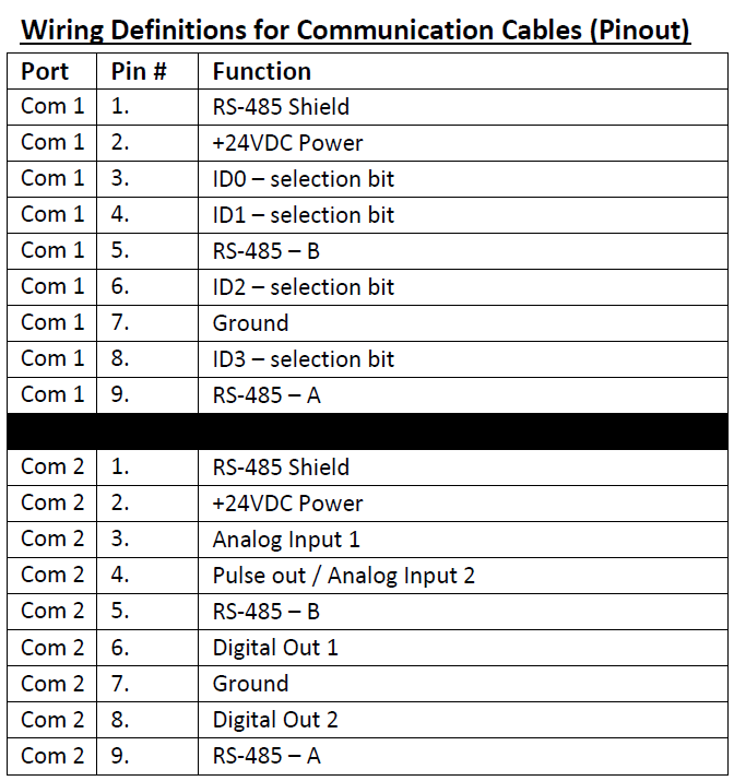
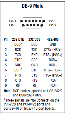
Faced with setting up a connection RS-485 for a for OR cDAQ mass flow controller
I'm an absolute beginner from the ground up tries to connect the port RS-485 to a mass flow controller (MFC) Instruments Sierra for the NOR cDAQ.
The planned route of the person in front of me set up for the connection is:
(1) cable MFC COM1 to Interface Ethernet 4 ports for RS485/RS422 (DB-9 to DB - 9)
(2) Ethernet 4-port Ethernet Interface RS485/RS422 OR cDAQ cable
I'm fighting to understand exactly how the pins should be doubled for the 1st part of the interface. For MFC COM1 pinout is given below:
The pinout for DB-9 male, shown in the quick reference Guide series of NI is illustrated below:
I do not know what pins on the side MFC should connect to which pins on the side of the ENET-485. The manifesto is ground (PIN 7 to pin 1). In addition, I'm stumped. Try to read references online has just served to confuse me even more at this point...
Any help would be appreciated!
Follow-up: I bought a B and B Electronics ULinx USB converter to RS - 485 9 pin as well as a cable of Sierra Instruments. I was able to confirm communications between the cDAQ and the MFC using own Sierra HMI as well as through NOR-MAX provided.
-
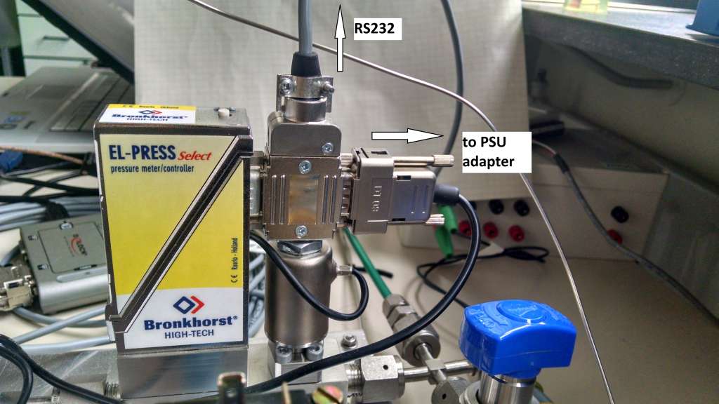
Bronkhorst gas mass flow controller is not powered
Hello
I have connected the mass flow controller of company BRONKHORST using RS232 to USB to my PC connection, but not flashing LEDs on mfc. I don't know if he needs additional power or not? MFC has only RS232 PIN.
I have attached the mfc manual and my labview program
Any suggestion or help would be appreciated.
Thank you
Contact Bronkhorst, you need a special cable that connects the MFC to power and in addition it has a RS-232 cable connection. A RS232 can power your device only.
Take a look at my configuration (it is a regulator of pressure, but is the same for a MFC):
-
To connect to the Net material MKS Alta 1480 mass flow controller
I have a mass flow controller MKS Alta 1480 (MFC), manual of MFC, Labview 8.2 and the NI PCI - CAN card. I know that the MFC wired correctly because I can work using another program on the PC that uses the deviceNet interface. I want to talk to her through Labview. Everything looks OK Explorer measure. I have the range OR DNET. I know that the MACID. I downloaded the EDS of the manufacturer.
Here is what I am missing: a general idea on the DeviceNet interface. Is there a code of example out there that could help me get started? There are tutorials on how to understand the Dnet Protocol? I'm used to control serial--> response devices. I don't know anything about the class, object, attirbutes.
Thank you
Joe
Normal 0
Joe, you can read the MFC object sensor analog-S Flow value.
Class Id 49 0 x (31), Instance Id 1 (0x01), attribute Id 6 (0x06)
The default data Type is integer and units of data's counties
Normal 0 if you want the reading of the assembly object, you're going to have establish polled i/o connection, then read DeviceNet IO.vi allows you to read feeds.
-
Hello
I have question concerning communication with the controller VTEP and NSX.
Will be communicating with workflows VTEP and controller within the network vmkernel management NSX?
Alternatively, it empties the VTEP network? (Network VXLAN?)
I think it is by the vmkernel management network, as ESXi host with controller NSX need not always have
VTEP (or Logical switches) segment.
I thought that it could flow within the segment of NSX controller if it is independent of the normal (communication of host of ESXi and vCenter)
management vmkernel, but I think that there are restrictions which network of the controller must be in the same segment of layer 2.
I tried to find some document but nothing of any document clearly states what network port group transmits VTEP and NSX flow controller.
I'll be very happy if the experts give me answer.
BR
As far as I know: you're right - this traffic is via the host management network and a connection routed between controllers it is not currently supported with NSX - v.
-
I have a flow of stubborn task that I throw like a line-popup dialog box. There are buttons with an action listener. When I use AdfFacesContext.getCurrentInstance () .returnFromDialog (returnValue, null) at the end of the code in the event the message I get is
ADFC 12001: The ADF controller pop tent last entry of error in page flow scope stack.
The error is displayed in the debug window, but does not stop the application or display the message in the application.
I use JDev 11.1.1.7
Everything seems to work, why so this error occurring?
I've seen this error, but no clear answer-related positions.
Hello
seems that the workflow is trying to clean up but there is nothing to clean up. I can't find any entry in the database of bugs, but think it's because the workflow in fact - if present in a dialog online - is not stacked.
Frank
-
Mass flow controller of control using USB 3105 (calculation of the measure)
Hi all
I hope this helps!
-
value of PV in the PID controller may be a string?
Hi all
I'm trying to generate a humidity control using the mass flow controller. I have a USB moisture sensor. The reading of the probe are sent in a spreadsheet and converted string. The value (a string) is used to enter the value of the pv of the MIP? Is it achievable?
Thank you!
Just use one of the chain of digital features.
-
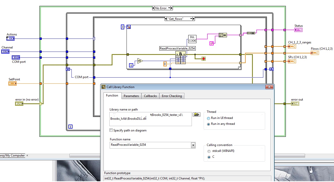
Hello
This post is a follow-up after a few discussions on this product of Brooks. See the previous discussion here:
http://forums.NI.com/T5/LabVIEW/mass-flow-controller-with-LabVIEW/m-p/3245250/highlight/true#M945301
That day I promised when I get 3 flow regulators (GF80) and the regulator 0254, I'll write about my discoveries.
The product looks nice, very robust and good quality before with push buttons and big screen. Got it with a serial cable, so I have just connected to my laptop and began testing the system with 3 MFCs connected to the control unit.
I decided to use the supplied DLL to control the MFC 3 through 0254 unit and also to read the flow, the PVs of MFC.
I did not provide examples of LabVIEW (plenty of flat sequence structures, too crowded, etc.), but he gave a good idea how to call the DLL, what settings should I use.
I implemented a LVLIB including the DLL, a public private Action and subVIs engine for these tasks I need for my experience. Next, I made a main VI only to the objective test, I'll run this VI now for several days to see the stability of the communication, etc... I don't have gas connected to flow regulators, so now, I have only test the communication... So far so good. I have attached the zipped project, including the driver of the lvlib and the criterion VI (it is a VI test, I know that it's not too pretty
 ).
).My experiences so far:
- To read the actual flow of the values of the 3 MFC takes about 1.5 to 1.6 seconds, so I'll use just a 2 sec of sampling time for DAQ in my actual project (in a separate loop, do not disturb/slow down my cDAQ sampling)
- When I started to first test of 0254 unit, my GUI became incredibly unresponsive!
 I took a look at the configuration of the DLL and managed to solve this problem of GUI lag by setting the thread DLL to "any thread" instead of using the user interface of one.
 - If I get later the real flow tests made without problems, I will consider the product as usable. So far, it seems that it will work, fingers crossed
Martins wrote:
rolfk, the llb seems very pro (calculation of checksum is also necessary that I see)! Thanks, I will test it just today, in fact, these are all the features I need: read flow values misses three Brooks MFC and change their values...
I have two questions to your code regarding:
- I see there is an entry "address." Why is it an option (by default, it is not used in your code) in the llb? I thought that this device can only be used with RS232 and RS485 (so no multiple devices in a wreath, so an address would be wise)? Sorry, I read now on the address, it is clear now.
- I wonder about the reason for the digital manipulation of the value of the incoming channel:
- In the Subvi set point, you double the value of channel number
- In the Subvi flow Get value, you double the value and the Decremenet with 1. Why?
Point 1: I only use the address entered in my configuration, but decided to apply in all cases, as it has been documented in the manual. More likely one would need to add it to the Initialize function, the Identification query command. These units can be apparently used in a multidrop facility where they are chained in some respects. Because the client has already had two RS-232 over Ethernet to RS-232 hub ports, he wouldn't try to implement in this way and in further trouble with the wiring and units, such as multi-point communication debugging usually always committed.
Point2: If you read the manual it somewhere says that the channel to read a value from a physical channel must be odd, then to write it must be the same. Do not know what is the logic behind this, but it makes sure the analysis on the side of the camera probably easier that you don't have to look for a leak? to a query or a xxxx = nnnnn.ddddd to update a value but simply to take the channel number to decide if you need to read or write. Ultimately any implementation can be considered to be logic, as long as it works.

Basically the channel to use in the command turns as double the physical channel for the Scriptures and a number less for reads.
As Ben mentioned problems, I had some problems initially with this camera and it could actually be someone from the distributor of Brooks here in the Netherlands that has done something with the units (perhaps an upgrade of the firmware) but it was still a few years ago, and my memory about the details is rather blurred now.
We also examined him to speak the MFC Brooks via their RS-485 interface directly without going through the unit 0254, but which was abandoned subsequently especially because the client had already in another that uses the 0254 and wanted a display to check and manually manipulate the MFC from a software failure. These lab people simply want to have physical buttons to push to feel safe.
Whatever the 0254 navigation menu is a little tricky to operate.
-
Comments and questions about the mixture ADF Page flows with Trinidad UI
Hi all
I did a few tests to see how possible it is to use Trinity to the UI (for compatibility of this stinking IE 6) as well as the ADF Page flows / controller of the ADF. My question is whether there is a sustainable configuration from the point of view of Oracle. I did things to make it work and noted the following interesting behaviors (call anaomalies, if you wish):
(1) addition of ADF Page Flow within the reach of the technology for a project automatically adds ADF Faces. If I try to eliminate ADF Faces of the scope of technology, it automatically deletes the flow of Page of ADF as well.
(2) if I remove the ADF Faces DURATION 11 project library and create a page of trinidad (also set up the renderkit and as appropriate skin and remove a moment-false ServletADFFilter of web.xml) I get errors MDS when running the resulting page. I can't correct the error by removing the MDS libraries either - as soon as I put ADF Faces DURATION 11 library back, things are OK.
(3) since I've faced ADF in my scope of technology, all newly created JSPX pages end up having af:document / af:form tags and have the namespaces implemented for ADF Faces. Not useful if I want only parts of Trinidad, but not a show-stopper, either.
(4) an interesting thing that I have reported before... If I have the ADF Page library flow into my project and then configure navigation case in faces-config. XML (I know, wouldn't do that, just an observation, even if someone who has accidentally library ADF Page Flow in their project without any intention to use the ADF Page flows will find this very annoying to debug...), the first click of button that leads to the navigation works very well. All subsequent navigation requires two clicks on the link/button to trigger navigation. This behavior does not occur if you change the case of navigation to redirect = true.
So, in summary, I seems to be the controller of flow/ADF Page ADF working with Trinidad, with a few minor problems of productivity due to an obvious requirement to have the Library Runtime of ADF Faces and the extent of technology ADF Faces included in my project. Now Oracle - is this going to be a sustainable configuration?
I'd also appreciate comments, suggestions and comments from anyone else who has tried or is trying to use the ADF Page flows / ADF controller with a single user Trinity interface (well, in my case, I'm going to blur more using the tag af:template with components of the Trinity, but it's another whole story).
Best,
John
bump #2+ 1). Adding the ADF Page Flow within the reach of the technology for a project automatically adds ADF Faces. If I try to eliminate ADF Faces of the scope of technology, it automatically deletes the flow of Page of ADF as well. +
ADF task flows have to ADF Faces e around. Not sure this is documented somewhere, but I hope it's
(2) no idea about it
+ 3). Since that I've faced ADF in my scope of technology, all newly created JSPX pages end up having af:document / af:form tags and have the namespaces implemented for ADF Faces. Not useful if I want only parts of Trinidad, but not a show-stopper, either. +
Looks like that is facing an emergency room to have an option in the dialog creation page if create an ADF or page of Trinidad. I'll take a note
+ 4). An interesting thing that I have reported before... If I have the ADF Page library flow into my project and then configure navigation case in faces-config. XML (I know, wouldn't do that, just an observation, even if someone who has accidentally library ADF Page Flow in their project without any intention to use the ADF Page flows will find this very annoying to debug...), the first click of button that leads to the navigation works very well. All subsequent navigation requires two clicks on the button/link to trigger navigation. This behavior does not occur if you change the case of navigation to redirect = true. +
I'm not sure how to restrict we are on the "do not use" them in combination, but to me this looks like a bug.
Frank
-
RS 232 Communication initialization
Hi all
my name is Carl and I have a problem to connect with a mass flow controller. Before developing a more advanced program, I wanted to check the communication and how it works (I'm new to LabView, had no Matlab and Scala so far).
As my simple VI does not work, I checked if a simple RS232 communication tool would work (Termite 3.2). It does so with the following parameters: (IMG_1868)
Parameter Append CR was very important. Then I tried to adapt my VI settings. But somehow, I think I got the wrong setting Append CR. It's a tank of termination setting and 13 of decimal corresponding to return according to the different tables I found in the internet.
My VI sends a text command and read the response of every second. The LED indicates if there is something to read.
That communication works with the tool of termites, that there must be a problem with my VI and the parameters of VISA.
Thanks a lot for your help!
Carl
Carlcarl wrote:
Parameter Append CR was very important.
You must use a property node (written end ASRL) to have the CR automatically added on the written word.

-
Error: The property node (arg 1) in .vi VISA set up a Serial Port (Instr)
Hello
I've seen people once they have gotten this error, but none of them really apply to my situation.
Right now I use LabVIEW example code to read from a device manufacturer. This device is connected using a Tripp Lite USB adapter series (http://www.tripplite.com/en/products/model.cfm?txtSeriesID=782&txtModelID=2430) for the connection from the PC to device with RS232. The adapter works fine when using the software prepared in advance (not LabVIEW) given by the manufacturer and the COM port is seen by LabVIEW. When I run the program, I get the property node (arg 1) visa set up a Serial Port (Instr) .vi (I've also attached the VI but it's a standard VI I got of LabVIEW). I get this error despite the fact that I use the same COM port, who has worked with the manufacturer's software.
I have attached manual of Protocol RS232/debit BUS (not sure if this applies) that requires the device. The device is a mass flow controller whose operating instructions is: (http://nemu.web.psi.ch/doc/manuals/device_manuals/Bronkhorst/917023--Operation%20instructions%20digi...
I'm using LabVIEW 10.0.1
Any help is appreciated
Try to restart the PC and then try the LV version before trying other software.
I have seen thrid party serial interfaces work on the first try but fail when you switch to another application. It was as if the pilot did not know that it was no longer the first process.
Ben
-
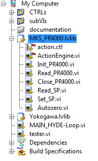
Hello, my question is about HW, manipulation of "best practices".
I have a LV project linking (beside other things) to a checkpoint of MKS PR4000 (it is a digital device of power supply and the reading/controller for pressure and flow regulators sensors).
So far, I have 2 units of flow controller connected to this unit of PR4000. My PC (and my project of LV) connects to the PR4000 via RS232. I have the drivers Web site NOR for the PR4000, all work very well.
For handling easy project that I created my own drivers based on the official drivers, only including the features I need.
I put these drivers in a library lvlib under the project tree. I have an ActionEngine (the scope is private) and some wrapper screws (scope public) to be able to settle all the entries as 'necessary' in the connector pane and to hide the reference, son etc. inside these wrappers. It's also nice that all screws of public lvlib have the same color, easy to find in my main block diagram.
My question: then, I need to expand my experimental rig: I will deploy an additional unit of PR4000 (and connect to the PC via a USB-RS232 cable, since the native RS232 interface is already occupied). What is the 'Orthodox' way to independently use the same drivers for this second PR4000 unit? Since I have already set up the LVLIB for this HW unit, can I simply duplicate the lvlib of PR4000 under the project tree? So I have two lvlib under the project tree: Let's say PR4000_1.lvlib and PR4000_2.lvlib. I could put a different color for the second lvlib and apply it to the screws, so I could easily distinguish public screws which will have the same names. So is this the usual way to proceed?
Thanks for the tips!
Kind regards
Yes, that might work. Do ' Save as ' on the lvlib to a different directory and you should get a copy of all the screws and a new file .lvlib with a different name.
Think about this, what would you if you had suddenly adding 10 devices? 10 copies of the lvlib would you? What would you do if you discovered that there was an error in your VI - you must update every 10 copies of the VI!
A best practice would be to modify your action engine to store several references of the device (e.g., indexed by name (variant attributes are good for this) or by number).
In my view, is recommended for your "driver" be independent of your references of material - so have your screw driver with references, supplied with wire and then manage these references outside your lvlib driver - now I generally store in shift registers in my application. There is a slightly more advanced version of who uses DVR to store references to your material.
-
6008 OR using Labview 8.6 variable output voltage
Hey guys,.
So my goal is to create an output voltage of my USB 6008 OR which can be set from 1 - 5V in Labview. (This output goes to a mass flow controller that varies its pressure based on an entry 1 - 5V) I'm using Labview 8.6 and far I used the DAQ to create analog output of fishing, but I can't figure out how to get a right voltage DC output. Is this possible? Also to measure the output so I connect the cable on the + and - or the + and gnd? Please help me!
The tension of desire is just a digital control.
You should probably just stop and take one of the free tutorials. A digital control is a very basic concept.
Maybe you are looking for
-
AppleScript-> Get contact photo-> NSImage
I hope that red_menace or ASObjC another expert will see this. In collaboration with AppleScript, I have: tell application "Contacts" set theImage to image of somePerson end tell
-
How can I activate the automatic out-of-office reply in e-mail?
I want to turn on holiday email or response from the Agency.
-
Pavilion 15-au027cl: I would like to put an SSD in my Pavilion 15-au027cl.
I would like to put an SSD in my Pavilion 15-au027cl, is it possible? If that is what is most campattable MFG. ?
-
HP OfficePro 8620e: cash-back on printers - HP officePro 8620e
I ordered the above printer with a well known distributor of Yorkshire. I noticed that advertising claims when buying I can get cash of £60 return of HP. Looking at the HP site, it says that the expired cash back the last day of July 2015. That steme
-
Adding RAM to HP Touchsmart laptop 14-b109wm (REF E0X70UA)
Hello! I need to update my RAM on my HP Touchsmart laptop 14-b109wm. I'm on a virtual OS on my laptop via Hyper-V. In doing so, I'm running out of RAM available. I find myself trying constantly to adjust the amount of RAM in my virtual Session. I th