engine measures DC
Dear ppl.
Need help to defame readings of voltage oscilloscope, torque, angular and contre-electromotrice of the attached circuit speed.
The engine is a hand-driller of 550 watts.
Mutual inductance A - F, the inertia of the shaft and friction are set by default and unknown.
The other settings show its real values.
Can I convert Nm rads x seconds and Volts volts directly?
These logicals values or outrageous?
Thank you very much.
Hello danielsoy
The first thing you need to find is the relationship of voltage (or current) with a couple. He thinks that West is an education that relates to current and torque. Then, knowing the torque and inertia shatf you can give the angular aceleration of wheels. A numerical integration, you can calculate the angular velocity of the wheels. That s how you can address the problem. With an encoder, it would be much easier, because you can measure the angular position, speed and acceleration and with acceleration you can give the couple.
I hope that this information will help you.
Tags: NI Software
Similar Questions
-
Movement, measurement and time between them
Hello friends,
I have a doubt with my program. I made a statemachine (using the 9.0 lab, which is not possible to use a new) to move two motors and a measure of the (curved). Move engines measurement is performed, and this measurement is done in the same time Motors move, why?
What should I do? I want the engines move, and then do the measure, when this is done, then move the engines again and so on.
Any idea? Any help is appreciated.

Attached you will find the program (sorry because of the drivers, they are Thorlabs for engines and Keithley 2400 for the measure)
-
use of crypto engine - how to measure?
Hello
I'm looking for a command or another way to measure the CPU usage in a card crypto engine?
Is it possible to check how the vpn tunnels crypto engine effect processor traffic? Why I need? For example if I had 100 tunnels with certain characteristics of traffic, I need to know if I can add new tunnels it or I need to buy a new router to put an end to any new added VPN.
SNMP OID? command?
I tried to find something, in reference to the command, but without success.
concerning
Przemek
Przemek,
I am afarid the answer still will not be uniform :-)
In your case, you run embedded cryptographic engine (or at least what I remember of NETGX).
IKE sessions will be processed by the processor and only IPSec flows processed by the encryption engine.
More than sessions IKE - more stress on the control plan. That is to say that the CPU high can still affect even if engine cryptographic tunnels is relatively inactive.
You might get some indication at the beginning of 'show crypto isakmp stat' but actual counters to monitor will depend on your configuration.
There is also a finite number of sessions can be sent to the crypto engine.
From a realistic point of view, you should follow the sheets (marketing) insofar as the scaling of goes.
Marcin
-
Move the engine and perform a measurement (thorlabs motors and drivers)
Hello world
I was just born in this world of Labview and I m quite lost. I´ll explain my situation:
Queue BEFORE the start of the measurement time is something that you must do it manually because it is up to the user.
Until how long to wait for the measurement of complete, the manual includes many examples of the use of registers and implements buffer to find out when the measurement is finished using a linear scan (this is how I do it). The idea is to set buffer equal number of datapoints (say 100 on your beach IV), ask what to measure (current, voltage, both) and the records to see when the buffer is full (say all 100 to 500 ms) election. Let the keithley 2400 settle tensions for you on the specified range and returns the set of data, once completed.
As far as when the movement is finished, you will have to see if there is a way to detect that your equipment (stick otherwise with the late pre programmed). If they are lit IV measures, you could do the following. The ABSENCE of any power source and measure the current. Check periodically after the movement commands are sent. Once you measure a current, the CDC for the cell, you must contact.
For data storage, use the shift on the state machine itself registers. Erase the registry when starting an analysis, then insert each measure if it is taken (table 2D or array of clusters). Another possibility is to use another while loop to back up data (a consumer) with the data being past in a queue and added to the file after each scan (this will help if you are concerned about breakage resulting from data loss). After each measurement, queue the data to a queue managed by the consumer. (you will need to keep track of which file to add data to).
-
issue of engine/table of measures
I do I'm sure that there is a mistake that is easily corrected. I'll make a motor of action where I need to add to a table of the elements and after that the table is full, throw away old data and add new data. If someone can tell me why this table continues to be all zeros, I would be happy. Probably a misuse or misunderstanding of one of the array functions. If someone could put a picture of the VI corrected rather than tie the real VI it I would appreciate it that I won't be on a computer with Labview until Monday. Thank you.
One problem, it's that you insert in a position that keeps incrementing with each round trip. So, you have a table of 15 items, but eventually insert in position 16, 17, 18... These are positions that are not defined. If you do something where you insert the new element at the top of the table, then you must always insert in position 0. If you are still wanting to put at the end, you add at the end of the table and take a subset of the table of index 1 for the length of 15.
The real problem, that we never see anything other than zeros, it is that the wire goes into the shift register to the right is the same one that comes out of the left. Changes that you make by inserting into the table and taking the subset disappear with each iteration of the action engine and never reach the table indicator
-
HP Officejet Pro 8600 n911a: HP Officejet Pro 8600 n911a engine Pick blocked error
The printer is not picking up the paper in the tray. It sounds as if she is about to do, but the end result of all that turns, the error message "Engine Pick off". I turned off the printer and also disconnected/reconnected it. None of the measures "not won" the engine Pick.
Does anyone have experience with this problem or a solution?
Hello printbuddy112,
Let me direct you to "Pick" toubleshooting guide motor at a standstill Hope this helps.
http://support.HP.com/us-en/document/c02920174
Kind regards
Bryan
-
Installation of bench beginner for the introduction of analog measures
Hello world
I'm looking to install a system to help make some simle measures. This configuration will be used only by me at my desk/Workbench to help me better understand some parts of machine, that I as well as various other hardware troubleshooting. The I want to be able to take common measures are: stress/strain, vibration, temperature, force, torque and movement.
At this stage, this project is on a small scale. I'm not running from PLC or using data in order to operate a plant. This configuration will be about just myself, my computer and a piece of equipment, I need to test.
I currently have one 6003 NOR for my use that would be preferable to use, but if I need a stronger DAQ so I can get to the need.
My main question is if I can get aqeuate with hardware DAQ 6003 and results if I would be able to condition enough signls accompaniment or if I need a DAQ with higher resoluion and a signal conditioner sufficient. My concern is whether or not I will be able to properly signals on status of piezoelectric sensors at vibration action. Is there a way to produce viable results, or I'll have to come back a more capable DAQ? I wish I could do an analysis of the frequency on trees engines operating normally at about 60 Hz. It would be nice if I had the Betacam to observe signals of up to 150-200 Hz at least. In my case I don't need extremely accurate results if I can go out with an afforable configuration more. I think that a level of trust of value p final (90%) will go well at this time.
I'm still quite new to data acquisition and signal conditioning. My purpose behind this, especially to learn how to take the right steps correctly more than I worry accurate results.
If someone could give me their thoughts about this I would be very grateful.
Thank you kindly,
James
James
I think you need to split the signal conditioning in data acquisition. I suggest you watch the series 7B Analog Devices and some of the imitators, for example Acromag.
http://www.analog.com/en/products/landing-pages/001/7B/7B-Series-Overview.html
Essentially, you choose a module specialized for each measure of your choice. The modules are isolated, at least reduce signal interference problems. Sensor excitation, e.g. for the strain gauges is provided on certain modules. You will need to study the performance of frequency to get the 200 Hz on some modules.
The modules plug in a motherboard that can then be connected to any data acquisition system that you like.
Or the versatile NI9219 can better meet your needs.
-
Engine for MyRio adapter command 2 DC motors
Hello
I have a question about the adapter engine for the MyRio. I found the following code example:
https://decibel.NI.com/content/docs/doc-45592
This afternoon, I was able to drive a motor continuous using this VI, but I want to use to control 2 Motors continuous. I tried the following (see photo) and it did not work.
What should I do for the second DC motor?
Thank you!
Hello
Well, the next time you post, it would be useful to have all the information to start with (what does your system, errors, measures
you have taken to solve the problem, etc.). This way more people will respond and we can help you more easily.
By parallel loops, I just run two processes in separate loops at the same time in the same VI (what they do on the link).
If you think about it logically if this initial process is running one engine, then do the same exact process but that it points to the
second motor will run the second engine. So, if you include the two pieces of code (exactly the same but different engines references) in the same VI then it can run two engines.
If you look at the link I have attached before she speaks of two ongoing processes at the same time within the same VI.
You can then use queues and the authors of the notifications (look in them) to communicate between the two processes you use, allows from Control Panel even before to control them and stop them both at the same time.
With this, you should be able to all both enforce.
Hope this helps
-
Measure the voltage of strain gauge
I have connected my 9237 to a 9945. I use a 350 ohm strain gauge. I have the voltage set to 2, 5V Max is there a way to measure physically to be sure that it is 2.5V? Also, in my vi I use a DAQmx create function of the channel. I want to add another channel for this but can't see how to do it.
Thank you
HS
Hi, Harry, it's Paul with engineering Applications to the OR.
My first question is why you are wanting to physically measure the voltage?
If you are wondering how that tension may vary, it is limited by the maximum capacity of 150mW of your device, as explained here: http://digital.ni.com/public.nsf/allkb/7CBC67482CC9FB318625758C0048FF73?OpenDocument
If you want to continue to measure externally, you have a few options. You can use another DAQ hardware to measure the voltage, or you can use another external device, like a digital multimeter.
If you want to see in the excitement that is actually supplied LabVIEW code, you can use the node property DAQmx 'Value of real excitement'.
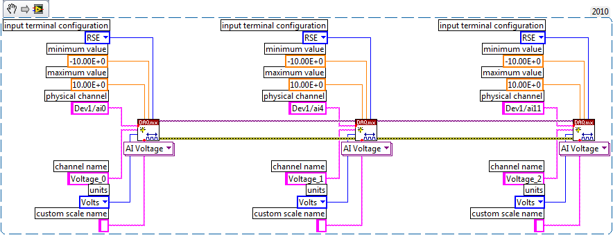
As far as playback of multiple channels, theres two ways you can go about it. If your channels are sequential and all have the same settings, then you can change your name of the physical channel to something like 'Dev1/ai0' to ' Dev1 / ai0:3: to specify the first 4 channels.» Alternatively, if you wanted to select non sequential channels, you can chain create channel set tasks, as long as they are of the same type of task (AI voltage, etc.) and the same device, as shown below.
Let us know if you have any other questions.
Kind regards
Paul
-
There is no chance to install a standalone engine shared Variable of EVS?
Hello!
I wrote a small application that reads the values of a NetworkVariable created on the local computer. The address of this variable is something like \\127.0.0.1\System\test1
That I can see, I can use this type of variable (I mean System -based) that if I installed an EVS (by Measurement Studio). But to install Measurement Studio, I need too Visual Studio...

There is a way to work properly with NetworkVariables based on a system without having to install everything as I said before? AES is responsible for the correct operation of NetworkVariables? In this case, is there any chance to install a standalone engine shared Variable of EVS?
Thank you!
I found the solution to help NI MeasurementStudio 2008:
Server deployment
In this scenario, you must deploy the motor Variable shared to another machine that plays the role of the server. To deploy the shared Variable engine, you must run an installation on the target computer. The required Installer is installed with Measurement Studio for the [InstallDir] \ Redist\NINETVARSERV folder.
You can view all the command-line options to run the installation program with
setup.exe /?. Command line options, you can choose to run the installer in silent mode.You can use the Variable Manager to create and configure network on the server variables. The variable Manager is installed by default. To run the Setup program without installing the Variable Manager, run
setup.exe /prop VARMANEXCLUDE=1command. To run the installation program of engine Variable shared in silence and without the Variable Manager, runsetup.exe /q /acceptlicenses yes /prop VARMANEXCLUDE=1command. -
measurement of current with usb-6009
Hi, my name is hung and I am a student in electrical engineering... I'm doing a thesis that the project using Labview and acquisition of data NOR UBS-6009 to simulate the function generator, Oscilloscope, Digital Microsoft (DMM)... and now I'm simulating DMM. I managed to measure the voltage and resistance which i use voltage divider method, but I encountered a problem with the current measurement. The problem is the USB-6009 to measure use the current, it measures an incorrect value. I tried to use the current CQI 0-20mA Sample.vi example but it always measures an incorrect value. If NI USB-6009 supports for the measuring current? Is there a way to measure the currents using USB-6009? Please, help me. This thesis project is so important for me. Thank you.
Hung,
Since you are a student in electrical engineering, I'll show you how to know the answers to your questions.
1. review the specifications for the USB-6009 case. In particular look at the specifications of analog input.
2. How would you measure current if you had only a voltmeter? Use the same method with the USB-6009 case. (Tip: apply the Ohm's law).
General comment: when using any measuring instrument, always consider maximum permitted values at the entrances so that the instrument is not damaged
and the measure is accurate.
Let us know how you do.
Lynn
-
All,
I have a cRIO-9068 I try to use the scan mode for. I have intalled all the latest drivers and software as explained. However, when I put my chassis to scan mode, then select deployment all, I get this error on my chassis and all my modules:
"The current module settings require a NI Scan Engine support on the controller. You can use Measurement & Automation Explorer (MAX) to install a software package recommended NOR-Rio with NI Scan Engine support on the controller. If you installed LabVIEW FPGA, you can use this module with LabVIEW FPGA by adding an element of FPGA target under the chassis and drag and drop the module on the FPGA target element. »
Everyone knows this or know why labVIEW does not recognize that the software is installed on my cRIO or is it not installed correctly?
AGJ,
Thanks for the image. I saw a green arrown beside all my pictures of chip and it seemed that meant that the software wasn't really being installed. I formatted my cRIO and did a custom install. My problem was that I had the two labview 2013 and 2014 installed and the cRIO put conflicting versions of software. After doing a custom installation and choose only the versions of 2014, my picture now looks like yours!
-
Well, this is embarrassing, but I can't understand this. I just installed LV 2010 distribution one OR supplied disk. All updates were then applied automatically through OR on the web. In the palette under measure i/o functions, the only option listed is NEITHER Scan Engine, there are no icons DAQmx. It's almost like DAQmx is not installed, BUT on the panel controls, I can choose the physical channel can put on the FP. I also have LV 8.6 installed and everything is normal there. I have a USB-6008 installed and it shows and test M & A OK.
Thanks for any help!
Alan
I don't know if you have device driver CD OR, since you can just use it. Otherwise, go to http://www.ni.com/drivers/ and install the DAQmx driver.
-
Measurement Studio for purely GUI using?
Hi all
I find graphical LabVIEW + fantastic approach to the acquisition, transfer and processing of data from data flow programming. The façade is also ideal for stand-alone single screw, or quick hacks to try a code.
However, when it comes to creating a professional quality for a large application GUI, I find offers of tedious LabVIEW and strains to use. So far, I used objects of façade regular, XControls, event structures and property nodes.
I am now looking at Measurement Studio. Here's what I think:
- Implement business logic in LabVIEW (compiled as a DLL)
- Implement GUI in XAML or C++ - primarily use native Windows elements, but bring in the Measurement Studio controls a graphical representation
Is this a viable, reasonable approach? Is there a "witch hunt" s that I should look out for?
Thank you!
Hi JKSH,
Everything you described should be possible that LabVIEW can create DLLs and assemblies. He may ask you to register an assembly that is added to your project so that everything works correctly when you compile. In addition, you must have LabVIEW Run time engine (RTE) installed on the machine that you are running the application on. If this is the same machine that LabVIEW is installed, you should be all set and if not this editor is available on our website (ni.com/downloads).
-
Error-201314 whenever the engine killed
Hi guys,.
I'll build a test bed that takes a few smaller engine size measures. I use the 9188 cDAQ platform and a module in the series C 9401 to get the signal of an encoder that is mounted on the engine. Whenever I kill the engine I get code error-201314 saying the following:
DAQmx error: sampling Multiple clock pulses have been detected within a period of the
input signal. Use a sample clock rate that is slower than the input signal. If
you use an external sample clock, make sure this clock signal is within the j
Itter and voltage level specifications and seedless.The way I have the configuration of the task, it's pulse tachometer to act as an external sample clock and charges against the edges of 20 MHz clock, so I can hardly believe I'm getting any type of engine accelerates faster than the clock of 20 MHz. Anyone has an idea what this message means? So, I wonder if I need to be more careful about the way my reasons are connected.
Thanks for the help,
Ryan
Hi Ryan,
Small defects on the edge rising or falling of your tachometer signal could be picked up as additional edges. I suspect that the Act of powering the motor is presenting the noise on the line, whose meter is picking up as the edges in double during transitions.
The 9188 she supported for digital filtering on the meter inputs - introduced feature in DAQmx 9.4 for the 9188. You can use the digital filtering to reject any pulses below a certain duration. From your description, it seems this would be a likely solution to the problem.
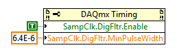
In LabVIEW, you can define a digital filtering of the sample with a property node DAQmx Timing clock signal:
If you use a different API and ill have to find the equivalent property do not forget to let me know. Remember that if you use a version of DAQmx before 9.4 you will need to update your driver to have the feature available for your 9188.
Best regards
Maybe you are looking for
-
How to restore an album to my music which was deleted and bought in itunes
I deleted an album from my iphone on the assumption that there is in my music on my computer in itunes. It no longer appears in my music and I followed the instructions found on different sites for the "low loading of previous purchases from the itu
-
iCloud music library playlists can include music from your music library to iCloud. This playlist cannot be downloaded, because it includes other types of media or songs that are not eligible. What does that mean? I have iTunes game and not really en
-
I've already purchased and downloaded Acrobat 8 Standard and need to re - download and I can't find a way to do it.
-
HelloApparently I can store photos in the cloud as part of my account with Adobe. But I can't find anywhere on the web site of Adobe how to proceed. Can someone point me in the right direction please?Thank you very muchSteve
-
I try ,i in the plans & products click on the map button to manage, but no plan Cancel button.Can I try other think to cancel a subscription in Dreamweaver CC ?