Event_Change relaxation
OK, so my previous question on unchecking and checking a box does not accomplish what I wanted to do. I wanted to trigger the event_change on the object checkbox. So, basically, I need the code to invoke the action event_change programmatically.
Thanks again
You can trigger an event on an object any using:
objectName.execEvent ("the event name")
In your case, the event name is 'change '.
Paul
Tags: Adobe LiveCycle
Similar Questions
-
A movie for relaxing family viewing. It was not evaluated and which seemed to be a good family movie. Not 5 minutes into the film, we have made the language is insulting to us and turn it off. Can we delete this movie rentals and choose another?
Contact iTunes Store Support.
Contact info varies by location, but you can find it at the bottom of the web page of the iTunes Store.
-
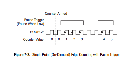
How to generate a single Point (On-Demand) edge counting with relaxing break
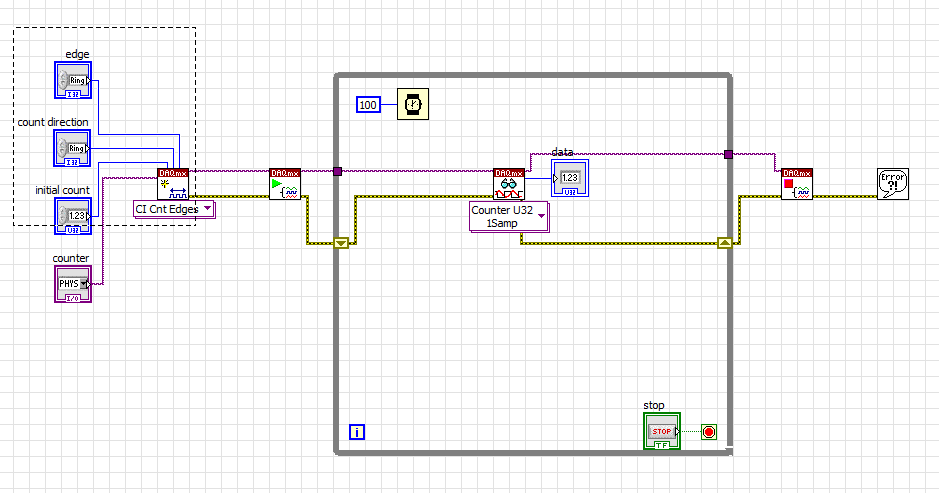
I have problem when creating a Labview program to generate a single Point (On-Demand) edge counting with relaxing break illustrated in FIGURE 1 below. I only know how to build counter edge without relaxing break and my program is illustrated in FIG. 2 and gaskets also. Should what changes I make on my program? The DAQ card that I use is 6259 PCI/USB.
FIG1. Single edge counting with break Point (on request)
Fig.2 my program to generate the edge without relaxing break
It is resolved
-
How to synchronize the start of IT and relaxation the Scan list (DAQmx Switch)
Hello
I want to measure samples of N to the AI0 of Council NI PXI 4461. The measurement starts on a rising edge of a digital triggering provided to the PFI0 of the same Board. The measure is configured with samples of N/2 pretrigged. So far, everything is under control...
Using an NI PXI 2567 Board, the signal applied at the entrance the 4461 (AI0) switches between a V2 and V1 signal. I would like to synchronize the switch between the two signals with the trigger signal applied to the input of the PFI0 Governing Council 4461. In order to obtain samples of N/2 of V1 and V2 samples N/2. Synchronization of 1 to 5 ms would suffice!
My question is how to synchronize the start of acquisition of AI pretrigged of 4461 with the switch control given by the Council of 2567?
Thank you in advance for your help...
PS: the configuration of the system is:
-LabView 8.5
-Chassis PXI-1044
PXI-4461 on slot 2
Module 4-slot PXI-2567
Hi Frederic,.
I came back to this recently and used the following examples to run the desired synchronization.
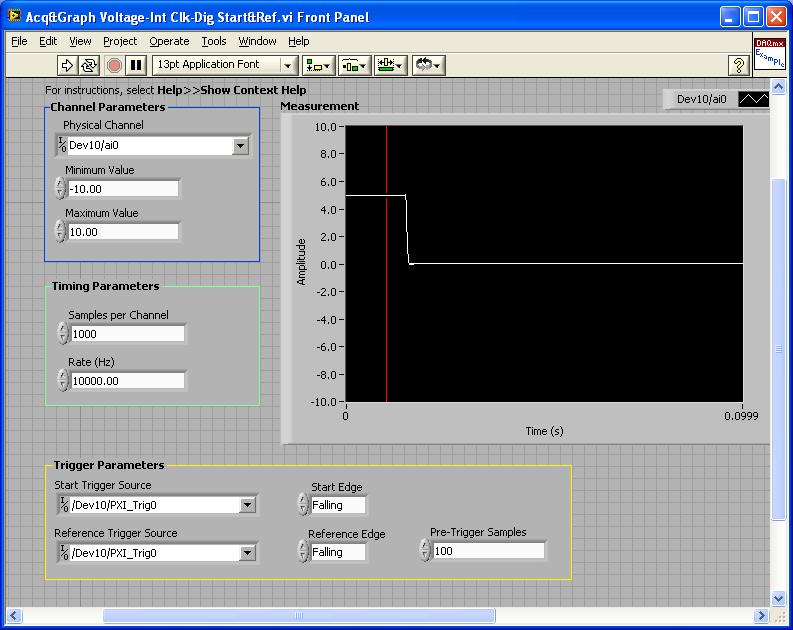
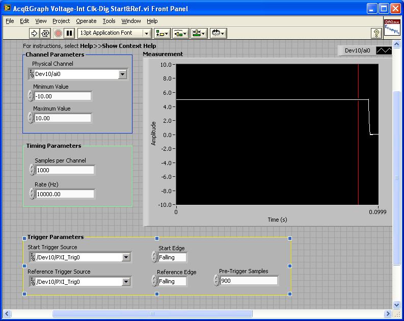
PXI-4461: Acq & graph tension-Int Clk - dig Start & Ref .vi
Samples per channel = 1000
Rate (Hz) = 10000.00
Start the trigger Source = / [name of the instrument DAQmx] / PXI_Trig0
Onboard start = fall
Reference Source Trigger = DAQmx Device Name] / PXI_Trig0
Reference edge = fall
Trigger samples = Variable (100, 500, 900)
PXI-2567: Switch Scaning-SW Trigger.vi
Advance the output terminal full = / [name of the instrument DAQmx] / PXI_Trig0
Scan list = / [name of the instrument DAQmx] / ch0-> com0.
Scan list = / [name of the instrument DAQmx] / ch1-> com1;
Hardware configuration:
The PXI-2567 module controls an external relay that switches between the voltage of 5 V on ch0 and ch1 0 V.
The PXI-4461 connects to the COM of the external relay and therefore reads 5V when ch0 is connected; 0 v when ch1 is connected.
Procedure: The above examples are used in the following procedure.
1. run the PXI-4461 VI. A start trigger (falling edge) is necessary to start collecting samples before firing.
2. launch the module, PXI - 2567 VI. When ch0 is initially (and immediately) on com0, a trigger is sent to PXI_Trig0. The PXI-4461 will begin to acquire samples before firing.
3. - click on the "Connect to the next" button on the front of the PXI - 2567 VI module. This sends a trigger to entry software for the PXI-2567 module and the transitions of the scan for ch1-> com1 list. Once the PXI-2567 module remains (debounced), advanced complete relaxation is sent on PXI_Trig0 for the PXI-4461. The PXI-4461 will begin to acquire samples after outbreak.
Note: Instead of the trigger of the software entry, an external input trigger can be used (e.g. PXI_Trig1).
Results:
> Before instant release of samples = 100
Delay is caused by the time of actuation of external relay.
> Before instant release of samples = 500
Delay is caused by the time of actuation of external relay.
> Before instant release of samples = 900
Delay is caused by the time of actuation of external relay.
I hope that the attached screws and the explanation above helps you and/or other customers who have this problem.
Best regards
Chad Erickson
Switch Product Support Engineer
NOR - USA
-
Acquisition keep repeated samples Source of relaxation
Hello
I found this article http://zone.ni.com/devzone/cda/epd/p/id/5009, and the vi attached to it will do what I need. I want to acquire continuous samples at a sampling rate specific based on an external trigger on PFI0. Pretty simple things. However, the trigger on PFI0 signal repeat at regular intervals (every 0.1 seconds or more). I want the vi to acquire all the time but to be triggered on the first instance of the trigger on PFI0, then to ignore the rest of Extensible triggers. It may acquire up to 10 seconds after this initial trigger, and after the time has expired, that I will call the DAQmx clear task vi.
The vi of this article will do this, or should be changed in any way to accept only the first instance of relaxation?
Thank you.
Steve
You're in luck. In response to the 1st relaxation and ignoring the following are normal behavior by default. On several occasions of the additional work of trigger (and CQI data compatible hw) to set up.
So yes, the trigger in the article you linked should work as you want. Note, however, that the example is designed to use an external signal like a sample clock. If you just want to use the synchronization engine internal to the Commission for a specified sampling rate, you can specify "OnboardClock" as the Source of the clock on the façade.
-Kevin P
-
Outbreak of several sources of relaxation?
Hello
I have a system with four ADC inside PXI. Also, I have four sources of relaxation one for each card.
In some plans, I need start the ADC cards simultaneously by using this triggter which comes first. I don't know which triggers will be first. Y at - it means to achieve in LabView?
Thanks in advance.
Hi Podoba,
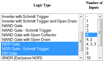
The 6123 does not support the detection of change, so the best course of action is probably to use an external RC (or NORMAL) door with 4 inputs. You can connect your signals to the doorways or, and then use the signal to trigger your DAQ hardware. If you use a NOR Gate, then you would trigger on the falling edge.
The "additional material" is really just a simple IC. You will probably find something that meets your needs on digikey (search example below parameters):
Best regards
-
Hello world
I am a beginner with LabView. I'm able to acquire several analog signal of my PCI 6221 using DAQ Assistant, but my requirement is to measure only all my entries with relaxing break for example I need to acquire data only when my example PFI10 is Hawaii. Whenever the PFI10 is Lo, the break of the measure.
I found an example to reach the break here. However, it is only for 1 channel unfortunately. I do not understand about the flow, but I tried several times to add another channel to my purchase, but without success. Maybe my knowledge is limited and only able to start the project of the DAQ Assistant, but not this type of project.
I tried to add another channel to DAQmx create Virtual Channel.vi but he couldn't accept two inputs. Maybe I need some kind of multiplexer?
If the question above can be done, how do I add another measure DAQx Read.vi inside the while loop?
Can someone tell me how to add channels (I need at least another 2 analog channels) on this vi? I think, any other user who are in the early phase like me will all benefit your respons.
Sincere greetings,
Hague
Hello
Found the solution (vi attached). But it is only from 2 channels.
Kind regards
Hague
-
How to stop the acquisition with a relaxation with the NI PCIe-6323
Hi all
I wonder if it is possible to stop data acquisition or pcie-6323 with a trigger pulse the same way that I begin to acquire samples with a finished sample mode trigger pulse.
Thanks in advance
M.
The samplesPerChannel that you can show what the sample clock configuration defines the total number of samples for the acquisition of finishes. In your case, you will read the data previously triggered so permanently in force this setting really only sets the size of the buffer. If you want to just be large enough to avoid overtaking (although...) If the window you buy is potentially very short, you might want to explicitly configure the size of the buffer to something bigger and maintain the value of samplesPerChannel down so that the reference trigger can be accepted earlier).
The numberOfSamples you specify when you start the player defines the number of samples for the next call for reading. If you can read the small windows of streaming data to avoid having a blocking with a large timeout call. If you do not want to change the time-out period, it is a property of the DAQStream class.
The "continuous" examples (e.g. this one) should show how you can read back data asynchronous as it is acquired. Your configuration looks more like a "continuous" example
Since you want to start and stop using the same line as the trigger, perhaps an alternative to the evolution of the default read pointer would be to set up a central task of analog input with a relaxing break. The caveat to this is that the break does not stop at the task and as soon as the line goes back to you will begin to acquire the data again - I would say using a meter to separate groups of samples in the buffer zone continued. If you wish to purchase multiple windows of data in short succession well, then I would go with that instead to avoid having to restart the task (and potentially Miss samples during the restart of the task).
Best regards
-
DAQmx: With relaxing break pulse blocking
I have a NI 9401 module in a chassis 9171 and stand at the door of the output of a counter with the release of another counter. 1 meter (the signal to be blocked) generates a 3 Mhz signal and meter from 0 (the door) generates a 10 Hz signal that is sent outside to door pin of 1 meter. I expect this would be counter 1 door signal to produce the 3 Mhz flashes only when the counter 0 is high, but the wiring had no effect on the output of the 1 meter, it has always generated a continuous pulse train of 3 Mhz. I found that a code is necessary to get a counter to pay attention to the signal to his door pin (this message was particularly useful) and it can be done with the node property relaxing break. After you have configured the node, however, I fell into this error:
Error-20124 occurred at DAQmx start Task.vi:2
Lines 4 to 7 of this port are configured for the entry. Cannot configure these lines for output at this time.I'm quite puzzled by the present. The problem seems to come try it designate 5 PFI ('CTR 1 door' on the 9401) as the source of relaxing break. If anything, I think the error would be that lines 4-7 are configured for output, since these lines are grouped under CTR 1, which is configured as a channel of CO to generate the 3 Mhz pulse train, and the definition of line 5 as the break source changes the configuration on an entry. Looking for this error in the forums OR and Google isn't pulling up of troubleshooting information. I tried to create a task to configure line 5 as a separate digital input channel, but then I get the error saying (error-200125) opposite that lines 4-7 are configured for output and cannot be configured at the entrance, to make things more confusing.
Any thoughts would be appreciated. I'm afraid I'm missing something obvious about blocking the impulses or CO channel configuration as I continue to read that one of the benefits of DAQmx on Legacy DAQ, is that it makes easier routing signal. I'm using LabVIEW 2012 (32 bit) with DAQmx 9.5.5 installed.
Hi agoncalves,
I took a glance at your VI and I see two immediate problems:
1. it is not guaranteed that the two tasks will be reserve before the start of each one. This explains your error and why it seems confusing. The 9401 is configurable nibble, but you cannot change the direction while the device is being used (why the reserves are important). The module starts with two nibbles the input value. Your first task causes an exit so it switches direction on one of them. When your task is committed (started), it hangs in this configuration. The second task then also try an output drive, but on the other nibble that is entered and can not be activated because the first task is currently running. The solution is to use the thread of the error to force the order of execution (or use a flat sequence structure).
2. you won't run out of problems with your trigger signal unless that connected you to a separate entrance (and put the two trains of pulses on the nibble even). You can change that by setting the property of canal CO. Pulse.Term. that's if you want to spend your signal through a few circuits external and back in. If you use the signal directly, you can just use it internally. By example/cDAQ1Mod1/ctr0InternalOutput
-
Question-DAQmx: using multiple channels on a single device with a relaxation
The purpose of the attached VI (Switching_Controller.vi) is to wait for a triggering of the input signal and an output pulse whenever it occurs. However, at the same time I want to output and read a sample of another entry and exit of the pair of channels (Main_Controller.vi behavior). I was counting on this operation in two parallel Subvi but I am running in the commune-50103 error 'the specified resource is reserved. I understand that in order to solve this problem, I need to compress all output channels and all channels of entry into just two tasks. However, I cannot address the issue of the trigger, because I want the second set of inputs and outputs to occur continuously and relaxation force the task to a certain repetition rate. Is it possible to run a multichannel task in two parallel Subvi?
Thank you for the insight.
Hello!
Please post on the Forums OR! 'Reserved resources' are a common mistake and it seems that you are aware of its source. With the help of two tasks of the same type at the same time without having anything between the two that uncommits resources will not work. Your best option here would be to combine all your HAVE AO in another task in a task and every one of you.
What you could do is to use an analog line available that you can analyze and implement a logic with something as a structure case to insert a value in a table, display it, open a session, or all you want to do with it, when this analog channel crosses a value you're looking for.
You can include your other I / AO in the tasks and have just their acquisition / output as usual.
Hope that this gets you going in the right direction. Have a great day!
-
DAQmx how to control the level of tension AO paused for a relaxing break?
I have an application where I need to generate a waveform of a fixed frequency (~ 200 kHz) and the amplitude, but for differing them burst lengths and different lengths of time between bursts. These bursts and these delays are controlled by a line of DIO to generate the relaxing break. I also need to have the output voltage analog voltage controlled between bursts of waveform. I explored using various trigger options, the break seems to be the best solution, but I'm difficult to control the particular point of the end of the waveform during the break occurs to make sure that the break is at the same specific voltage when the wave is hidden. I try to adjust the position of the example 'Analog output Pause for the periodic Signal with regeneration on specimen' but cannot get regular tension during the break I'm after. I use a card Series DAQ. X is there a simple way to pre-set the tension that will be broadcast during the paused state when using a relaxing break? I was not able to find it in the examples or documents. I can't use the code of reference AO set example because it is a software-driven and does not fit into the model of schedule I need to generate.
Hello
I don't think there is a way to establish a certain level on the analog output, based on a relaxing break. I watch using a redeclenchables task analog output and do every hour of beginning to the required voltage.
-
Question about relaxing break: multiple triggersources
Hello
I have two digital signals I want to use as the source for the start of the break. The outbreak of the break is done with a triggernode. The problem I have is that I can add two sources to the node, but it will not react on both, only one. So I guess it only accepts one signal. The first triggersignal will start recording for an unknown duration. When the first triggersignal falls, the second trigger signal will follow immediately and continues for 5 seconds. Perhaps there is no need to add a second source of relaxation as the time that the signal must be connected is known and follows directly after the first trigger signal. But I can't seem to find a solution for this.
Another problem I have is that I connect to a frequency of 100 Hz but on my excel file, I find that 500 samples after 10 seconds of recording. IM connecting signals 2 NI9237 and a NI9219. The NI9237 rate is 2000 Hz but I it decimate to 100 samples per second. The NI9219 signals are recorded at 100 Hz and are intact.
Thank you
Found my other problem also. I was break trigger with a virtual channel that was constantly on and outside facil (unknowingly). Up to half the time EMS was not be connected. On the front panel, the check light was still green, but I guess he can't follow the signal so fast.
-
Strain gauge: calibrate, relaxation and to write to the file
Hello
I'm new to labVIEW please bare with me. My title says I'm trying to do. I want to capture data from strain gauge using a trigger and write data to a file. However, I also want to be able to calibrate the strain gauges.
My attached program reads the data correctly with relaxation and stores it in a file, but it does not calibrate properly. If I run the program several times and press the button "calibrate" each time, finally get gauges calibrated after two or three iterations.
Is it possible to change the program so that the gauges are calibrated and then data can be triggered and written to the file?
I'm using LabVIEW 8.6 and NI-DAQmx 8.8.
A screenshot of the front panel is also attached.
So I thought about it, but I'm not completely sure why it works. I didn't remove the loop condition around the calibration block and the program works beautifully. All I have to do is wait about 20 seconds before I hit the trigger for the calibration to be completed, and my gauges will be calibrated when I pull the trigger.
This program works very well for this application. However, it is difficult to change because all parameters are constant in the block diagram.
-
How to build a single Point (On-Demand) edge counting with relaxing break
Hi, I am building a clock as shown below. It is also called 'Single Point (On-Demand) Edge Counting with relaxing break'.
"
I have problem to find the code example. So far, I can only build a counter edge without a controller trigger like below. Could someone help me?
-
unique relaxation of waveform transmissions
Hi all
I am trying to capture a waveform edge rigsing. Tecktronics drivers have no unique relaxation.
Is it possible that I can do a single trigger, and then save the savefrom on the screen.
A digital I/o is used to control a converter to generate an edge.
Thank you!


Maybe you are looking for
-
Cannot find tools on the thunderbird page
I bought a new laptop and cannot connect to my email account password does not work. I need to change the password and everything I read says to go to tools and find change password, I can't find the tools on the task bar of Thunderbird.
-
Need driver Sound WXP for Satellite A100 (PSAARH)
My Satellite A100 is shipped with the version of Vista, when I downgrade to XP, the audio driver may install correctly but there is no sound. (I check software and hardware button).do you know that drivers will work on windows xp?
-
I have an iPod hooked up to a Pioneer AVH-X4700BS 160, and nine times out of ten the iPod reads OK TO DISCONNECT.
-
Where to download parameters Adaptive keys on X 1 carbon Touch (2nd generation)
I recently reset my 2nd Gen X 1 carbon Touch using a custom image Windows Pro 8.1, which means that all applications of Lenovo were not installed. I have reinstall most of them, but I can't seem to find Adaptive parameters on the laptop and on the we
-
Bonds of attachment becomes inactive
When I receive an email with attachment, I can open and view the content. The link has blue lettering. When I click on the front to send it to friends, the connection becomes idle, the lettering becomes dark and the State, "fact X." I have a Dell d