unique relaxation of waveform transmissions
Hi all
I am trying to capture a waveform edge rigsing. Tecktronics drivers have no unique relaxation.
Is it possible that I can do a single trigger, and then save the savefrom on the screen.
A digital I/o is used to control a converter to generate an edge.
Thank you!
Tags: NI Software
Similar Questions
-
Updated reading (waverunner 6100) scope of the waveforms?
I use an oscilloscope (LeCroy) waverunner 6100 and able to get the waveforms of the via drivers downloaded from NI.com. But I would get a waveform only when a new acquisition happens (not not to read the same waveform all the time). How can I do? There is a "read only waveform.vi" available on the site, but it does not work with AUTO trigger mode (I think). I am currently reading in waveforms while loop with "Fetch waveform.vi", but I'm not sure that it reads as "refreshed" display... Here I read some registers (whatever) status or there is already an existing solution?
Hello Alex Harley,
Alan LeCroy Tech Support here. The waveform read various screw run the command 'Arms', so it is not for use in Normal or automatic trigger mode. We recommend that you use this command, because it uses the unique relaxation mode, which is the mode to use when you want your program to control when the scope triggers and so make sure that you're reading data retrospectives that corresponds to a specific triggering event.
If you prefer to run in automatic mode or Normal mode, you must use the VI 'Wait to acquire full' which is located in
the range of data/Low Level function. The looks for the registry "INR" testify to a new acquisition.Best regards
Alan
-
The streaming of data in c (PXI-5421)
Hello
I do the data streaming in C by PXI-5421 follow this instruction: http://zone.ni.com/reference/en-XX/help/370524R-01/siggenhelp/streaming/
Here's my psudo code:
1 set the amount of memory shipped to use for streaming
waveformSize = 1048576;
short * CurData [16];
checkErr (niFgen_init (resource, VI_TRUE, VI_TRUE, & vi))
checkErr (niFgen_ConfigureChannels (vi, ChannelName)); ChannelName = '0'
checkErr (niFgen_ConfigureOutputMode (vi, NIFGEN_VAL_OUTPUT_ARB)); //Arbitrary mode is used
checkErr (niFgen_ConfigureSampleRate (vi, SampleRate)); Rate of sampling = 40e6;
checkErr (niFgen_AllocateWaveform (vi, ChannelName, waveformSize, & wfmHandle)); Allocate memory for broadcast borad
2. identify the waveform streaming
checkErr (niFgen_SetAttributeViInt32 (ChannelName, NIFGEN_ATTR_STREAMING_WAVEFORM_HANDLE, vi, wfmHandle));
checkErr (niFgen_SetAttributeViReal64 (vi, VI_NULL, NIFGEN_ATTR_STREAMING_WRITE_TIMEOUT, 10.0)); Set TimeOut = 10 s
3. fill the waveform continuous initial data
for (j = 0; j<>
fread (CurData [j], sizeof (short), waveformSize/16, PlayedFile); Read data from my saved file
checkErr (niFgen_WriteBinary16Waveform (vi, ChannelName, wfmHandle, waveformSize/16, CurData [j]));
}4 start generating the waveform
checkErr (niFgen_ConfigureOutputEnabled (vi, ChannelName, VI_TRUE));
checkErr (niFgen_InitiateGeneration (vi));5 write a waveform data block. (Optional) Monitor available memory that generates the waveform
{}
niFgen_GetAttributeViInt32 (vi, '0', NIFGEN_ATTR_STREAMING_SPACE_AVAILABLE_IN_WAVEFORM, & FreeSpace).{if(FreeSpace>=waveformSize/16)}
fread (renewData, sizeof (short), waveformSize/16, PlayedFile);checkErr (niFgen_WriteBinary16Waveform (vi, '0', wfmHandle, waveformSize/4, PlayData));
//}
} while (1);I properly generate first 1048576 points of data. However, I'm stuck in writing new data in my space of memory onboard.
The error message space in continuous waveform has not become available within the specific period, and appears after 10 sec which is my time-out period.
If I check my available space via the property NIFGEN_ATTR_STREAMING_SPACE_AVAILABLE_IN_WAVEFORM, it never increases. Did I miss something? Can I work in arbitrary mode for data streaming?
Any suggestion is appreciated. Thank you!
Looking at the example LabVIEW/CVI, it seems that you are on the right track.
If you remove the Do / While loop, do you still 1114112 samples? In other words, samples of 1048576 (1048576/16)?
What is the value returned by ' niFgen_GetAttributeViInt32 (vi, '0', NIFGEN_ATTR_STREAMING_SPACE_AVAILABLE_IN_WAVEFORM, & FreeSpace)? "
I have attached the CVI example in this post. It has many additional functions that change the GUI of the CVI, but ANY function calls should be the same. Is the only thing that is considerably different that they set a number of rehearsals and use unique relaxation mode. I would go ahead and change your code to be similar in order to ensure that it is no hardware problems. Then I would try to generate and disseminate a sinusoid first before trying to use your file. I hope that we can refine all the problems.
Jason L.
-
Bizare behavior date field in an Oracle database.
I have this weird data problem seeking a date field oracle.
Look at these two result sets.
Two records are missing. :
COUNTY_CD CONAME FILE_DATE TRANSMISSIONS RECORDS NO_ERROR_RECORDS ERROR_RECORDS TOTAL_ERRORS 03 AMADOR NOVEMBER 7, 11 10 405 396 9 9 10 FRESNO NOVEMBER 7, 11 1 204 200 4 4 16 KINGS NOVEMBER 7, 11 3 1296 1110 186 194 20 MADERA NOVEMBER 7, 11 1 552 535 17 17 51 SUTTER NOVEMBER 7, 11 1 43 5 38 38 WHERE r.file_date BETWEEN TO_DATE('2011-11-07 00:00:00','YYYY-MM-DD HH24:MI:SS') AND TO_DATE('2011-11-07 15:00:00','YYYY-MM-DD HH24:MI:SS')All records expected
COUNTY_CD CONAME FILE_DATE TRANSMISSIONS RECORDS NO_ERROR_RECORDS ERROR_RECORDS TOTAL_RECORDS 03 AMADOR NOVEMBER 7, 11 10 20 s 396 9 9 10 FRESNO NOVEMBER 7, 11 1 204 200 4 4 16 KINGS NOVEMBER 7, 11 3 1296 1110 186 194 20 MADERA NOVEMBER 7, 11 1 552 535 17 17 50 STANISLAS NOVEMBER 7, 11 2 17002 7165 9837 10028 51 SUTTER NOVEMBER 7, 11 1 43 5 38 38 WHERE r.file_date BETWEEN TO_DATE('2011-11-07 00:00:00','YYYY-MM-DD HH24:MI:SS') AND TO_DATE('2011-11-07 15:59:59','YYYY-MM-DD HH24:MI:SS')Can someone tell me why recrods by the FILE_DATE field that has no portion of time looking, it's a field of data type 'DATE', would produce different results according to the time different parameters passed in the WHERE clause? This got me really confused and I just can't understand why this behavior change which makes me leary to trust a work around solution of data random apending time just at the place where clause.
Underneath the entire SQL query of the origanal source.
SELECT
r.county_cd,
c.coname,
COUNT(unique r.file_name) AS transmissions,
count(r.use_no) AS records,
count(r.use_no) - count(e.use_no) AS no_error_records,
count(e.use_no) AS error_records,
sum(e.errors) AS total_errors

FROM
raw_pur r INNER JOIN
pur_lookup l
ON (r.use_no = l.use_no AND r.year = l.seq_year) LEFT OUTER JOIN
(
SELECT
year,
use_no,
count(use_no) AS errors

FROM
errors

WHERE
NOT (error_code = 17 OR error_code = 20 OR error_code = 72 OR error_code = 52 OR
(error_code = 12 AND error_type = 'POSSIBLE') OR
(error_code = 69 AND error_type = 'POSSIBLE') OR
(error_code = 37 AND error_type = 'POSSIBLE') OR
(error_code = 39 AND error_type = 'POSSIBLE'))

GROUP BY
year,
use_no
) e ON (r.year = e.year AND r.use_no = e.use_no) INNER JOIN
county c
ON (r.county_cd = c.county_cd)

WHERE
r.file_date BETWEEN <cfqueryparam value="#form.fromDate#" cfsqltype="cf_sql_date">
AND <cfqueryparam value="#form.toDate#" cfsqltype="cf_sql_date">

GROUP BY
r.county_cd,
c.coname

ORDER BY
r.county_cd
Two things to consider: firstly, Yes, Oracle * always * retains part of the time in a date column, midnight if you do not specify. Secondly, cf_sql_date can give you weird results because of that, I tend to use the timestamp.
How the date has been entered in the first place? Much of the time it is put to use SYSDATE, which not only stores the date of the day, but the time, if you see that your form is another thing. Therefore, you might end up not getting results because you're doing something like this:
WHERE itemdate = February 8, 2011"
Backstage, itemdate is actually store some of the time, in order to not * not * equal this date is greater than it.
Use TRUNC (itemdate) If you want to just Oracle review date part in queries.
-
For optimal performance, should I create unique relaxation with insert or update of the clause
or
an insert trigger and another for updating events.
for a very volatile OLTP environment.Any use of a trigger is performance.
Whenever your "an OLTP highly volatile environment" performs an action - Insert or update - in creation and activation of a trigger, you gave the DB something else to do as well.
If this thing includes pulling values from other tables or any synthesis on several recordings of the increase in the processing time for each transaction can be considerable.
Hence the answer the best scenario is have no all a trigger - this is the most effective way for the operation of a database.
BUT - if you're convinced that relaxation is your only option after having explored all the alternatives then use a single trigger; -
1. you'll just a piece of code to maintain
2. in case the logic for insert / when the update of change, then you have no problem with the consolidation
3. it is no more burden on the DB as two separate triggersKind regards
Robert.
-
generate the output waveform on 6259
Hello
I would like to generate signals of "simple" digital square output 3 6259 NI Board of Directors of 80 Hz.
Because of the wiring of my test tool driven 6259 Board, I can't use the output of the meter, but I need to plug into 3 output lines.
I re-used an existing vi and made by a subcontractor, but the generated waveform on my DUT does not have the expected frequencies (although it seems OK on the generated graph). Indeed, there are some forms of square waves, but not continuously. A sort of "pomade" and "elected" frequency does not match the measured frequency. If someone has an idea to help me, I have not experience on labview yet!
Thank you!
You have 4 unique digital States aimed at bike. Each cycle produces 1 full period of each of your square waves. If you want the output to 80 Hz, you must set the sample to run 4 * 80 = 320 Hz clock.
The other thing you see on the scope is that there are short bursts of pulses with parent long time between bursts. The calendar during the bursts are what control tasks. The time between bursts is caused by using the button "run continuously. Also that according to them, you complete vi almost immediately rather than waiting until they run awhile. Put an end to the execution of vi initiates self-cleaning of LabVIEW. These things represent the time brief burst and the ISH between bursts.
-Kevin P
-
graph waveform of several sensors
Hi, I receive data from 50 sensors with a microcontroller. Data from the sensors are stored in LabVIEW in an array of cluster, each cluster containing a unique sensor info. I need to display a graph of trends of the curve of value 3 of all sensors, so that each sensor should be represented by a color. The data are updated every minute. Can someone help me please?
First of all, I'm sure you want a graphic, not a graphic. A graph keeps a history. A chart shows just the last thing you wrote for her.
Secondly, to make the building of the waveforms within the loop FOR. Makes things MUCH simpler.

-
Positions the cursor can not extract the subset of waveform
Hello
I try to get two positions the cursor on a graph of waveform for the entries for the code below, which will start a process that will analyze a subset of the wave. The two sliders define the start and endpoint for the waveform (cursor 0 is the starting point, slider 1 is the endpoint). However, I have questions as Labview continues to tell me that the values I have chosen are not the integer multiples of dt. I don't know what it takes to avoid this problem. I tried to get cursor plots are of unique land types so they snap to the values x (I guess it's that simple concession means), but it makes no difference. Note that there are 2 slots originally going to this graph of waveform (waveform original and medium), but the selection should be only one of them (single parcel is attributed to original waveform). Help, please!
Edit - just a quick update. I noticed that if I re - run the VI and activate this part of the VI that supports the subset of waveform, I actually get what I want. So, I guess that I don't put something correctly in another part of the VI where I have a structure of the event that updates the position of the cursor in numerical indicators. Could be the problem?
I solved the problem. Have the two sliders on the plateau at the only plot on the original waveform should have prevented this problem, but I didn't notice that I was feeding in an another waveform beforehand which automatically changes the assignment of the cursor, causing my problem.
Now cursors remain set on the only ground I want after a few adjustments.
-
Hi all
I use NI 9401 as a digital output to control a switch in a simple circuit and using the NI 9205 module for measuring the voltage across a diode in the circuit. The control signal of the swith is a square wave. So what I do is to get two values of the voltage the diode: topic 10us before the falling edge of the waveform and 200us after the falling edge. Then I need to use both voltages to do a little math, let's say, add the two values and trace amount vs time. I am a starter of LabView and have no idea how to do that. Can someone help me?
Hi wademao,
You'll need to do is set up a trigger of reference (descending the wave front) and then read pre and posttrigger samples, something similar to the following illustration:
Then according to the sampling frequency that you use to acquire your analog signal (i.e. voltage at the terminals of the diode) you can exteact predeclenche 10us samples and 200us sample taste samples posttriggered
Can you give us some more details on your hardware configuration? The NI 9205 and NI 9401 in the same cDAQ chassis? What is the model number of your cDAQ? You can generate your relaxation with your NI 9401 (for example on DIO0 - pin 14) and then feed this entry PFI0 sigal (pine 28 or 36 depending on your module) of your NI 9205 module. Once finished with wiring to the top of your material, you can use the examples in the following article to set up your triggered post/pre acquisition:
Tips and Techniques in Acquisition of data triggering - NOR-DAQmx
However, if you are a beginner with LabVIEW I recommend you to read through the following items:
Tutorial of Acquisition of comprehensive data
Learn 10 functions in NOR-DAQmx and handle 80 percent of your Applications of Data Acquisition
-
To find the slope to a section of waveform data
I'm a newb labview is currently working on a program that controls the movement of a cylinder of air through valves and solenoid valves and collects / process generated data. He seems to have understood most of the messages in the forums by reading and watching various example problems but I'm faced with a section of the processesing of data.
Is attached a screenshot that contains the Panel before the VI with a sample of typical data, the schema-block VI main concern and the block diagram of the sub section vi that I fight with. If you look at the data, the blue line is the voltage signal in a pot in the cylinder which gives me the position, the red trace is a reading of a load cell and green is a continuinty measure that indicates when the elements I'm pulling was separated.
I want to be able to do in the processesing data is to determine that the slope of the blue line (the speed of the cylinder) to the instantaneous continuity is lost along with the maximum value of the reading load cell in a window at this time. I have a DAQmx task configured to trigger a signal of 1 in rising edge on the cylinder and collect a sample over 250 points to 5 kHz. The daqmx read in the loop is set up to take a sample waveform when it is available and survey it. The second loop is configured for deque this table of 3 waveforms and post it on a chart, process the data and write the data to a text file.
One of the things I noticed in testing this VI is that data seem to be in a unique dequed of data point at a time (or plotted at least that it is), but I was under the impression that the entire waveform must be dequed as a single item? Regarding the data sub vi process, it seemed to work wthen I was testing a simplified version of this without the wave of search function so I suspect that my problem could be with it. I would really appreciate any comments that you guys could provide. Thank you!
P.S. Please excuse the way I really hokey, the while conditional loop set up, I hope to have something a little more elaborate before you deploy the code.
daBub,
Use the threshold 1 d Array function rather than the search function. That's what I get to generate a response without looking things up. The threshold D table 1 is the first place where eon element is less than the threshold and the next element is above it. That's why you have to reverse the table since you are looking for a falling edge.
Lynn
-
I use DAQmx and I use playback function with the polymorphic form of wave 1 d instance. I read just 10 channels of analog voltage data, but I'm using waveform is because I need timestamp for each sample data. I also need the multiple samples, this is why I do not use unique example of polymorhpic.
With ten strings, I extract the data of Y and then concatenate all the values in a 2D array where each channel column represents a data channel. I am trying to extract the timestamp of the waveform to aid (get wave component t0), however, how do I get the timestamp in a form that can be concatenated with other data 1 d? When I convert it to double just gives me an element and not a data table. If theres only a timestamp for each 100 as data lines of tension.
Please see below the code.
What is the point of converting a 2D dbl? You can use export waveforms for spreadsheet file and the math will work with waveforms. And please, use a unique Index table function. It is expandable by simply dragging the lower part down.
-
Hi all
I am a fairly new user to Labview and am trying to create a program that: watching the entries in different modules (9213, 9217) CompactDAQ sensors check errors and then uses data from some final calculations like averaging etc. I've set up a small piece of code that includes the main functions that I am trying to accomplish. Now I'm rather uncomfortable with getting set up and assigned channels, then pass these data in a while loop that continuously pulls the data from these sensors.
I have the vi calculations complete and complement the inputs of channel UI, now, I'm working on the side of data manipulation and reading things. The waveform D 1 who comes to read function is currently divided into components I want (given String Name and Y). He then transmit this information out of the loop via a queue which transmits to the parallel loop below that will perform the verification errors and calculations of average. There are some things that make it difficult. I showed the 2 sensors in my example, but in the actual program, there may be up to 400 entries. The problem is that not all of these sensors will be used on all the tests that the software is used for. To use the entries in the VI test for example: if I'm trying to the average of these 2 entries to create a common value, but then on a test, sensor 2 is not there, it must be recognized that fact and not use it in the service average.
So to get down to it, I want to create something that can look through the D 1 waveform data groups, determine what these values are, then perform the functions necessary for these numbers once they are identified, then pass on the calculations of VI where it displays then usable for user information. I think I'm having a problem with the finding in sorting than what I thought at makes me think that there must be an easier way.
If someone has encountered this? What is my explanation of what I'm trying to make sense? Let me know and I can clarify.
In terms of features, I don't see anything wrong. with respect to the effectiveness we must remember some general indications. These issues that I bring to the top will not affect your code now since your stack sizes are very small but can start to create the fragmentation of memory and slow down the software if your stack sizes are much larger and the software runs for a long period of time.
1. try not to use the table to build. Whenever you use a table built labview creates a copy in memory. Try to initilized your berries and replace subsets.
2. as much as you can try not index tables or unbundle cluster several times. try to perform as many tasks as possbile in one shot. (what was obvious in your second loop)
In addition, he's looking good.
I made a few changes to your code and attached to it. I wanted to give you a different on her opinion as it relates to being able to control entry and exit of programitically, if you had a look up table. I do not have the same changes to your second loop but I can guide you through what to do if you do not want to go in that direction. Yet once your original code is well done for someone who is new to labview, so don't feel you need to follow the new design of VI. Just try to remove the table construction and multiple indexing as a good habbit programming.
-
I have a chart single 2D out a conditional of a loop indexing output such that over the rows of the table are not the same size. -Basically, they have different starting and ending points and sizes. -Not so concerned by the endpoints, because as soon as I get correctly starting points, everything shows fall in place.
The challenge is that when I try to have the variable t0 (start time) for each line, the wave of construction vi form would always keep each line at the same starting point.
I used the approach bundled with success (the cluster approach ensures that each waveform starts at different times according to the guidelines of my t0 defined for each line) but then I'm not able to get in the channel names I could make using the graphical approach (wave generation) waveform.
In essence what I get here, I'm losing here.
Because I don't want one of my mentors, Bob and Altenbach have fed up with me I have attached a vi this time

Attached VI shows a combination of the two attempts (first with the waveform graph) and then with the graph of cluster
1. with the first (graphical waveform), I get my channel names as you wish, but the alignment of the wave is not correct.
2. with the second (graphical cluster), the alignment is good, but I can't do the names of channel in the chart, even if they are present in the cluster.
I read some reviews that mentions that attributes can be displayed with waveform and data Dynamics (not clsuters) so I guess that's why.
I saw another report indicating the start time for a waveform 1 d will always remain the same for the rest lines defined for the first line even if changed for the following lines in a loop.
So I guess my question is: what is the way around questions like that?
First of all, let me be the first to the congratulate and thank you for finally posting a code! I'm not 100% certain I understand your question or your code, but I have an idea, perhaps, of what you want to do, so I wrote a little VI who made something simple that could be relevant.
You mention waveforms of different lengths and beginning at different times. You also want everyone to have a unique attribute (although I'm not sure what you want to do with the attribute). So, I did the following:
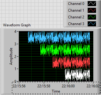
- Generated an array of 100-sample random to represent one second of a waveform.
- Created 4 waveforms on this 100-sample basis. The first waveform (channel 0) is just these 100 points. The second, 1 channel, is the concatenation of string 0 with the base of 100 samples, or a waveform "double". Channel 2 is 1 string concatenated with the base, and channel 3 is 2 string concatenated with the base.
- In order to trace the four channels that they rest 'on' the other, the waveform has the number of the channel added to it. Channel 3 is 3 + (4 copies of the basis of 100 points), a waveform 400-point random centered around a shift of 3.
- All channels have dt value 0.01 (but I guess I could have varied, as well).
- To make the channels start at different times, I started channel N N seconds before channel 0 (by subtracting the index of the loop, I, T0).
- For each channel, I created an attribute called "Chan" equal to "Channel N" (where N = 0, 1, 2 or 3, as the case may be).
This is the plot that results. Scale X is the absolute time value (no Date) using the 24-hour HH: mm
 S format. You can see that the plots are 1, 2, 3 and 4 seconds of time, and are offset from each other by a second. I used the trace attributes to change the name to the respective attribute.
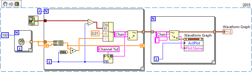
The code to do this is very simple - I almost don't need to show it, because I think it is completely described by the text above, but this is here:
Now, it was not that much faster that some of your previous posts, when you refused to your postcode, "guess us" what you wanted (but not to not correctly guess), you tried to "push" us in the right direction (still refuses to post code), and no one seemed very happy?
Bob Schor
-
Hello
I want to generate the continuous signal and at the same time I want to read that signal that I generate using a single card DAQ. I want to generate signal and the received signal is synchronized and in phase.
I looked at several samples on the sync, but it quiet confusing. One using the same clock of entry while the other use a trigger to start. I use the PCI-6024E DAQ card.
Can someone help me in this regard?
In two of these screenshots, the task to HAVE started first (that's what you want, because it is the task of the slave).
Typically for AO, you can simply write a unique period of your waveform, and then regenerate again and again. Your waveform would be preset before the task starts. If you need to update the waveform on the fly according to enter programming during execution of the task, you would disable the regeneration. In addition, if the wave form is such that it cannot be easily represented by a predefined buffer (for example, it is a strange frequency which is not a same ditch at the bottom of the sample clock), then non-regeneration is the way to go.
Best regards
-
DAQmx how to control the level of tension AO paused for a relaxing break?
I have an application where I need to generate a waveform of a fixed frequency (~ 200 kHz) and the amplitude, but for differing them burst lengths and different lengths of time between bursts. These bursts and these delays are controlled by a line of DIO to generate the relaxing break. I also need to have the output voltage analog voltage controlled between bursts of waveform. I explored using various trigger options, the break seems to be the best solution, but I'm difficult to control the particular point of the end of the waveform during the break occurs to make sure that the break is at the same specific voltage when the wave is hidden. I try to adjust the position of the example 'Analog output Pause for the periodic Signal with regeneration on specimen' but cannot get regular tension during the break I'm after. I use a card Series DAQ. X is there a simple way to pre-set the tension that will be broadcast during the paused state when using a relaxing break? I was not able to find it in the examples or documents. I can't use the code of reference AO set example because it is a software-driven and does not fit into the model of schedule I need to generate.
Hello
I don't think there is a way to establish a certain level on the analog output, based on a relaxing break. I watch using a redeclenchables task analog output and do every hour of beginning to the required voltage.
Maybe you are looking for
-
Qosmio G35 - TV tuner does not work in Turkey
I bought G35-AV650 of us (ntsc) and it does not wotk in turkey (pal)is it possible to change NTSC to palThanks in advance CEM
-
Why does a lock appear on my screen?
His lock of color one blue. Sometimes, it appears locked and sometimes not. I can't understand why its there and how to get rid of. It is very annoying. Please can someone help?
-
Pavilion 15-e097sa: maximum capacity of hard drive on hp Pavilion 15-e097sa
Hi guys, can someone tell me what is the maximum capacity of hard drive for my laptop (Pavilion 15-e097sa), I wan't upgrade to a 2 TB drive.
-
Looking for the USB Ports on the front of my desk for my ipod
my model is HP P7-1044, Windows 7 I'm looking at the front of my pc from one place with easy access to recharging my ipod. so my question is can plug you all devices that need a USB Port in the back of my pc. only. I do not understand this sd/mmc, xd
-
.jpg image of .dll to convert icon
How can I change an image file (.jpg) in a (.dll) desktop icon? Windows 7