exact time between digital power
Hi all
I had posted this before the Council of software, but I think that this forum is more appropriate. I'm operating a valve that uses a digital signal (0 or 1) to turn on and off. I need to change the time it remains open from 5ms to 100 m, I was using "wait until ms" block so far, but it is not very accurate.
I enclose the final version of the program that I use currently. The
the DAQ card is pci 6516. We also have a card PCI-6251, which if I understand correctly, can be used
for material of timing, but I'm not really sure, how to on this subject. I have
would be grateful if someone could push me in the right direction.
Concerning
Abhishek
Hi Jordan
I got the program working. However I have two questions and he wopuld be awesome if you could respond to them.
1. can I connect the 6251 (68 pin device) to a connector block CB-37F-LP (37-pin accessory screw terminals).
2. can I I out a single start/stop command (I want to spend the valve only once), instead of a pulse based on the frequency in the program.
Concerning
Abhishek
Tags: NI Hardware
Similar Questions
-
How can I measure the time between each two successive increase edges, using digital input?
Hello
I have tried two measure the time in seconds between each two successive rising edges on a digital input.
So far I managed to detect the rising edge, increment a counter at each rising edge and take the time during which the increase is edge
all I need now is subtract edge currently rising from the previous era of edge rising to calculate (T), which can be 1/frequency and display in real time for the user.
but I do not know how to do this

Can someone help me please!
Woah!

Sorry Apok, but your code becomes much too complicated and salty. I don't think that all records to offset or Boolean conversion/operators are necessary at all.
If you want to measure the time between two keys so it's another (much less complicated) way. It simply records the time when press button in a registry change, then compares the two.
-
Measure the time between two digital pulse
Hello
For a non-critical calendar application, I need to measure the time interval between consecutive TTL pulses, ranging from the order of 0.5 s for a few seconds, with a low accuracy of +/-10-50ms. The interval being measured varies between the rising edge of the first pulse and the front of the next and so on.
I have several input lines I need to deal with. Because it's a critical machination low cost, I don't want to use digital counters for each line, so I work with an acquisition of data USB6008 and have connected the input rows TTL on the digital inputs of the device. Avoiding will be sufficient.
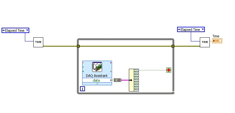
I found a good example of VI on discussion forums that does almost the same thing, only it uses instead of the DAQ Assistant user input. The VI works including the time the program going on in a while loop. I replaced with the DAQ Assistant output (a channel) user input in the hope that it is still work.
When I run the program in "run once" mode, it seems to work perfectly. However, in "continuous run" it measures only a very small interval, probably just the time between two samples. I think it has something to do with the help of a while loop in combination with the DAQ Assistant. Anyone who has any suggestions how to solve this problem?
Thank you!
OK... first of all, you should never use the button "run continuously. I wish that NEITHER would be to eliminate it, but told me that it is sometimes useful for debugging. If you want your program to run over and over again, use a while loop with a stop"" button.
If I'm reading your code correctly, you make your initial moment, and then collect data from data acquisition. When one of the channels is "T", you stop your loop and the end time of capture. (By the way, why you convert your table to a cluster? Why not just index the appropriate channel in the table directly?)
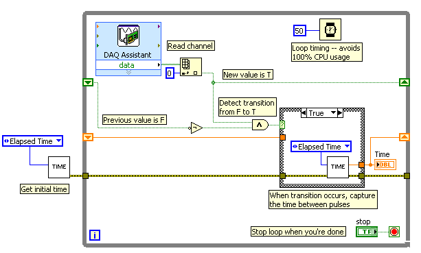
Since you want to capture the time between two consecutive pulses, you need to know when a transition has occurred... i. e when your digital line went from F (no pulse) to T (pulse start). This will give you your forehead. Right now, all you're doing is looking for a value T - so you have no way of knowing if you are looking for to the previous impulse again, or a new impetus. You also burn 100% of your processor with the way you have your programme in place.
You need a small loop delay so that your VI is not 100% of your hogs CPU time. Given that you can live with an accuracy of 50msec, what I suggest that you use.
See attached picture for you give an idea of how to implement. He will probably need some refining operations, but it should point you in the right direction.
I hope this helps.
-
How can I get the digital power meter?
How can I get the digital power meter?
I use a method similar to the example below to measure the market factor using the inputs of a multifunction data acquisition meter. If the duty cycle is 0% or 100% for a given period, DAQ reading times out and returns an error. In this case, I would get the digital state of the counter of entry so I can put as cycle to 0% or 100%. I want to do it without knowing the digital port and line the entrance of counter... for example I would like to continue referencing DAQ/ctrX since I already have this information.
The application uses an M series: PXI-6229 DAQ and LabVIEW 2011 to make a system customized for VeriStand.
https://decibel.NI.com/content/docs/doc-12396
For the moment I wired the block diagram to add a case structure to check the meter ID and string constants to set the identifier of digital input, as they share the physical connection. As much as I can say that makes the specific code for the PXI-6229 (or any DAQ with only two counters that share connections with p2.1 and p) 1.4
I have attached the VI sub.
When the device is used with a different data acquisition, I can add the connection and/or separate control. Looks like at least one will be necessary given that the meter can only detect the edges... I think it was the piece of information I needed.
Thanks for your help!
-
How to find the time between two channels of entry in the data acquisition card or pci 6036
Hello
I read a lot-related posts on the simultaneous measurement of two input voltage of similar channels in map data acquisition. I know that the best material is "simultaneous measurments of the Series DAQ cards" but I only pci data acquisition card 6036 and I try to understand what is the time between the reading of the two channels . This period is always constant? (must it rely on a voltage (amplitude, frequency, waveform..). I send the sine wave (s) to the two channels and read the values of V, if they read the same value, the difference should always be zero but I get-0,002 to 0.002 Volt difference (I must find a way to convert it in time). A screenshot of my VI is attached. I wonder how I can accurately measure the time delay between the channel.
I am open to any suggestion, my final goal to read exactly two channels at the same time ((ou connaître le délai exact donc je peux correspondre les données correspondantes étant donné le temps de retard))
Hi spinup,
better you should post your question in the forum of LabVIEW, LabWindows/CVI is used

Good luck.
-
Computer clock loses time between stop market.
A response was that I could use a change of battery, but I got this Dell computer for a year. Is it possible to change the battery already?
If he loses time between when you turn off and on again, it's a sign that maybe it's that the CMOS battery has failed.
Battery size piece, trickle of power is to keep system settings when the computer is turned off.They cost about $5 to buy.
http://www.computerhope.com/issues/ch000239.htm
http://technofriends.in/2008/05/03/how-to-change-your-CMOS-battery-and-re-energise-your-BIOS/
How to replace a facility above links.
Contact Dell 1 as appropriate just in a secured claim: http://support.dell.com/
Mick Murphy - Microsoft partner
-
I use VISA in communication series with PIC18F4550 (mcu, USB copy series), I found if I read immdiately afte writing, I can't get the right data all the time. It seems that the time should be at the same time between write and read funciton, and delay must be greater than 0.35 sec.
Fact delay is necessary or I used to misuse Scripture VISA and playback function?
Also look at the use of the chariot of termination and the setting of time-out to your advantage.
1 turn on the tank of termination (depends on YOUR DEVICE PIC18F4550, read the instructions)
2 set the timeout to something MUCH longer than necessary. (like 1000 ms)
Write then followed the reading. No delay, bytes read no. to the port
For the bytes of lonely bytes expected reading feature request.
The Read function will wait for the full message that ends with the chariot of termination and will return with your message as soon as he gets the chariot of the termination. Or will he wait until the timeout before giving up on your device.
You can then decide what to do with if time-out error message never comes.
I have devices that take more than 3 seconds to answer because they have to go do something before they can meet. Some of my exhalations runs to as high as 10 sec. I have set the timeout on the fly, based on the order that I send.
-
Measure the time between the ridges of the periodic input signal
We have built a circuit which is supposed to mimic an Exercycle. We have an IR switch and a spinning wheel, the rccb meets a comparator circuit and the output of the element of comparison, we have running in LabView. We successfully were able to measure the number of rotations of the wheel and the total distance travelled by the wheel, but are struggling to measure speed. We cannot find a way to measure the time between picks in real time, which we could then divide the wheel circumference and calculate the speed in real time. The VI I posted has a square wave simulated rather than the signal we receive on our circuit. Thanks in advance for the help.
Jon and David
I think you're overloading the things trying to get the time between two pulses. Instead, you can use the VI Express your measures and select frequency for her custom. Then, you can multiply the circumference of the wheel of the frequency to get the speed.
I hope this helps.
-Christina
-
Let a burn of LED on a random time between 3 and 7 seconds
Hi all
Probably, it's a matter of simpel for many of you, but not for me. I try to make a counter reaction time. And I hope someone can help me with the first part: the led must Flash on a random time between 3 and 7 seconds.
After this need to measure the time between burning directed and by pressing the stop button
Results ranking in a table
After the display of ten measures of response time average.
I hope someone can help me to launch it, I need it for school.
Thank you!
Matthijs
Netherlands
Code Simon put tapped off. The Down button was a nice touch, but cannot be disabled so we were testing times preaction and the param 'Trial' could get pretty messy especially on a series of rehearsal
-
Hey guys, Hello.
I need to calculate the time between 2 summits and it does not work very well.Can you help me?!
I'm using NI USB-9221, with 2 channels.
I need to calculate the time between peak (12 volts) of channel 1 and channel 2.
Here's my attached .vi.
Thank you very much for the help.
This is!
-
Take the time between two values
Hi people,
I have a problem and I know idea how to solve... I need help.
The problem is I want to take the time between two values max as you can see in the chart.
For example, in the image that I have add
4.5 - 1 840 = 2.66
And enter this value in the 'time between mostra '.
It's that I want...
But what I think is very complicated, because I don't know how to take the time correctly and does remove...
Thank you very much
Any solution?
Hi jocuma,
I tried something and hope that helps u.
Just create two arrays of temperature and voltage. First of all, I'll get the value of the voltage when it is more of a certain value and that same index to get the value of time and store in the shift register.
When I get the second higher than the limit value, I'll get time and subtract the previous value.
-
the BACKSPACE key does not work properly and when I want to type a leter twice I have white some time between them
Hello
In what program?
Don
-
Nor-Daq 6251 set hour/time between samples
I'm trying to calculate the expected error for an experience that I do and I don't know if I've done enough to determine the 'break-in' or the time between samples.
We use 8 differential channels to the maximum sampling frequency, the card can do (1.25. MECH / s). If I understand correctly, the minimum time between each sample must be 1 / 1.25 M, or 800 nanoseconds, such as the maximum time between sampling channel 1 and channel 16 would order 12uS (800nS * 15). If the expected voltage settings are the same for each channel (+/-10v), would a break-in? If so, how long?
In addition, if a channel is upward, and its tensions have an offset, DC on 5 or 6 volts, should that severely increase break-in if all other channels averaged about +/-1v?
I'm sorry for the basic question, I couldn't find a straight answer in the documentation.
Hi LSUgrad85,
When looking for specific device information detailed Specifications for this device will usually provide the details you are looking for. After the back if you have questions about the information in the detailed specifications.
I hope this helps!
Kind regards
-
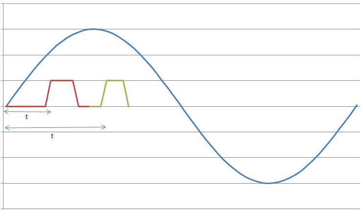
I have a sine wave of 50 Hz and a pulse of the signal on the same chart. The difference in phase between the two is between 0-90 degrees.
Now I need to calculate the time difference between (when the sinusoidal wave passes through zero volts) and (when the pulse increases). The frequency will remain about even for the two signals.
The request is for a three-phase generator. In simple terms, when the difference in time between the passage to zero of the sine wave and pulse increases increases, it means that the load on the generator has increased.
I am a novice user of LabView (version 9, 2009), maybe it's a very simple problem but I was pulling on my hair for the past few days and couldn't understand anything. Any help would be greatly appreciated. I use DAQ USB-6008 to measure these tensions and the impulse of the generator and a sensor
I have attached a jpg file (a graphic that I just did with excel to explain). The time 't' is what I'm trying to measure
See you soon
Zdzislaw
Awais.h,
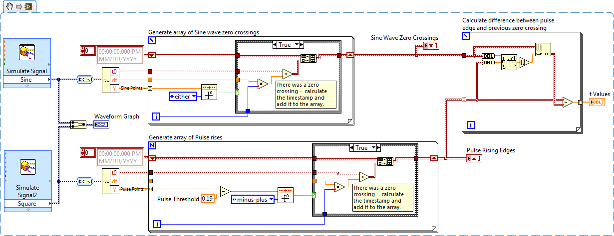
For problems of this kind I recommend start writing the granular steps you would take to manually fix this problem. You can't say LabVIEW (or any programming language) If you can't succinctly describe the solution to your problem.
The I want to address this problem is to:
- find all the zero crossing points and edges on the rise
- for every rising edge find the difference between the timestamp and previous passage by zero
Here is an implementation of this algorithm LabVIEW:
-
How to set the time between workstations and Server 2008 R2
Hello world
I have problem with my Server 2008 R2
all the workstations on my company doesn't synchronize the time on the domain controller
I tried many ways to set up automatic synchronization via command prompt (Net time) and its does not work
Please help me configure the time between the DC and the workstations
Thank you
Windows Server forums:
http://social.technet.Microsoft.com/forums/en-us/category/WindowsServer/
Maybe you are looking for
-
Why do I need to connect to IEEE xplore?
I use a computer at my University. Sometimes I need to search for articles in IEEE Xplore http://ieeexplore.ieee.org/Xplore/home.jsp Actually, since there is a computer in my University, I don't need no connection IEEE Xplore to get the document I wa
-
Satellite A200 PSAF3A does not start with 4 GB
Hello I have a model A200 PSAF3A-0QH01N.I've been led to believe that it supports 4 GB of RAM but does not start with 4 GB, freezes at the toshiba logo.Also have A100 running new 4 GB RAM works very well in this machine. Have updated BIOS did not hel
-
Intel Xeon E5-2689 compatibility with C30
Hello The Intel Xeon E5-2689 is compatible with the workstation C30 ? I couldn't find any reference to this CPU on the Lenovo Web site and it is also not mentioned in the ThinkStation (Sep 2013 ed) personal systems reference. Thank you!
-
The Windows update installation error.
I'm trying to update my windows XP with the next update and it is always in the back. (The update could not be installed) Initializing installation... done! Installation of Microsoft .NET Framework 3.5 Service Pack 1 and the .NET Framework 3.5 Family
-
Cannot access my router through the Explorer configuration page
I need to do a port forwarding on my router. My internet connection works (even if she falls occasionally) and I can also connect to other computers on my network. However, I cannot access my router through IE page (I get a message saying: page not f