Export of components of multisim to ultiboard
I would like to export my conception of multisim to ultiboard. I have several pages in my multisim schematic and I when I export to ultiboard, I would like to components in a page to be placed next to each other in ultiboard. What should I do?
Hello
When you transfer a Multisim with Ultiboard multipage drawing, all the parts are transferred at the same time and placed outside the Board outline and there is no way automatically group parts that come from a specific page.
Now, one thing you could do is to create a Group of party in Multisim. Open a page and select all components, then switch to the display of the worksheet, components tab. Go to the part of group column, click a cell and type a name for the group. Repeat for other pages if necessary.
Transfer from design to Ultiboard. Now, let's say you want to place on the Board describe only parts of a specific page. In worksheet view , click on the parts tab. In the Group column, select the whole group; Only the components that belong to this group will be highlighted. Now you can just drag / drop all the components.
I hope this helps.
Tags: NI Software
Similar Questions
-
Missing components in my file Ultiboard if I transfer my file Multisim
Hello!
I am after this Introduction:
http://www.NI.com/white-paper/10710/en/?CID=Direct_Marketing---em80795&espuid=CNATL000018702741
On the point
5. the part D: transfer to PCB Layout
"" (8) select transfer "transfer to Ultiboard ' transfer to Ultiboard 13.0 and save the netlist file. Ultiboard opens automatically
This pop window ups:
Components with no package will not be exported.
See the results tab in the spreadsheet for a list of these components.Continue with the transfer?
I press ok, and my thread Ultiboard opens.
My resistance do not appear in the file ultiboard.
Any tips?
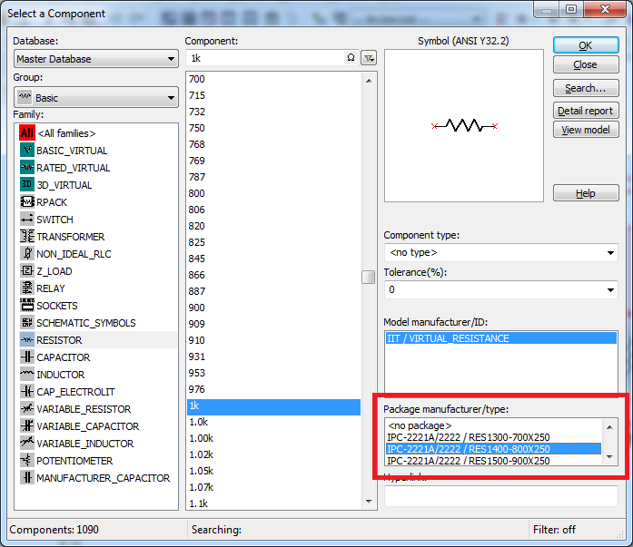
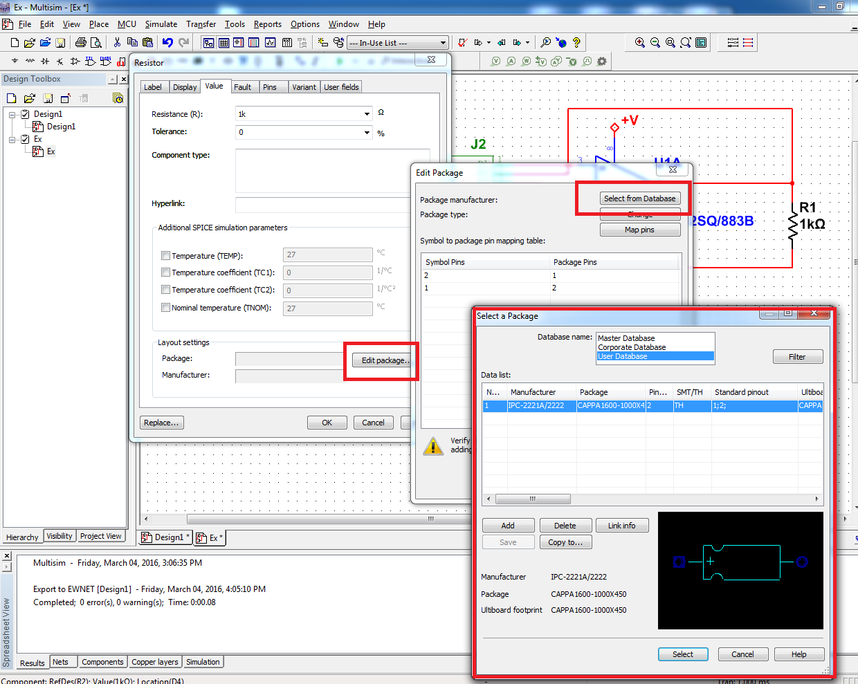
By default, when you place the RLN base, it has no assigned package. The package contains to Ultiboard layout information. Is this the message you saw said you, that the list of components in the spreadsheet was not exported to Ultiboard because they had no information about the package.
If you want to be able to transfer your RLC to Ultiboard components, you can choose a package when placing it down on the diagram:
Or you can add a package to a component that you have already placed. Double-click the component to open its properties and click on the tab 'value '. From there, you can edit the component package and select one in the master's degree, business, or the user database:
Let me know if this helps.
See you soon!
The f
National Instruments
-
Identical components in Multisim
I'm designing a circuit which has several non-ideal identical capacitors (induction) which have a specific C = f (v) [L = f (i)], but I need to change the constants after realization of a simulation. Is there a way to link the components so that I only have 1 component instead of dozens of change? I am trying to eliminate spots I can make mistakes.
Thank you.
I don't know what version of Multisim you use, but from 13.0 you can use parameters of the circuit that can help you with this (View menu > parameters of Circuit)
For help to start with them please see here or here.
I hope this helps,
Jeff
National Instruments
-
I'm missing some components in MultiSim 10.1.1 Verson
I'm doing some homework using MultiSim 10.1.1. When I go to pieces, specifically miss me 74LS283 4-bit binary Adder IC. There is no version that in none of the listed families. How can I to update or updates inport for my database?
I'm not as computer, so please keep things simple in the explanations. I thank anyone and everyone who can help advance.
Hello
You bought a Multisim Student Edition, but your school has the version of education and it is wider and has more features and components. I don't check the edition of students to see if this feature is available, but if it is, you will find it by selecting site > component, go to the "TTL" group and select «74LS» family If you do not see this component in your database, open the attachment, there 74LS283 on the diagram, and you can build your circuit around it.
-
Help! my icons multisim and ultiboard are too small
my icons are too small and I feel that the words are bigger than they should be, nobody knows the reason for this and if so can you please suggest a solution. Thank you. I've attached a picture to show you exactly what I mean.
Hi Samiashi,
By the looks of things, Multisim is just after the settings on the computer. If you go to control panel > display > small 100% (default value), this can help you. This changes the size of your text on your screen.
I hope this helps you,
-
Several weird, sudden problems in Multisim, Ultiboard interface
I have several sudden problems that arose when trying to review a design that changed, I worked on a couple of months ago.
Multisim 10.0.343 strangeness:
1. by clicking on a Multisim, Multisim project file opening, but the project file does not open. By clicking on 'Open' Multisim has the same effect. If I manually open the circuit, the entire project opens as well.
2. I can no longer double click on a component and change the footprint; the button "Replace" is also disabled. I can always change the footpring of spreadsheet view.
3. the icons for the placement of the pieces have changed to blue squares with black patterns (from grey buttons with color schemes).
4. multiple drop-down menus in the top bar disappeared ('reports' is the only one that comes to mind, but the list is significantly smaller).
5 ' transfer' menu has only one option - transfer to Ultiboard 10. There is no rear annotation or annotation.
6. Select 'Transfer to Ultiboard 10' open the splash screen for Ultiboard and gives me the option to choose a file name, but nothing opens after that. There is no blocking or error - just nothing opens.
On a separate note: the last time I did a major revision of this circuit, I changed a lot of net names. NET names, however, has not changed; for example, I renamed a node 'Gsyn' to 'Gs '. The 'Gs' appears in the worksheet view and the properties of the net, but 'Gsyn' always appears on the diagram and is not suppressible.
Ultiboard 10.0.1 strangeness:
1. the renumbering of the components in the design menu translates into a sort of re-assignment pad, causing many connection errors.
2. same mistake earlier in the forums without response: after before annotate Multisim earlier, the list of included changes 'edit the existing component XX' for each component in the design, regardless of whether the component has been modified or not.
3 when you place a trace which is too close to other tracks by my rules of design, I sometimes get advice 'cannot create (1) drop of water ". The program is then suspended until I click on something other than Ultiboard (show Desktop, switch to another program, etc.) When I go back to Ultiboard, the program of the United-grip Nations - but then it works super slowly, no display of updates for a few seconds and zoom in and out in pieces. I have to close and reopen the file to continue working.
Any help would be appreciated - I'm on a deadline, and both programs are more or less completely unusable now.
Hello
Please take a look at the following knowledge base to resolve the issue of Multisim:
It is difficult to tell what is the problem with the annotation to the front without looking at the Multisim and Ultiboard files. If you can, please create a service request to ni.com/ask and send us the files.
1. When you annotate forward, the PIN does not change is the imprint that has changed. If the footprint currently on the design before annotate before is different from the PIN that is in your library, when you transfer annotate, Ultiboard will update the fingerprint with that of your database, this may explain what you see.
2. you need to compare the fingerprint in your schema with what is on the printed circuit, if the fingerprint matches, Ultiboard will get what is on the circuit board to the wide and place a new there. Take a look at the knowledge base of Unplaced Pieces after annotate with impatience , he can explain what you see.
3 turn off the tear drop feature (Options > preferences > PCB design) and carry your board without this feature, once you completed the Board of Directors of routing, add the tear drops (design > add teardrops).
-
Formate Ultiboard Enterprise support export Valor ODB ++?
This question relates to the request of the House of PCB Fab I treat for an export format that works with their new Aegis 'CircuitCam"System. are there characteristics "additional export format" in the Enterprise of Ultiboard version?
Thank you very much, Tod
There is no 'Ultiboard Enterprise' version, so I'm not sure that you are trying to compare the versions, but there is no export ODB ++ to Ultiboard.
See the NI Ultiboard Professional product features for an overview of the professional features.
-
Connections missing in ultiboard when transferred to multisim
I made my design in Multisim, then transferred to Ultiboard. Organized everything how I wanted and make small changes in the schema as needed. All annotated before with no problems until today. All of my lights are not connected although the net are in the files of the Multisim and Ultiboard. Highway runs, but still does not connect...
Very frustrated, if someone could help, that would be appreciated.
I thought about it!
LEDs have a personalized footprint and I got map a symbol to a fingerprint brooch pin not in the database manager. It must be something that shows an error if it does not occur if the user knows where the question is... in any case, it's very good of automatic routing now

-
Import and export application diferent components
Hello guys,.
I work with an application that consists of other small applications to simplify development. The transition from one application to another is transparent to the user.
Some elements, such as auth or point, plugins lists, etc. should be in all applications. The idea is to grow in the main application, and then export the components to the rest of the applications.
To familiarize yourself with the import/export process, you realize that this is not an easy process in some cases. A plugin on request has export and import it on request that b is a seam less process, but to do the same with a page is not equal. If you try this one page, you can export not one application to another without additional, you must edit the sql file and change the ID of the application, the workspace ID if it is another. It's simple.
A more complex case where I've seen is to export lists. I exported a 0 page which is linked to several lists by the action of the export components. With this action we can export components in a precise way. The problem is in the import page and the list in application B, page 0 is created as a new page but not on the lists. What is happening is that lists rocking of app to app B!
I have search in the forum and I found the wwv_flow_id.next_val function that returns a new id for components. Then, can I create a new id and use it without problem? ¿Should I have other considerations? For example:
I don't know if the generated identifier has a special characteristic, or is simply a random number. In this case I could generate a unique id and increases by one of the successive identifications, or is it better to create an ID for each different components?prompt Component Export: LIST 2434019648060868 // old id prompt ...lists -- declare v_list1_new_id number := wwv_flow_id.next_val; //define the new id begin wwv_flow_api.create_list ( p_id=> v_new_id + wwv_flow_api.g_id_offset, p_flow_id=> wwv_flow.g_flow_id, ...); wwv_flow_api.create_list_item ( p_id=> 2434210334060868 + wwv_flow_api.g_id_offset, p_list_id=> v_new_id + wwv_flow_api.g_id_offset, ...); wwv_flow_api.create_list_item ( p_id=> 2434518008060870 + wwv_flow_api.g_id_offset, p_list_id=> v_new_id + wwv_flow_api.g_id_offset, ...); null; end; / //... prompt Component Export: PAGE 0 //... declare s varchar2(32767) := null; l_clob clob; l_length number := 1; begin s := null; wwv_flow_api.create_page_plug ( //... p_plug_source_type=> v_list1_new_id + wwv_flow_api.g_id_offset, p_list_template_id=> 4293149908502306+ wwv_flow_api.g_id_offset, //..); end; /
ConcerningHello
for several components (for example, plugins, the authentications, authorizations), subscription would be my preferred synchronization mechanism. If you use the component of export/import to other parts of the apps, there are also the possibility to use apex_application_install.set_application_id and apex_application_install.set_offset with a fixed offset by application. For example, you install the export of the component of your master repository in demand 100 with offset 100 in app with offset 101 101, etc..
Kind regards
Christian -
Components exported library name?
I have worked on a project and am willing to export my components in a library.
I exported the library and reimported in the project in which I want to use them. However, the names of components I have given in the original have been lost while I find myself with names of components such as CustomComponent3_2, Button2_1, and Text3 (instead of ConversionsGroup, AcceptButton and StatusText).
Is there a way to keep the names of these components in a library export and import?
Hello
I think there are two things:
(1) it seems that maybe you had renamed the components in the layers panel, but not in the library panel. The layers panel lets you put a name on each instance. When you export your library, you export the definitions, which have their own names. We are working on this distinction more clear.
(2) If you re - import items into the same project, catalyst will add numbers to give them unique names (the names of components must be unique).
-Adam
-
Change of fuse in Multisim print?
Hello guys,.
I met a problem when using the Multisim and Ultiboard (Version 10.1), I use a fuse in the circuit, but the footprint is not editable, when you do one annotation in front of ultiboard, I still need to change the footprint of the fuse. Does anyone have a solution to this issue?
Thank you
Toni
Hi Toni,
Have you tried to change the footprint in the worksheet view? Try to do this:
- Make sure that the worksheet view is visible in Multisim. Click view > view worksheet. By default, the spreadsheet view is down Multisim.
- Click the components tab of the spreadsheet view
- Click the tab of the footprint of the fuse to change
- Change the print window should appear and you should be able to change your footprint
If this does not work, could you upload your design Multisim for us to take a look at?
Hope that helps.
-
How can I remove an existing model components?
I have an old drawing is updated. Several items have been removed from the schematic in Multisim, and changes have been annotated with impatience to Ultiboard.
The components were still available to Ultiboard PCB (all other programs I've used automatically deleted).
I manually deleted the components in Ultiboard. Now the DRC Ultiboard is telling me that the components are not in the design. No joke!
I see that these components are listed in the netlist in Ultiboard, even if they have been removed from the netlist in Multisim.
Apparently, Multisim fails to transmit new information to netlist to Ultiboard with before annotation - what is quite poor, because it is the object of an annotation before transmitting the design changes!
How send netlist update of Multisim with Ultiboard?
PRH
V11.0
Hi PRH.
The component should be removed, but try this:
In Ultiboard, select Tools > Netlist Editor, click the Remove button, and then select all your nets and delete them. Components and traces should remain. Now try before annotation of Multisim.
If this does not work, I like to look at your file. If you can send me a private message with your email address and I will contact you.
-
Nets not transferred to Ultiboard
I have a Multisim 13 design for an extension table simple using a card-edge connector. The custom component is the Multisim and Ultiboard of databases. The nets appear in Multisim, but the ewnet file does not show their links with the custom component and so (I guess) just Ultiboard ignores all.
What should I do to get this to transfer the nets through?
I tried to reach one of the ewnet files, but that failed.
Thank you
Dave
DOH! Forgot card footprint component pins.
Now works as expected.
Dave
-
Is it possible to export a DXF file Multisim schematics? Our standard procedure is to export the drawings to DXF so various borders of the company and the signature boxes can be added. We use OrCAD before today to make patterns and with that, we are able to export DXF.
If this is are not possible with the current version of Multisim there plans to add this feature in the future?
Thank you
Robert
Power of Multisim Pro edition
10.1.1
rmoss78,
There is no native ability, but you can do this by using a few pieces of software that are relatively cheap.
1. you will need a PDF print driver. Some newer PCs today come with this standard. If not, I recommended it in the past (www.pdf995.com).
2. you will need a PDF to DXF conversion tool. I recommend this one (www.aidecad.com) and have heard customers have a success with her.
Note - There are probably other free or cheap - conversion tools if you have a good luck with others, please post it here...
Now, all you have to do is print the diagram as PDF (nice to have it in PDF format anyway) and then use the PDF to DXF conversion tool to get it into a drawing in Autocad or similar Assembly tool for writing mechanics.
The downside is now that the DXF resulting will be lines and not any organized 'blocks' that you can reuse in Autocad...
Kind regards
Pat Noonan
-
Hello
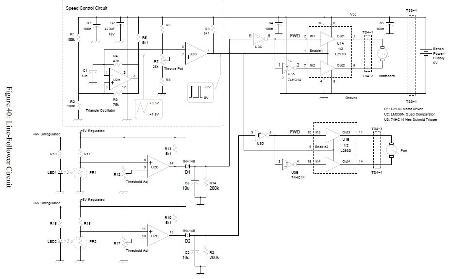
I'm new in the world of Multisim. Just bought the product and hoped that it would allow to draw me circuit diagrams for the robot I design.
Basis components L293D, LM324 and 74HC14.
I intend to adapt the circuit diagrams of: http://www.syscompdesign.com/mechbot/mechbot-lab-manual.pdf to my needs.
The diagram should be similar to the one below.
Unfortunately I can't find the components in MultiSim components library. Do I need another product or can this be achieved using multisim?
Can someone help me find a solution?
Voila, I thought you wanted the L293 which is a totally different part.
Maybe you are looking for
-
Via mijn web brouwzer mozilla firefox kom ik op intranet werkgeverEnglish om 00:00 iets wordt finished you question zou iets als Français like send later plug-ins Jan
-
I'm about to the partition of my hard drive and I want to know if I would be able to partition my hard drive, then if I need is no longer the partition (I install Windows without Boot Camp), it will take format me the entire drive or I'll be able to
-
legal aspects on reinstalling xp on several laptops to renovate and sell
I have a friend who is planning to buy laptop computers if the Government used, hard disks are cleaned and he asked me about the installation of xp pro on them. I don't know if the license key is always on them or is still legible. I need to know wh
-
Need driver ethernet acer laptop
How can I get an erthernet driver?
-
(Redirected) Vostro Wifi card, 2520
My wireless adapter seems to have broken. I can only connect to wireless internet when my laptop is placed right next to the router and I ran to my wireless connection Dell diagnostics indicated that I need a hardware replacement. It's all good and