Identical components in Multisim
I'm designing a circuit which has several non-ideal identical capacitors (induction) which have a specific C = f (v) [L = f (i)], but I need to change the constants after realization of a simulation. Is there a way to link the components so that I only have 1 component instead of dozens of change? I am trying to eliminate spots I can make mistakes.
Thank you.
I don't know what version of Multisim you use, but from 13.0 you can use parameters of the circuit that can help you with this (View menu > parameters of Circuit)
For help to start with them please see here or here.
I hope this helps,
Jeff
National Instruments
Tags: NI Software
Similar Questions
-
Export of components of multisim to ultiboard
I would like to export my conception of multisim to ultiboard. I have several pages in my multisim schematic and I when I export to ultiboard, I would like to components in a page to be placed next to each other in ultiboard. What should I do?
Hello
When you transfer a Multisim with Ultiboard multipage drawing, all the parts are transferred at the same time and placed outside the Board outline and there is no way automatically group parts that come from a specific page.
Now, one thing you could do is to create a Group of party in Multisim. Open a page and select all components, then switch to the display of the worksheet, components tab. Go to the part of group column, click a cell and type a name for the group. Repeat for other pages if necessary.
Transfer from design to Ultiboard. Now, let's say you want to place on the Board describe only parts of a specific page. In worksheet view , click on the parts tab. In the Group column, select the whole group; Only the components that belong to this group will be highlighted. Now you can just drag / drop all the components.
I hope this helps.
-
I'm missing some components in MultiSim 10.1.1 Verson
I'm doing some homework using MultiSim 10.1.1. When I go to pieces, specifically miss me 74LS283 4-bit binary Adder IC. There is no version that in none of the listed families. How can I to update or updates inport for my database?
I'm not as computer, so please keep things simple in the explanations. I thank anyone and everyone who can help advance.
Hello
You bought a Multisim Student Edition, but your school has the version of education and it is wider and has more features and components. I don't check the edition of students to see if this feature is available, but if it is, you will find it by selecting site > component, go to the "TTL" group and select «74LS» family If you do not see this component in your database, open the attachment, there 74LS283 on the diagram, and you can build your circuit around it.
-
Hello
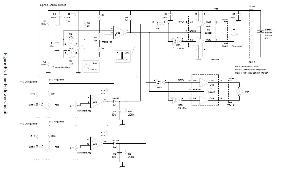
I'm new in the world of Multisim. Just bought the product and hoped that it would allow to draw me circuit diagrams for the robot I design.
Basis components L293D, LM324 and 74HC14.
I intend to adapt the circuit diagrams of: http://www.syscompdesign.com/mechbot/mechbot-lab-manual.pdf to my needs.
The diagram should be similar to the one below.
Unfortunately I can't find the components in MultiSim components library. Do I need another product or can this be achieved using multisim?
Can someone help me find a solution?
Voila, I thought you wanted the L293 which is a totally different part.
-
Hello
I was looking to create custom components, but I can't find anything for me.
I would like to make a custom led template or a custom template of probe to check low and high in a logic circuit.
Problem is, existing probe is HUGE and I would like to do something a lot smaller.
Y at - it a tutorial, how to make these 'animated' components?
Thank you very much

Hello
All of the "interactive" components in Multisim are coded in hard and unforatunately, you will not be able to create your own symbol that will turn during the simulation.
-
Hello!
I try to connect to microchip DAC7642-43, collected the regime created by the statement but why on an output of the plan is do not present a signal.
Command prompt I am doing wrong?Data sheet: http://lkharlamov.chelcom.ru/sites/default/files/DAC7642-43.pdf
Hello
It seems that the component you chose isn't simulatable. Many components in Multisim can be used in the simulation, but many cannot. There is a lot of work to create models of simulation for components and it is impossible to make all components operate in the simulation. Those who cannot be simulated appear in green when you place it on your schema, and those who can be simulated see the place in black (but sometimes as well). Another way to know whether or not a component is simulatable is looking FAB/ID model area when you place a component. If the box is empty or that it has an article that says "GENERIC/EMPTY", then it is not simulatable. If it contains one or more items in the box, then the component will work in simulation.
As an alternative to your problem, you can try the VDAC16 of the family of the ADC_DAC component. This component is a virtual component which does not exist in real life, but can perform simulations on it.
Hope that helps.
-
Creation of evil silicone diode
Hello
I am creating this circuit in multisim, http://www.aaroncake.net/circuits/phonebug.asp?showcomments=all
The problem is that multisim n do not have a resistance of silicone 1SS119.
I thought I would modify an existing one to create the 1ss119 yourself using values in a data sheet that I found http://html.alldatasheet.com/html-pdf/246433/RENESAS/1SS119/592/2/1SS119.html but I can not because when I click on 'Edition model' on for any diode, none of the variables are the same as the data sheet.
I tried to create some custom components in multisim, but I'm still stuck.
Hello
You must follow the instructions in the link below:
https://decibel.NI.com/content/groups/circuit/blog/2011/04/06/component-creation-101
When you get to step 5, click the designer and choose to create a model of the diode. This is where you will be able to enter the values of the data sheet.
I hope this helps.
-
Loss of Focus in a custom component ItemRendered
I have a custom component which is composed of multiple TextAreas and displayed on the screen with other identical components via itemRenderer where = 'true' useVirtualLayout.
After I clicked on an text box to give it focus, I want to be able to tab to the next TextArea. But instead of emphasis here, the emphasis is the parent of the itemRenderer, forces me to click in the text box in my component to give it focus.
I tried to use focusManager.setFocus (parm) - corresponding parm to the id text box , I want to take focus, but if I did that with focusManager.getFocus (), I find that the parent currently has the focus.
I tried also provide each TextArea with a tabIndex (instead of using focusManager.setFocus). But it seems to be ignored.
Any ideas?
You need to maybe get the keyFocusChange event and cancel it.
-
How do you get listData to a DataGrid itemRenderer?
I want to do simple reusable components in .mxml use in my dataGrid classes. I don't want to specify the data field because I could use the same rendering engine of several columns in the same grid (for example a converter box) and I don't want to make several identical components whose only difference is the value that they draw 'data. To do this, I need to access "listData. Specifically listData.dataField. According to the docs, I need to implement the mx.controls.listClasses.IDropInListRenderer. I tried the following in my mxml code:
< mx:Component id = "reusableEditor" >
< mx:HBox implements = "mx.controls.dataGridClasses.DataGridItemRenderer" >
import mx.controls.dataGridClasses
.. content and display logic data [listData.dataField]...
< / mx:HBox >
< / mx:Component >
"I get an unnecessary error in Flex Builder, saying that"an internal build error has occurred"and only guess now that it is the 'implements ="mx.controls.dataGridClasses.DataGridItemRenderer' line ' (when I delete this line, things work very well). I have not found anywhere to check if I implement this correctly because there is not an example of work that does what I want to do - even if I use DataGrid 100's of times more often than any other list class! The example of TreeRenderer later in the docs is the only code addressing this issue, but it is a class AS that does not (as far as I can tell) a container such as HBox and doesn't implement any interface.
Just how can the question, I have access to listData?the
I finally understood what the ambiguous compiler error means... I had not implemented the functions required for the interface. Here is the working code that is declared as a component internal or external .mxml file displays the value of the column without explicitly defining what is this value.Although this component is very simple, it was very difficult to understand how to implement documentation... I hope someone from Adobe takes note.
[Bindable]
public var dp:Array = [{num:2, bool:true}, {num:3, bool:false}];
]]>
Import mx.controls.listClasses.BaseListData;
Import mx.controls.dataGridClasses.DataGridListData;private var _listData:DataGridListData;
[Bindable ("dataChange")]
public function get listData (): {BaseListData}
Return _listData;
}public function set {listData(value:BaseListData):void}
_listData = DataGridListData (value);
}override public function drawFocus(focused:Boolean):void {}
check.setFocus ();
}override protected function updateDisplayList(unscaledWidth:Number,_unscaledHeight:Number):void {}
super.updateDisplayList (unscaledWidth, unscaledHeight);
If {(super.data)
var dgListData:DataGridListData = DataGridListData (listData);
for some reason, setting check.selected here translates into behaviour bug
Check.Selected = data [dgListData.dataField];
}
}define a getter based on the "dataChange" event seems to update the value of the checkbox correctly when
clicked, decreed, sorting, etc...
In addition, doing it this way avoids those annoying "data binding will not be able to detect changes... blah blah"
[Bindable ("dataChange")]
public function get val (): Boolean {}
Return Boolean (data [_listData.dataField]);
}]]>
If anyone has any suggestions or comments, please let me know... I'm still trying to figure the best way to do it.
-
For a long time I use Multisim 10.1 in the simulation of circuits, but now I
truble to place the components in the schema: order Place/components
appears disability (the characters are blacked out) and I don't understand why.
Is there an action to perform to restore function?
(I already rebooted the Multisim disc, but nothing changes!)
Problem solved!
Thank you very much.
nonnog
-
Components of identity management
Hello
We plan to go with the Installation of the identity management which is part of the Fusion Applications. So I would like to know what are the elements that arise as part of Installation of identity management and what would be the material condition for the Installation of identity management.
Kind regards
CVSee certification matrix for hardware and all kinds of requirement:
http://www.Oracle.com/technetwork/middleware/ID-Mgmt/identity-accessmgmt-11gr2certmatrix-1714221.xlsThis is for Oracle identity management. Its main components are:
-Oracle database
-Java 1.6
-Weblogic server
-Oracle Identity Manager
-Server SOA
-Repository creation utilityKind regards
GP -
Missing components in my file Ultiboard if I transfer my file Multisim
Hello!
I am after this Introduction:
http://www.NI.com/white-paper/10710/en/?CID=Direct_Marketing---em80795&espuid=CNATL000018702741
On the point
5. the part D: transfer to PCB Layout
"" (8) select transfer "transfer to Ultiboard ' transfer to Ultiboard 13.0 and save the netlist file. Ultiboard opens automatically
This pop window ups:
Components with no package will not be exported.
See the results tab in the spreadsheet for a list of these components.Continue with the transfer?
I press ok, and my thread Ultiboard opens.
My resistance do not appear in the file ultiboard.
Any tips?
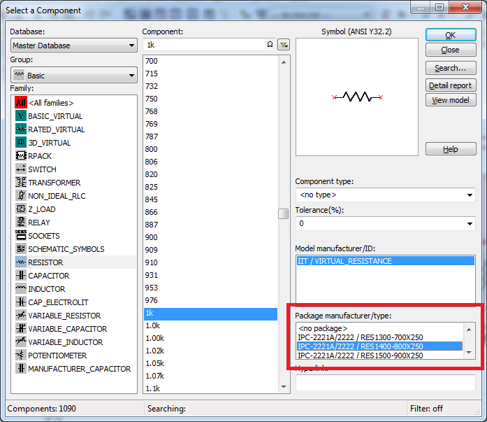
By default, when you place the RLN base, it has no assigned package. The package contains to Ultiboard layout information. Is this the message you saw said you, that the list of components in the spreadsheet was not exported to Ultiboard because they had no information about the package.
If you want to be able to transfer your RLC to Ultiboard components, you can choose a package when placing it down on the diagram:
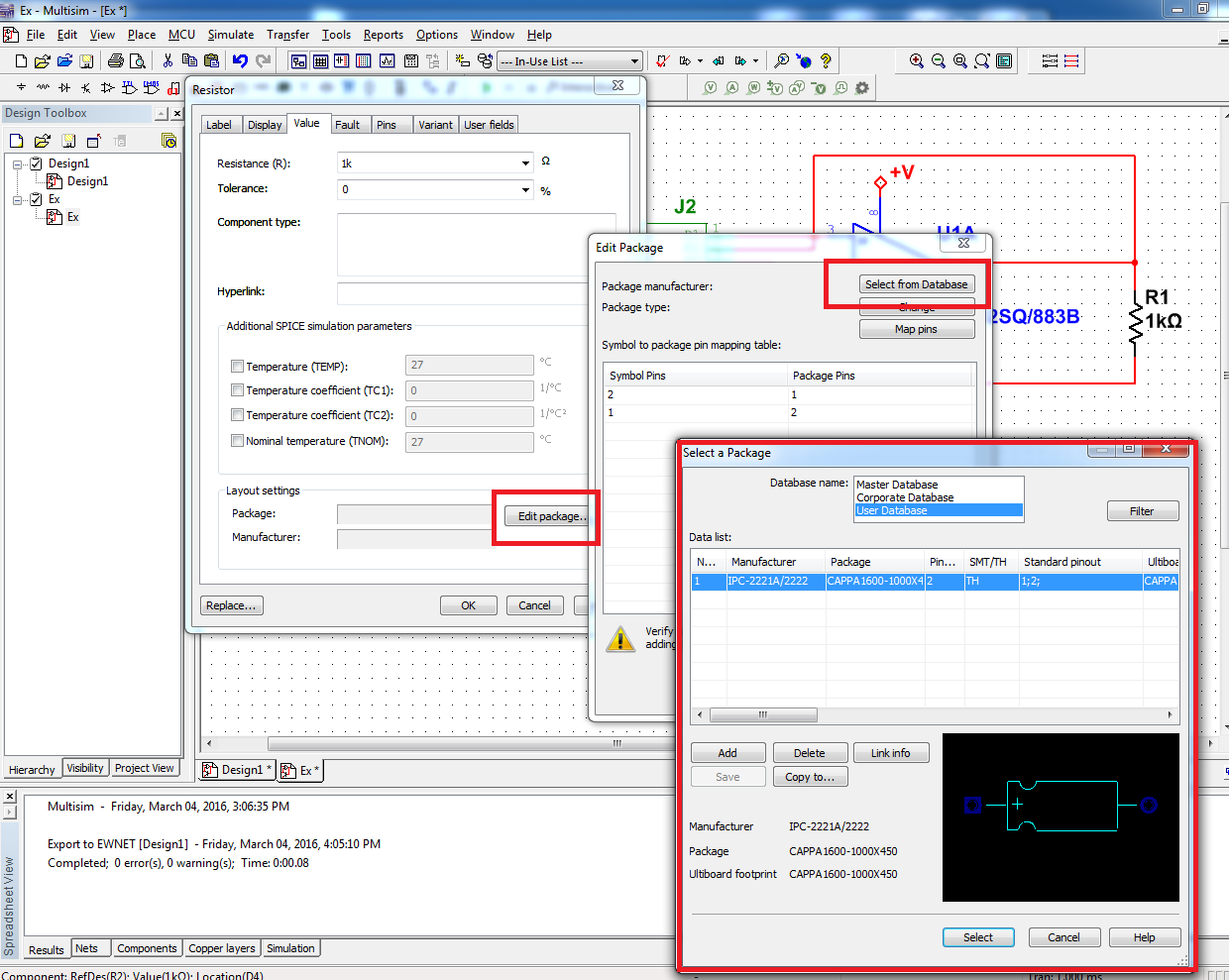
Or you can add a package to a component that you have already placed. Double-click the component to open its properties and click on the tab 'value '. From there, you can edit the component package and select one in the master's degree, business, or the user database:
Let me know if this helps.
See you soon!
The f
National Instruments
-
Multisim - location database components list
Is there a way to include in the Schema pane lists the exact location (or at least, including databases) components come? The column of the family does not help if the same family exist in users and internal databases. My company has a policy to use only components of the database in a new design. I want to check some drawings completed and make sure that it is not all the components of a user database. The only way I can do now is to check the properties of each component, because the exact location is listed in the values tab.
Any help would be GREATLY appreciated. I have a few hundred components on the schematic, and it'll take a lot of time if I have to check them one at a time. Thank you.
Michael
Hello m22oswald,
In addition, you can go to tools > update components. This should get you a list of components with properties, which of them is the database.
I don't see a way to export the information, but at least you'll be able to see the list.
Kind regards
Luis C.
-
Unable to connect the path between two components. Blue MultiSIM.
Hello
With the help of Multisim blue.
On the use of ' follow me ' follow-up. When I select a capacitor element then go to connect to U4 as shown in the picture. I can't quite track to connect to U4, as shown in the picture. If I have 1 Select the pad on U4 and move the cursor and no track is visible. It's the way of power supply VCC (net).
What have I done wrong?
-
Multimeter simulation Multisim not showing after reading press simulation
I'm running student multisim version 14. I made a very simple circuit and to place two multimeter and run a scan dc.
But the problem I am experiencing that I'm window calculation but multimeters not show any value of simulation.
can someone help me understand this please.
Hi shabeesatsangi,
The meter components are intended to be used during the interactive simulation. When you run the DC OI analysis, you will see the results in a table in the grapher.
To display the values in your multimeters, change your simulation mode to Interactive and run the simulation.
I hope this helps,
Jeff
National Instruments
Maybe you are looking for
-
Is there something for the protection of the screen?
HeyHave tryid to look around for something protecting my screen with when I wriding on it. Cause he was only 2 months old now and already had a few scratchses. Then I wanted to know that there is any kind of protection 'film' for her as offer what nu
-
Detect the frequency of an analog signal crossing of myRIo AudioIn analog channels
I'm working on a robot firefighting that runs using myRio. I have a small microphone plugged into the port of "AudioIn' of the myRIO, and the robot has to detect a certain frequency (2.8 or 3.5 KHz) to start navigating. The AnalogIn express VI gives
-
Is it my 'encrypt content' in the advanced properties 'Grayed Out '?
... and so not "clickable" to activate.
-
Help, please? Computer suspicious attitude...
About a week or two there is first of all, I noticed something off on my computer - which is a laptop. Sony VAIO. Uh, he started with IE not wanting to load some pages for me until I updated/restarted 4 or 5 times. Then the computer started to run
-
Files to blackBerry BlackBerry App install
Where's bar and apk files cached on the device once downloaded? I looked through several folders on the file system but can't seem to find them.