Fluctuation of the potentiometer signal
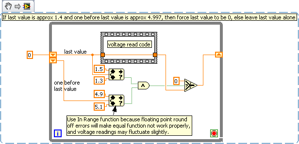
I have a potentiometer of 10 k, I'm reading through Labview. I got the signal to work and come through and everything, but there is a problem with the signal. The potentiometer is connected to a dial and returns a signal of 0-5 based on where the dial turns. So there 4.5 volts at 06:00 the signal gives 2.5 volts and 09:00. The question comes with 12:00. The signal can freeze to 4,997 volts for about 1% of the rotation and jumps to 1.45% ~ 1 and then goes to zero.
I'm trying to detect very fine when the dial begins to move and when it stops moving. I can't program a method to detect when the dial stops when the signal jumps around like he does. If you look at my program, I'm trying to set two criteria when the dial starts to move and when the dial stops. The problem is that jumps into the signal on the dial by midnight cause vi to prematurely close because the signal is erratic. Is there a way that I can change the signal of the device or anyone to think of a way of 100% can happen to these two criteria?
Thank you
Kevin
His character has written:
It's not a way I can just do a program that can logically interpreting the movements of the potentiometer? The value must go linearly from 0 to 5, and somehow use a VI or some form of logic to interpret if the value starts at 4.997 and then jumps to 1.4 instead of going to zero it must interpret this value of 1.4 as zero?
This will do:
Tags: NI Software
Similar Questions
-
Fluctuations of the Wi - Fi connection!
I bought a Toshiba Tecra M3 1.73Ghz with 802.11bg wireless in July of this year and it was working fine until about a month. At the start, my wireless connection saves 58MBps (and the "excellent" signal strength) but within 5 minutes, which drops drastically to 24 Mbps and even a skinny 1MBps sometimes. I also note that it disconnects and reconnects by itself, by new windows pop up notifying me of new connection frequently.
I checked my wireless hub and there is no problem with him. Indeed, my roommate have no problem with connection on his Apple G5 speeds. I also tried the obvious solution to move my right cell phone next to the hub, but that did not affect the connectivity.
Download speed fluctuates constantly and I cannot play games online such as counter-strike: Source, because I constantly disconnect and hang with my ping from 30 to 9999.
Is it a hardware problem or is there a software problem that I'm missing? If so, where I can take my laptop to get the sorted material?
Thank you
BenHello
In my view, it is certainly caused by hardware. In my opinion, you can swap the wireless card and then you should be able to use the WiFi without problem. If any of your friends have PCMCIA WLAN card, you can test it.
-
Why my MB Air decreases the wifi signal
My 2012 13 "core i5 MacBook Air running different operating systems will remove the wifi signal and it is getting worse. someone at - it a reason why?
How your MacBook Air running different OS version? However, the Wi - Fi signal fell to each version?
This always was a problem or just started to happen? Up to now, what did you do to try to solve?
-
After updating my iPhone 6 (9.3.4) the WiFi signal becomes very low! I did everything, but the problem does not stop! I don't a not update my other devices & their very good WiFi signals. Please help me solve this terrible problem...
Here's a tip for the user on the problems of Wi - Fi. Suggest from the top and bottom. Maybe one of them will help you.
(1) restart you device.
(2) resetting the network settings: settings > general > reset > reset network settings. Join the network again.
(3) reboot router/Modem: unplug power for 2 minutes and reconnect. Update the Firmware on the router (support Web site of the manufacturer for a new FW check). Also try different bands (2.4 GHz and 5 GHz) and different bandwidths (recommended for 2.4 to 20 MHz bandwidth). Channels 1, 6 or 11 are recommended for 2.4 band.
(4) change of Google DNS: settings > Wi - Fi > click the network, delete all the numbers under DNS and enter 8.8.8.8 or otherwise 8.8.4.4
(5) disable the prioritization of device on the router if this feature is available. Also turn off all apps to VPN and retest the Wi - Fi.
(6) determine if other wireless network devices work well (other iOS devices, Mac, PC).
(7) try the device on another network, i.e., neighbors, the public coffee house, etc.
(8) backup and restore the device using iTunes. Try to restore as New first and test it. If ok try to restore the backup (the backup may be corrupted).
https://support.Apple.com/en-us/HT201252
(9) go to the Apple store for the evaluation of the material. The Wi - Fi chip or the antenna could be faulty.
-
Satellite C850D-11 q keep loses the WIFI signal
Toshiba Satellite C850D-11 q BT Hub 4 Realtek drivers
I lose the wifi signal at least twice a day. Same message to loose / broken cable and reset the wireless card. Realtek has informed me that I have the latest drivers. The present is Realtek RTL 8188CE Wireless Lan 802.11n PCI-E NIC hub is new. With the help of BT, I now use the 5 GHz as the hub is on a shelf just below the laptop.
I don't know what to do else and thought someone here can get an idea of what to do next apart from the change of servers!
Thank you
LEA
I wait too long? Has decided to search for updated drivers. Goes up to 8.1 not 10.
Then decided to download the manual. Informed, there was one, but there is no way to access it. Message received this laptop modified 10/15/15. Well thank you very much for this. Message also States that "with this tool, you will get urgent information about updates for your computer. I clicked... Web page could not be found.
Large. Because buying a new laptop, but it will not Toshiba, that's for sure.LEA
-
The Bluetooth signal my audio is intermittent. How can I fix?
The Bluetooth signal my audio devices is intermitten, how do I fix?
It may be the audio device... However, try to reset the memory NVRAM and SMC.
Barry
-
Find and replace the name of the various signals of different value
Dear members
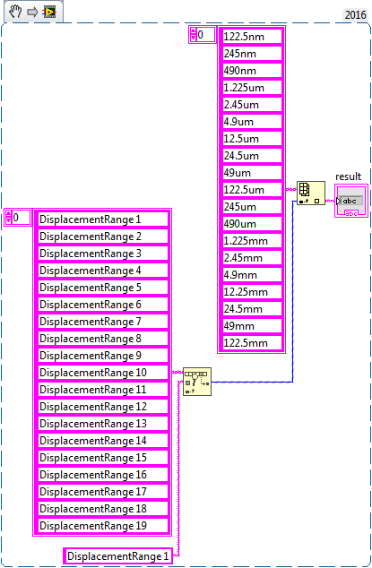
I run a program where I get the output signal ' displacmentrange 1 '...
"displacementrange 19" I need to replace this name with another name
for example
When come signals
displacementrange 1, it should show 122.5nm
displacementrange 1, he must show 245 NM
displacementrange 1, he must show 490 nm
concerning
Benoit zafar
Hello deutchland.
I hope that I have understood correctly, you can use find in table and then use the array index
-
Hello.
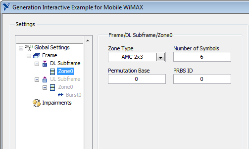
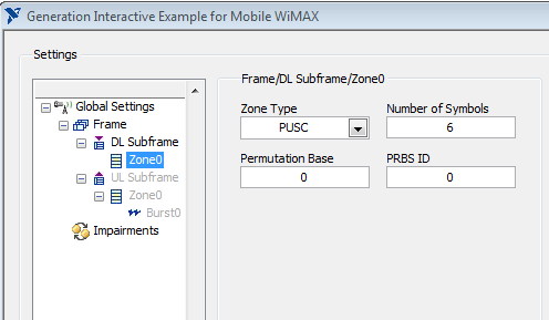
I use a VST OR to generate the WiMAX signal. I installed NO measure costume for Mobile/Fixed WiMAX 1.0 on the calculation. But I can't find any option on the front panel of the combination of the generation to enable AMC or PUSC for generated signal. This feature exist at all?
Thank you.
Hello sam2013ni,
That's all I see for AMC and PUSC. Look in "box Type".
Best regards
-
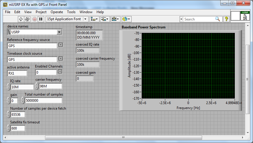
Acquisition with USRP 2953R of the GPS signal
Hi all
How can I configure a 2953R USRP receive GPS signals? I have an antenna VERT900 connected to the GPS ANT of the USRP port, but in the example VI 'niUSRP EX Rx with GPS', I can't reference this port in the field 'Active antenna'. I put only things like TX/RX or RX1 etc. Should what values I put in other areas as well? I know that the L1 band is 1575,42 MHz.
Hello
The example you posted shows you how to acquire an RF signal on the ports of the USRP with internal clock RF and sources of reference defined in the GPS.
To make it work properly, you must have a GPS antenna connected to the Terminal on the GPS device and installed in a place that receives a good level of GPS signal.
The other control of antenna on the schema defines the port on which to receive the RF signal.
If you want to capture and analyze the signal GPS (RF) itself, you can tune into the front-end RF (carrier frequency) at the right frequency of GPS band and connect your GPS antenna to the RF port.
You can use the simple niUSRP EX Rx continuous Async.vi in this case (but may not work due to the very low consumption of GPS RF signal)
-
Cross spectral power and consistency of the 2 signals
Hello
I try to get the cross-spectral power and consistency of the two signals. I should be able to get this:
"The cross-spectral power and consistency of these 2 signals have been calculated on a window (8.5 minutes) 1024-sample using the fast Fourier transform applied to the 3 overlapping of the panes of 512-sample in the window of 1024 consistency." In each pane, the data were the first linear straightened and with windows by using the Hanning (cosine) function before the calculation of the Fourier transform. The 1024 coherence window was so advanced by 256 samples (2.1 minutes), and the calculation repeated until all BDUS/interval of N - N series have been analyzed.
We used the product of consistency and the cross-spectral energy to weight these 2 effects in order to quantify the degree of the hitch.
I should get this chart type
The RR signal I straightened before that trying to get the power crossed with sampling freq = 2. And I put 2 ways to get it.
consistency too and later the product of the two. Im trying to get the spectrogram and watch later 3d like picture.
I have attached the vi.
Consistency is perhaps badly fixed.
Thanks for the help, guys.
Kind regards.
you made a few mistakes, example en by overhauling it you can't do the segments overlap, that's why you should go with a loop and the creation of a subset (and this is why I suggested para window ASD)
You must also set the indexing of the product release and do not concatenate, penny you released 2d end that you can use for 3d graphics
FS in the mathscipt should also be in hz, not in seconds, I told you the last time (he is shown in the help)
-
Desgning a VI that time / interrupts a film according to the input signal
Basically, what I'm trying to do is to design a VI who plays or pauses a movie according to the signal it receives. This VI will be used with an EEG device, and what I want to do is play the movie if the signal exceeds a certain threshold, and it stops if this isn't, in other words a VI that responds to neurofeedback.
As I don't have access to the equipment of the GET yet, I use a sine wave at the moment than the EEG signal in VI of the attachment in this post (which of course will be later replaced by waves of EEG recording), and what I want to do is to read the film if the signal is greater than 0 and put the film on hold if the signal is less than 0. Any help would be appreciated
Kind regards
varkong
I have included the code for the LV8.6 version.
Concerning
Prashant
-
NEITHER USB 4432 readable voltage i.e. the ASPM signal conditioning
Hello
For what I understood that the USB-4432 entries must read IEPE accelerometers report. Read a voltage signal conditioner of my sensor ASPM IE using the option 'IEPE-off with AC coupling.
Thank you
1. What if I use the 5th cahannel of
4432 read the square wave pulse width, i.e. the digital signal
tachometer using any function of sounds or labview software and
Vibration Measurement Suite. If so, how precis specific will be read
frequency (speed) compared to meter modules.Channel 5 is the same as the other channels of the 4432 except it lacks excitement IEPE and TEDS. I can't really say how "accurate", it will be at a faster rate because of the delta-sigma ADC. Someone else wants to chime in on this one?
2.
Is available to trigger analog acquisition of digital triggering. If so, is
It possibel to read all 5 channels togather in a single task.You're talking about!
3.
If there is only one PFI then is possible to trigger two
different tasks, i.e. a task of 02 strings with front amount and
a further task of 02 channels with the falling edge of the PFI even.There are 8 PFI lines, but can only be used on the device at the same time (it might as well be one PFI). You must have all the channels you want to raise in a task and use one as the trigger for starting digital PFI lines. (i.e. 'no'
 ... have a stain on the front and the other on the falling edge won't work, a task only by digital triggering)
Germano-
-
can someone tell me why I don't get the graphic signals in seprate
Hello
I'm stuck with a fundamental problem, in fact I use NI USB DAQ 6212 with my labview8.6, what I do is to get two different analog signals to ai0 ai1 simultaneously and showing them on two distinct waveform graphs, I use the split signal table index and both to solve the problem, but it is always showing me what a signal on the two graphs instead of show me two different signals on the two graphs. can any body tell me what I'm going to do now, is there a problem with my DAQ hardware I brought just a few days ago, or should I include something in the software? criterion vi is attached.
waiting for a good answer
-
frequency of the digital signal 6009
Hello, how to generate the digital signal with frequency 50 Hz using NI USB-6009?
You can take a look at this:
Can I use a generation of impulses with the counters on the USB-6008/6009 case?
-
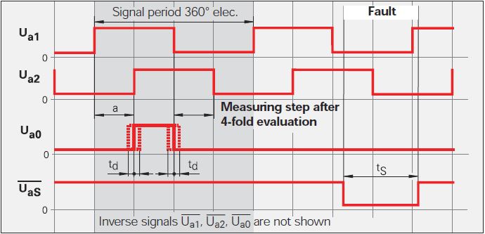
Count the edges of the 2 signals TTL (Heidenhain linear scale)
Hi all
This is my first post here. :-)
Currently, I'm doing a VI to be used with a linear scale. The linear scale gives 2 TTL signals that have an offset of 90 °. The change in distance of the linear scale is given by counting the fronts and edges of the two signals. See the following image: Ua1 is signal 1 and signal 2 Ua2. You can ignore the other signals.
Now, I want to count the 4 edges in order to translate the 2 signals in the distance. This means that I need advanced two counters for Rising-rising, Rising-Falling Falling Falling, falling on the rise for 2 signals. I tried to do 4 points two counters in LabVIEW but that of course does not work, because an acquisition of data can access the card TTL or I did it wrong.
Once I have to handle this, I also want to understand the meaning.
My card TTL: NI 9402
My electronic Heidenhain interface: 100 IBV (http://www.heidenhain.com/fileadmin/pdb/media/img/598_160-23.pdf - also at the origin of the image)
Hardware configuration: linear scale-> IBV (Elektronic Interface)-> NI 9402-> LabVIEW
Signals: Analog 3-> 3 TTL-> OR 9402
I hope I do not double post. Any help would be greatly appreciated.
I used Heidenhain linear scales in many applications.
As stated in the previous post, the output of your balance is as a quadrature encoder. Therefore, you must use an entry of the DAQ card counter to measure the position of the scale.
The desired X 4 mode is done by the meter itself (not possible with some old maps of OR).
As starting point, see measure angular Position.vi that comes with examples of LabVIEW. On your linear scale, change the type of the polymorphic DAQmx create channel VI CI linear encoder and etiquette of pulses per revolution at a Distance by pulse.
Feel free to post back if you need further assistance.

Maybe you are looking for
-
Updated - why does Devil Kapersky and how long will be Kapersky wouldn't go again.
Updated - why does Devil Kapersky and how long will be Kapersky wouldn't go again. I don't want only it off too long because it's my security protection
-
PXI communication problem of NOR
Hello I use the chassis NI PXI-1042 q with NI PXI-8196 embedded controller, I couldn't contact my NI PXI PCB (NI PXI-5124, NI PXI-4472 etc.) Currently, I installed NI LabVIEW 2010, NI MAX 4.3 and WINDOWS XP operating system Concerning Raj Kumar S
-
RAN TESTS PRINTER, THE PRINTER DOES NOT PRINT. WENT TO HELP FIXIT CLICKED ON DO NOT FIND ANY PROBLEM.
-
Lost start menu programs and photos from picasa
I have Windows XP I lost somehow programs to the start menu and the images lost in my Picasa. How can I fix it
-
HP TouchSmart Desktop PC 600-1120: disable the mouse wheel click
Hello I have a HP TouchSmart 600-1120 Desktop PC, and I want to disable the click of the scroll of the mouse wheel, so it only scrolls up and down and is not clickable. The click is so sensitive, it's difficult to scroll without accidentally clicking