frequency counter
Mr President, our project is on the design of a "eddy function current sensor for measuring respiration contactless".we had designed so far to 12 MHZ output colpitts oscillator, this frequency is converted into square using a schmitt trigger pulse. Now, we want to know if it is possible to count the frequency of 12 MHZ in lab mode? What is the maximum and minimum, frequency counted by lab view?
You will need some kind of hardware, likely N.I. DAQ. What you are going to use or you use?
Tags: NI Software
Similar Questions
-
Hello
I have a power meter which provide the USB driver and a Labview program to get the data and NI USB-6221. The project I am currently working on the needs of:
1 acquire two signals (inputs of simple tension), pressure frequency KHz
2. acquire a flow signal, the output signal is 0 to 5V pulse, each pulse means 0.4 ml volume. So I use a voltage inflows to count impulses in certain period of time (in this case, 1 S) for water flow. ; KHz sampling frequency and the 1 Hz update rate
3. acquire a signal of engine speed. The output signal is pulse square wave whose frequency is related to the speed. I use a REIT port to measure the frequency. Sampling rate: Auto
4 give output voltage sine or square wave, I use AO do that.output rate: Auto
5 acquiring by VISA electricity meter data. Data update rate: every 50ms
Currently, all the 5 tasks work well separately. But when I put them together, some signals are beginning to hang, for example, pressure signals sometimes give nothing.
Another problem is the data record. I programmed the VI in such a way that whenever I press the button 'save start', he begins to record data and save them in a .cvs file. For some reason, I always get only the data in the first table. Coult someone help me? I download my code as follows
Hello
What I meant by open, write, close. For any type of file you are using.
Open the file, which produces a reference, then put the mention in a registry to offset.
Write data, using the function write (for this type of file) and the reference.
When you are finished, close the file reference.
Writing in the spreadsheet opens, written, close all at once. It is very good for this type of application.
***
The issue of the loop is more general. I would like to say first of all, I want to say that since each loop works on its own, it is own VI, and that this program has put all this into a single VI, which has a method to solve the problem is to disable all the loops and allow them one at a time to see if there is a culprit responsible for.
Using multiple loops executes the code at the same time, and some loops would be cycle faster than others, especially if some of them are loops just as they are.
Communication between the loops is a test to the address if necessary.
Running all these signals through different loops DAQ must also be examined. Don't know what questions are for read and write somewhat randomly in the channels.
-
Help the spikes of voltage high frequency Counting
Equipment: NOR USB-6229 (250 ksps / s analog in., 16 bit DAC, 32-bit counters, and internal clocks)<= 80="">
LabView 14
Problem:
I have an experimental app where I need to count the points of tension (entire #) caused by electrons striking a sensor. These tips can be as frequent as 500 000 heads of charge/sec. The tips aren't going to be the same tension every time, but they will be visible above the noise, so I need allow the user to select a threshold voltage that triggers a true count rather than the tips of noise.
Attempts:
To count such a high frequency, I gather that I need to use a counter entry to read fast enough, HOWEVER, I wasn't able to find a way to define a threshold of voltage for a counter entry because I think they expect a TTL signal anyway, which I won't. To set the threshold, I realize reading of analog input can be triggered at a point chosen, which is great, but the Analog Input sampling rate is only 250 kech. / who will not catch count each in my project.
I have a program that uses the channel count edges and it is accurate to 3% of the # expected charges. I was looking at him just with a function generator and the program does not count unless the signal voltage is higher than V 2-3 who does not work for my application. I'll post what I have. Someone know how to trigger at certain levels of tension using counters, or know a way to filter through the noise to get real tips?
Thank you!
You will need a device with a sampling rate of greater than 1 MHz analog input or you will need an external reference. With the external comparator, you can use output to set the threshold, although the user would not be able to see the signal or the threshold, only the analog account result.
Lynn
-
Error-200141 with low frequency counter measures
Hello
I'm trying to measure the speed of a rotating shaft using a laser tacho Keyence and a counter on my PCI-6601 entry.
I can't reach my vi, but I join a PNG of the section of code.
Background:
-L' tree turns to ~ 6000rom
-The counter is updated frequency measure ona climbing on board. There are 9 rising edges per revolution of the shaft.
The problem:
-If I put the vi to capture a small number of samples, it works very well.
-If I put the vi to measure the samples more 200141 occurs error "data has been overwritten before it can be read by the system.
-The number of samples, I can get without problem varies. 200 seems reliable enough. Sometimes I can get 1200, sometimes 600, sometimes 150.
-I would like to be able to get samples of ~ 2000.
-If I try to get samples continuously, I encounter the same problem.
If anyone can help with this problem it would be greatly appreciated. This is something I continue to flow upward against but so far have been unable to rectify. I'm sure I'm missing something, but I have no idea what.
Thank you very much
Martin
version 8.2
-
Frequency counter measurement crashes when you're away point zero (NI USB 6343, error-200284)
Members of the Forum,
I have problems with a measure of the frequency on a DAQ Mulitfunction of NI USB 6343 X series. I use the meter 1 (door axis for frequency signal, PIN to DGND 82 77). The couple HBM T10F flange that I use (powered by a power supply of 24V) emits a signal of frequency between 5000 and 15000Hz with 10000Hz being the zero point. Couple flange has a capacity of 5kN.m (15000Hz = 5kN.m; 5000Hz = - 5kN.m).
I have been using the VI attached for a few months now without any problems. Now, the VI works fine as long as the couple remains inside a few hundred Hz of the zero point. However, when the frequency increases further reading couple begins to freeze and finally I get either of these two errors:-200279 or-200284 related samples is not not available. I noticed that the light on data acquisition close compromise during these periods of frost.
Here is an example step by step my problem using cal shunt of the flange of the couple:
1. I have run the VI and couple bed properly around 10000HZ (Active light, indicator light ON)
2. I have apply the excitation of 5V to the shunt cal and frequency climbs to about 50% of the ability to couple brackets (as it should)
3. as soon as I remove the excitement 5V playback freezes and the light on the acquisition of data.
4 if I apply the 5V once again, until the timeput occurs, the led turns on and the acquisition of data reads the signal correctly.
This type of problem would be more DAQ-related or is it the flange of the couple itself.
Thanks in advance,
Mike
Solved.
I did some troubleshooting this morning and it turns out that the vibrations of the system had not tightened a screw that was connector to the stator flange torque causing a bad electric signal of the torque flange itself.
Everything works fine again.
-MB
-
Read frequency counter HP/Agilent 53131 via GPIB using c#
The only thing in your code is a reading? How do you set up the meter manually before taking the action? What is the arming mechanism? What is the opening time? What is the sensitivity/resolution?
I think the problem is with your configuration and can respond to study the manual or by asking Agilent.
-
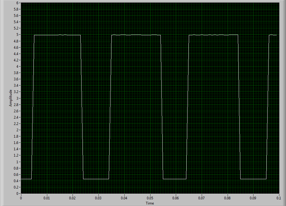
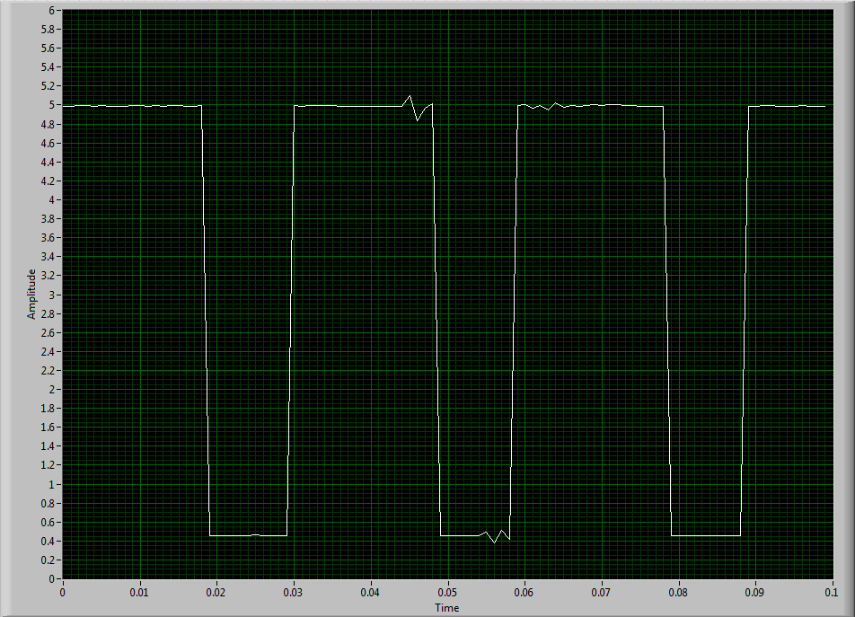
NEITHER USB-6343: erratic low frequency 1 counter measures
Dear members,
I'm looking for help with a measure of low frequency counter. I tried to make it work for a week or two, but I keep getting erratic measures. It will read the rpm properly for a second or two and then it will give a ridiculous value on the order of 10,000 times the correct value. I can not get a constant value.
I use a DAQ series X NI USB-6343 multifunction with Geartooth Honeywell GTN1A111 sensor. I enclose a sketch of the wiring configuration. I think that it is correct. Sensor output to the door of the meter.
To try to solve this problem, I hooked the sensor to an analog input channel to make sure that I was getting a TTL signal by sensor. I noticed every once in a while I'd see a glitch of little noise in the signal and I guess that's what is causing my problem with the meter. I inserted two waveforms of the sensor signal (one with the clean signal) and the other with the glitch of noise. My understanding of a TTL signal meter channel will examine LO voltage when it is below 0.8V and HI when it is larger than 3.8V. So I really do not understand why these little glitches could be the cause of the problem because they are well below and above 0.8V and 3.8V, respectively. I think that the noise comes from a frequency converter used to drive the engine. I tried the system as much as possible of the Earth.
I guess I'm looking for another approach. I could potentially use a digital filter to help with noise? The glitch is in fact the problem or I forgot something. The VI in question is attached.
Thanks in advance,
Mike
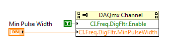
Have you tried to set up a digital filter yet? Obviously the seeds are collected as an additional transition (the method of low frequency counter 1 measure the period and then reverse, so a short glitch would record as a very high frequency).
You can enable the digital filter with the following property node:
Min pulse width is guaranteed pulse past the filter, so it should be low enough for the real signal is guaranteed to pass through (but high enough so that the glitch is always rejected).
Best regards
-
PXI-6133 Pulse frequency output and input with DAQmx
I am trying to set a pulse meter output frequency task and read this signal with a frequency counter input task input pulses. I use a 2 PXI-6133, each connected to a BNC-2090 case has. I want to output a square of a certain frequency with the task frequency meter pulse output and then read the frequency of this signal using a task of cost input frequency. I don't know how to property set up these tasks, or how to define which device to use for each heap. I don't know what terminals on the BNC-2090 is the counter of entry/sortient channels correspond to them because that is not displayed in the documentation of the PXI-6133 or documentation of BNC-2090.
Please see the attached VI for my attempt to put this in place. Currently, I get two errors:
(1) error-200452 took place at the property Node DAQmx channel meter Test - referred to as property is not supported by the device or is not applicable to the task.
2. the error-89136 at DAQmx Start Task - specified route cannot be met because the hardware does not support.
If I remove two channels of property DAQmx where I try to put the terminals for the counters, while the program is running, but then I know not what terminals on the BNC-2090 meters are connected to! This causes the DAQmx read for the cost in the tasks of frequency to timeout because it does not detect a signal.
I would really appreciate the help to properly configure these tasks and determine what terminals on the BNC-2090 case has the task of counter will work on.
I see a few problems in the code originally:
- For your CI task, you type is defined as a counter entry > frequency. But on the node property of DAQmx channel for this task, you modify the CI. Property of PulseWidth.Term. It should be CI. Freq.Term. set the entry regardless of the PFI line you do not want the input signal on. Tip: you don't have to type the name of the device in at all. Enter "PFI0", it's the same as "DevN/PFI0" since the unit has already been specified in the DAQmx Virtual Channel Create function. The name of the device, leaving aside will make your code more flexible where you decide later to change the name of the device.
- Maps of the S series, such as the 6133, do not have the same flexibility to change the output terminals of tasks of meter you might find with M or X series device. Page 83 of the S series manual watch what signals can be extracted to PFI lines - Ctr0Out is not one of these. Instead, Ctr0 out is, by default, pin 2. Cabling to a BNC-2090 6133 is certainly difficult to understand out (probably because the 2090 was designed to work with the materials of the E and M series), but if you compare the pinout of a PXI-6255 0 with the 6133 pinout connector, you will notice that they are essentially a match 1-1. Pin 2 is PFI12 on the 6255, so I assume the same for the 6133. All this to say, Ctr0Out always appears on the pin 2/PFI12 for the 6133 and you therefore cannot change the output terminal that your code is trying to do, having for result error-89136. Remove this node from the property altogether and the error should disappear.
-
Count the number of rising edges in table 1 d
Hello
I wanted to measure the frequency of a pulse signal using a MCC DAQ via libraries ULx in Labview. I have two methods to do this:
1. use the analog inputs:
Since data acquisition has only 1 ADC, I use a commune VI acquisition for all channels and create a multi-dimensional array with different channels in rows 0-15. Then divide them by using the function "Array Index". I think this split removes the parameter 'time' to the wave, since it is now a table 1 d. But I already know that there will be 1000 samples each 100 m everything I want to do now is to count rising edges using a function and divide it by the 0.1 to obtain the frequency in Hz, but I don't know how. Can anyone help?
2. use the input frequency meter:
Because I can't use the DAQ assistant, I have to use the CI frequency-> counter 1ChanNSamp DBL 1 d in the ULx library. There is no reference to take aid to and I do not know if this method is good. I have no way of knowing since I do not have a signal generator. In addition, it does not work so far.
Help, please.
Thank you!
Thank you.
I note in your first post it is seems to want to get readings of speed about 10 times per second. To get a resolution of 1 Hz frequency direct count you need to get at least 2500 counts in a range of counting at the highest frequency. This means that you need to have at least a second. Measures of the time are another option.
Some preliminary calculations:
Period at 2500 RPM = 2500 Hz is 400,000 Americans.
Period at 2499 RPM = 2499 Hz is 400,160 to the United States.
You need to be able to resolve a difference of 160 ns period. To do this directly requires 6.25 MHz sampling rate. It is 25 times faster that your DAQ card can enjoy.
What other options are there? Consider only your Information.vi extract. He uses techniques of Fourier transformation and interpolation to find the frequency of a signal. I set up a quick test VI to check this. Using a sampling rate of 10 kech. / s and 1000 samples per read (10 reads per second), it has easily resolution of less than 0.1 Hz at both ends of the range of speed and largely independent of the amplitude. This is the way to go.
Lynn
-
Use the OID and counter in DIAdem
Dear Sir
I can perform a task I and medium AO DIAdem DAC and my DAQ hardware. But when I try a task of DI and entry (for the measurement of the frequency) counter, problem, whenever I start the CAD module, anything happen but a snap short, it stops just before there is no measurement data. The DI and the entry of the virtual channels counter works very well in DAQmx, and I can see them in DIAdem. I missed something?
Concerning
Somewei
... other images
-
PCI, I / AO at a different frequency
Hello
As a newbie, I met a problem when I tried at the entrance and the analog output signal at a different frequency.
I followed PID-control - Multichannel .vi to build a control program, so input/output can be synchronized. However, the project requires that the frequency of I be tenfold of the AO. I could re-write the while loop to make the output value constant for 9 of 10 cycles. However, in my view, it is simplest way to do.
Anyone provide an example?
Thank you in advance.
Sincerely yours
Ming
lmuri wrote:
Hello
As a newbie, I met a problem when I tried at the entrance and the analog output signal at a different frequency.
I followed PID-control - Multichannel .vi to build a control program, so input/output can be synchronized. However, the project requires that the frequency of I be tenfold of the AO. I could re-write the while loop to make the output value constant for 9 of 10 cycles. However, in my view, it is simplest way to do.
Anyone provide an example?
Thank you in advance.
Sincerely yours
Ming
Hello Ming!
Please use the Forums of NOR. You'll be happy to know DAQmx allows what I/O tasks such as these to be not run not only at the same time, but at different rates.
The problem with the solution that you have imagined is that this implementation will remove the delegation of tasks to the hardware level, and your program would become software-driven; This becomes a problem when you perform tasks of acquiring data at very high speeds as it becomes limited to the speed of your operating system (OS).
You can coordinate your tasks to operate synchronously and perform the output and the acquisition at different rates by creating a maintask. This means generally that you configure a task by DAQmx that keeps a clock frequency and you create tasks that use this clock frequency, or a division thereof, to exploit to their own individual frequency. This facilitated not only the execution of DAQmx tasks synchronous but also provide a material entirely focused on the solution of performance maximimse.
Thanks to LabVIEW, if you go to help > examples find to open the Finder of example of OR. If you are browsing material input and output > DAQmx > synchronization > multifunction > Multi - multifunction - Synch Dig read write with Counter.vi, you will find an example of how to set up a counter as a master of the task to control the operation of operation both a reading and writing . (This example shows a digital but implementation may be easily replaced by analog).
By setting the meter to the maximum frequency rate that you will require for your task (in this case, the speed at which you want to copy values) and apply it to the output of the SampleClocktask, you will drive the clock output task with the counter as the clock source. You can then use the meter as the source of the SampleClock for the task of entry, however to set the rate at any division of the driving frequency. In the case of your example, you can set the bit rate to 0.1 times the frequency counter to acquire a 10th of the rate.
If you want to acquire at the same rate, but only to retrieve values on the 10th of the speed, this same solution can be configured to produce instead a trigger to return an acquisition in the buffer. With a master synchronizing the task, the possibilities are endless!
I hope you find it useful, and if you need a precision more do not hesitate to let me know. Have fun with your DAQ!
-
Hello
I m working on acquiring data usb 6341 and facing a problem. When I use two frequency counter in the same program, it fails to calculate the frequency (frequency meter task crashes). but when I use only one frequency counter works properly.how can solve my problem...?
-
How can I take several consecutive steps of a frequency meter and keep the previous measure?
I'm sorry, I'm very new to view lab and I am taking several consecutive steps of a frequency counter. I place the sub measures VI and the indicator with a loop and then set N to the number of iterations. The problem is that I don't get a box in my display board when I need all the previous measures taken for this iteration. Thanks for your time.
Your data inside the loop to an object outside the loop of the wire. Right-click on the tunnel and turn on indexing. You will have a 2D array (if your data was in 1 d) where each row (row or column, you will need to understand) is the result of the iteration.
You can separate the 2D table by using the Index of table vi.
-
Physical connections using 4 counters with NI 9411 cDAQ chassis 9178
Hello
Currently I have a NI 9411 module in a 9178 cDAQ chassis. I use 2 meter to read the frequency measures.
The NI 9411 pinout diagram (see pdf file attached to this post), here are the links that I did:
CTR 0 SRC, pin 1 ground COM
DOOR of the CTR 0, pin 2 to the first signal of frequency
CTR 1 CBC, PIN 6 COM/ground
CTR 1 DOOR, pin 01:53 frequency signal
The problem now is that I had like to use meters of 3rd and 4th in my 9178 cDAQ chassis, but I am confused how to wire
frequency signals in 3rd and 4th, because CTR2 GATE is pin 1 and GATE CTR3 is pin 6. Can I change the assignment of pins
to use the other pins in the NI 9411 module for frequency counter measures? I didn't understand how to do this in MAX
Configuration.
Thank you
Anna
Hi EETDer,
Using 'C-Series Signal connections for counters that you found is a good resource. One thing I want to point out, that's a measure of the frequency on a single meter, simply connect the source of the signal up to the door of the RTC. Internally, the module will forward a database internal time appropriate to the source of counters, so DO NOT want to connect the Source CTR to the mass. On your device, you will be just wire each signal to the source of the meter, so only utilizting pines 1,6,3,8 for your 4 frequency measurements.
-
HP5350B does not not at the controls GPIB
Hello
I have been using the HP5350B, an old frequency counter HP for a remote control application. I use the GPIB commands to send and receive messages from the instrument. I have attached the screenshot of code that uses a GPIB read block to read the value of the instrument. Earlier, when I used a connector of the GPIB-USB-HS, I was able to get the values you want by using this code. Recently, I got a PCI-GPIB, I installed in my computer and since then have tried to read measages of the instrument with this card in the computer, but I did have a success to reading the value of the instrument using the same code. I get the error shown in the attachment. The only difference I found between the GPIB-USB-HS and card PCI-GPIB is the change of the address of the instrument for GPIB1::7:INSTR(for_PCI-GPIB_card) to GPIB0::7:INSTR (GPIB-USB-HS), who appeared in NI MAX.
Now when I connect the GPIB-USB-HS to the computer and try to communicate with the device with the same code I am unable to reproduce the results I was getting earlier. I'd appreciate your feedback to help me solve this problem.
Thank you
Vivek
Directly from the LabVIEW help file
When there are several controllers GPIB that LabVIEW can be used, a prefix of the string address in the form ID:address (or ID: If no address is required) determines the controller that uses a specific function. For example, to set the GPIB 2 controller to talk to a device at address 3, use the prefix 2:3. If a controller ID is not present, the function by default controller (or bus) number 0.
You have changed your hardware configuration, such as '7' is no longer unambigeous. Use ' 0:7 ' or ' "1:7".
Maybe you are looking for
-
Need to download .zip without enlarging
How can I download via Safari .zip files and there not open (expand) the file? These zip files are designed for a different system, and uncompress loses the special attributes packed with files. So just re - compress the directory is of no use. I ne
-
Click on TouchPad does not work properly
I use laptop HP Pavailion G6 with product LR774PA #ACJ number. Or locking the touchpad doesn't work or the click of the toucpad functionality. Even if I am able to scroll using toucpad. I tried to uninstall reinstall a driver for the touchpad. Every
-
After installing new color cartridge for my Canon MG2100, I am unable to re - align my impressions
How to make a PAGE of realignment, after installing the new color cartridge? The impressions that I get are blurred :( Installed cartridge was Canon 241xl color. Looking forward to a quick response, thanks!
-
How to disable the pop up sound activation module
to start the computer, the sound activation module appears. have tried to disable said pop up but failed. any advice?
-
After re-formatting computer, cannot run Windows Update on Vista
Well, I recently re-formatted my computer. I bought my computer through Aaron, and they never gave me a recovery disk, until a few weeks ago. My computer was originally came with Windows XP and now I have Vista. Now, I can't start my windows update.