counter multiples or usb 6341
Hello
I m working on acquiring data usb 6341 and facing a problem. When I use two frequency counter in the same program, it fails to calculate the frequency (frequency meter task crashes). but when I use only one frequency counter works properly.how can solve my problem...?
Tags: NI Software
Similar Questions
-
Amnesty International and counter sync + USB signal stream (USB-6210 vs USB-6341)
Hi all
I'm at a stage of identification of a material suitable for the following tasks:
- 5 analog inputs (AIs) of reading at the same time, tensions at a rate of kSps (at least) 10,
- application captures 2 inputs using timers (detection of contours with timestamps), square wave entry with duty ratio of 50 percent and about 1.5 kHz frequency and variable pulse width / frequency (from 2 sensors hall, representative of the DC motor rotation speed and direction, quadrature signals), resolution of timestamps should be (at least) 50 ns,
- AIs and counters should behave in a deterministic way, and must be synchronized in a way,
- data to be transferred via the USB port of a host computer with Matlab Data Acquisition Toolbox (unfortunately not LabVIEW).
I've identified the long USB-6210 USB-6341 and potential candidates of material to accomplish the above tasks, but after reviewing several documentation and the topics of the forum, I'm still a bit confused, if both are fully working and my approach described below is not working properly.
Counters: I intend to use the internal time base available 20 MHz as being the source of meter to get into account the resolution of timestamp 50 ns. External impulses hall are used as sample clock (about 1.5 kHz, see above). As the pulse width varies, the sample clock is not constant.
AIs: Using a 10 kHz internal clock signal derived from the time base of 20 MHz for timing and analog inputs (trigger) start-up and counters simultaneously material should translate into the required synchronization and deterministic behavior.
It work? Other recommendations?
Next is the USB data transfer: all HAVE 5 and 2 data entry of the meter must be correctly transferred to the host computer (the corresponding rates are shown above). USB-6210 is capable of 4 USB signal flow, device USB X range (6341) offers 8 of them. Unfortunately, I could not understand the exact meaning of the expression "signal flow" still. Do I need 1 flow of input signals (would be 7 for my application described) or 1 stream for all analog inputs and 1 for counter inputs (lead 2 streams for my request). Is there no further details on this approach (more than Streaming of signals of NOR) USB signal flow?
Any challenge to the described application that I might have forgotten? 6210 USB seems to a very limited number of entry PFI, maybe even too low for my meter participate application?
Looking forward to your comments and advice.
Concerning
jAwA
1. I recommend the X-6341 series on the M-series 6210 sake of counters/timers. It is more of them, and each of them is more capable. It can also have a great FIFO embarked for meters that may be important in certain tasks, although I don't think that you currently deal with one of them.
2. your general concepts on timing & sync are satisfactory. You will be able to share and to route signals that help ensure synchronization and determinism between the timestamps for your various tasks. Note that for meter entry tasks, you need set up the trigger 'Arm Start' rather than the regular start trigger.
3 is not authoritarian, but I believe that the flow of signal # will correspond to the tasks #. For you, it would be 1 task of HAVE and tasks CI 1 or 2. (Not clear if you have 1 Encoder with 2-channel quad that would require 1 task of CI, or if you have 2 encoders with 4-way quad).
4. pay attention to the hall effect signals that are not virgins. Digital filtering is available and probably better on the X-series, the series M.
5. strictly speaking, edge detection is a type of digital input task that produces samples but no timestamps. Ideally, I would like to parallel wires on the two digital inputs for the entries of detection and counter change to position quadrature decoding. Then I would sample the counters Encoder 1 or 2 using the internal pulse 'event of detection of change '. I would create another counter timestamp change detects pulses as well.
-Kevin P
-
connect multiple signals card NI USB-6341
Hallo,
I'm trying to connect the signals of several NI USB-6341 map.
This map has 16 channels but not 32 pins available.
for example if I want to connect a signal on channel 0 I connect to pins 1 and 2 and for channel 8, I have to connect to channels 2 and 3.
If I connect only channels 0-7, it works but if I connect channel 8 I do not get the real value of this signal.
any ideas?
Thank you
Theodore
Theodore,
This sounds like it should work. Basically, you use AI0-3 and AI8 - 11 for your four differential signals. This leaves you AI4 - 7 and AI12-15 free for single operation is complete. The configuration of the terminal can be defined on each channel. To do this, you can use DAQmx create channel several times to add channels with a different configuration to your task. If you need details on it, let me know what environment you'll be programming, and I'll see if I can provide more specific assistance.
Hope that helps,
Dan
-
Measure the time of the rising edges of a digital stream using a USB-6341
I have a DAQ USB-6341 map.
I use Measurement Studio (writing code in c#) on a Windows 7 computer.
I'm relatively new to the DAQ cards, programming, so I could ask something that is obvious (sorry if this is the case).
I went out a stream of digital pulses to an analog output channel. I wired this channel to one input of the meter channel. I am able to measure the number of edges upward to the inlet of the meter channel (since the digial flow is continuous, the number of rising edges increases with time).
I would like a time stamp of each rising transition and I like to keep these timestamps in a table without ever growing (or maybe bin these timestamps in a histogram).
Set up the meter channel to provide the timestamp data? (rather than just count)
Thank you for your help.
WRB,
The meter must be able to measure the relative time between the different edges of your signal. To do this, you will take care to set the meter to measure time. It will measure how long a full period of your signal takes. You can configure edge that you want to start with. You'll want to set up your timed 'implied' measure. This sets up the meter to automatically take action whenever a period is over. While it's not exactly a timestamp, you can find the distance between two edges by adding the time periods between the banks in question.
I see another technique that you can use. This would put the counter to edges of County one of the basics of time of your device (it has 100 KHz, 20 MHz and 100 MHz bases long). Then configure the task to use your signal as a sample (configuration to use rising edge) clock. Whenever the song occurs, you will get the number of ticks ticks selected timebase that took place at that time. One thing to note here, however, is that the counters are 32-bit wide, so your code will have to manage the overthrow of this charge if you are using a fast time and base running for long periods of time.
Hope that helps,
Dan
-
problem with / s digital correlated on USB-6341
I'm testing an application that fact/s digital correlated, written in C++ with a USB-6341. I use NEITHER-DAQmx version 16.0.0f0.
Because this application will be used by people with a variety of different DAQ hardware, I tried to write it to manage a lot of contingencies. Then when I put in place a DIO task correlated for the release, I'm trying to determine the width of the channel:
uInt32 dataBytes;
If (NIerror = DAQmxGetWriteRawDataWidth (h, & dataBytes))
On my USB-6341 dataBytes returns 1, so I try to write data using DAQmxWriteDigitalU8(), but which returns an error saying:
device USB6341:-200565: specified the digital channel contains more bits than supported by the 8-bit version of DAQmx Port write.
Use the version of DAQmx Port write who takes in charge the broader digital ports.
If I remove the test and force it to use DAQmxWriteDigitalU32(), then it works.
I'm afraid that if I try to always use DAQmxWriteDigitalU32() I may be wrong with other devices that do not support 32-bit channels.
Is this a bug in NOR-DAQmx associated with USB-6341? Have I misunderstood something about how it works?
John,
It seems that it is a known issue with DAQmx and a corrective action request was filed for this problem. For now, using the DAQmxWriteDigitalU32 should work fine if the device has ports 8-bit or 32-bit.
-
USB-6341 not on the list of simulation devices
I want to create a USB-6341 siumulated, but this model is not in the list of available under devices simulated in MAX X series devices. I don't see in the devices of series X available for the simulation are PCIe devices. I have MAX 4.7, 9.1.5 DAQmx and LabVIEW 2010. I did this on other computers running older versions of the software and saw this device on the list, so there must be a software component that I have installed, but I can't understand what it is. Any suggestions?
Richard
Material of the series X USB were not released before DAQmx 9.2; you need at least this version in order to use a simulated.
-
Computer does not start when connected to USB-6341
Hello
When my board 6341-USB is connected to my computer and the device is on, if I start the computer the USB-6341 module, the computer crashes before windows starts.
I said that the computer is an HP with Windows 7 64 bit computer. All Boot on USB configuration are disabled.
Is it possible to start the USB-6341 before the computer or not?
Best regards
CFOE
Hello
Unfortunately with my HP computer, because the HP hardware, the computer cannot be started if USB-6341 is connected and powered.
Best regards
CFOE
-
Model generation with USB-6341?
Hi all
We have developed a software quasi multifunction 'device-independent '. This sw is capable of generating the sequence shot timed with the device really used. Up to now, we have used devices PCI-6025 and USB-6221, but now we bought a USB-6341 and when I try to use a message of 200565 error pops up: "specified digital channel contains more bits supported by the version 8 bits of the Port DAQmxBase write.» Use the version of DAQmxBase Port write who takes in charge the broader digital ports. Minimum size of write in bits: 32 "
I tried to change PORT0, PORT1 and PORT2 but only PORT0 is legal for the model generation process and it requires DAQmxWriteDigitalU32 function...
I don't understand why.a / 6341 contains 24 DIO lines
b / only 8 DIO lines are clocked by materialThen there are 24 DIO lines (i.e. 24-bit 32 no!), but only 8 lines are timed by the hardware and I want to use only this 8 lines for model generation!
Our whole software is based on 8-bit pattern-berries (writeArray type is "uInt8"). If we cannot use this structure, we must rewrite dozens of functions...So, how can we use the function of DAQmxWriteDigitalU8 with USB-6341 or what can we do?
Thank you
-George Cs.-
Dear George,
It is an interesting question, which may seem a bit unintuitive at first. The main reason for the 32-bit write operation (although the USB-6341 has only 24 DIOs) is that the functions and the driver support other devices too. As you can see in the manual of the unit (http://www.ni.com/pdf/manuals/370784d.pdf) X Renault series supports digital IOs up to 32 bidirectional signals.
To keep things consistent exploitation of 32 bits is required even if you use only a subset of the available ports.
I hope that this helps to explain.
Best regards
-
Hello all-
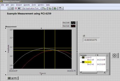
I'm looking for more help with an acquisition of data USB-6341 X series. I am trying to acquire samples N at a specified sampling rate, using a very basic interface of Labview 2012 on a Windows 7 machine - front panel is a waveform graph, and the block diagram is the DAQ Assistant wired the chart (I change the number of samples and the sampling to the DAQ Assistant interface). If I choose the number of samples and the sampling rate that multiply on in 10 seconds or less, I have no problem. 10 samples, 1 Hz? Ok! Samples of 10K, 1 K hz? Don't panic!
If I chose a number of samples and the pair of rate which is equivalent to more than 10 seconds? Error 200284, 'some or all the requested samples aren't yet vested."
Continuous in Labview, or looking at the test panels, testify without problems. The displayed voltage works with the digital display on the instrument that I'm sampling, so other that do not take data for more than 10 seconds, everything seems to work.
Source of any reflection on a problem or difficulty?
Any help will be appreciated.
John
Additional parameters of timing under the "Advanced Timing" tab and increase the time-out...
-
How do you count multiple columns of a field in a table
How do you count multiple columns of a field in a table
Select count (*)
of user_tab_columns
where table_name = 'YOUR_TABLE '.
-
Synchronous channel multiple acquisition USB-6259 (phase measure)
Hello!
I want to create a user-signal (1 k at 20 kHz) in SignalExpress, generate it with the case NOR USB - 6259 BNC and measure with the same device after that the signal has passed a DUT I need the answer for a fixed term.
For the moment, I'm trying this: I connected the output via a Y-coax analog (length 1 meter) to TWO analog inputs.
Because the input channels have been grouped with the add a channel button, the data acquisition should occur almost synchronous.
However, sometimes the phase response is zero (cause as expected the two signals must be equal), but sometimes it "jumps" (especially when I am running the new project) and increases or decreases linearly on the frequency (so there is a time difference between two measured signals).
I don't think that running is the problem here, because referring to the manual, it's about some µseconds and I have not yet change the range of voltage between input channels. Furthermore, the magnitude response is fine.
I has not yet perform to synchronize the input channels with the output of the channels either, but first I would be recognizing a solution for the entry-entry-synchronization, (I don't mind if it is implemented in LabView).
Thanks in anticipation, Daniel
Hello Daniel,.
the M-Systems Series DAQ using a switch to sample multiple channels. So you have to take the time to switch into account when
you do measures such as phase shift of two signals.
I took your project Express of Signal but also created a LabVIEW VI to double check, and you can see exactly the same lag between the two
sampled signals. If you want to measure the true phase differences, you have to use a device of simultaneous sampling like S or DSA series devices (there are more a few others).
concerning
MArco Brauner NIG.
-
Count multiple responses in a single cell
I have a spreadsheet with data in an investigation. Some questions have more than one valid answer. In these cases the data were entered in the same cell. So, I have a column that looks like this:
Green, blue, Red
Blue, Orange
Yellow, green, blue
Black, green, red, Orange
And so on...
I can't understand how to count the number of 'Green' for example.
In excel I use this formula:
= SUMPRODUCT (-IsNumber (Search (text_to_find, within_text)))
I try to convert it to changing number ISNUMBER (for NOT (ISERROR (but does not work.))
What I am doing wrong?
I would solve you the problem like this:

Make sure that the table has two header lines by selecting the table, then using Table formatter:

Now add the colors all row 2 of the table, as shown.
B3 = if (a3≠"", Len ($a3) ≠Len (Substitute($a3,B$2,) "", namely "))," ")
It's shorthand dethrone select cell B3, and then type (or copy and paste it here) the formula
(= IF (A3≠"", LEN ($A3) ≠LEN (SUBSTITUTE($A3,B$2,) "", namely "))," ")
Select cell B3, copy
Select cells B3 at the end of the G column, paste
now to count the occurrences of each color:
B1 = COUNTIF (B, TRUE)
Select cell B1, copy
Select cells B1 to G1, dough
-
Re: Satellite L300D-242 - multiple problems, usb ports, some keys on the keyboard
Hello
I'm having some problems with my computer laptop sateliite, everything worked fine until I changed the operating system from windows vista to windows 7 and now my USB ports arnt working, sometimes they work and sometimes they are not but its never the same one that works he constantly of the changes, also on my keyboard the game Skip, stop, mute buttons have stopped working.
Can someone help me please?
Thank you
Hello
To get to play, pause and other buttons works, you need to install the VAP (value added package).
The USB ports are controlled by the chipset, so I recommend you to install the chipset driver to get this resolved.
I hope this helps a little
-
Salvation;
Here is the solution for your problem.
The cause is that "Gen dig Pulse Train-Finite" uses Ctr0 both Ctr1.
Please refer to:
"When you do a finite pulse train generation, a counter generates pulse train, and the other counter generates an impulse that acts as a barrier to the first counter. If you change the pulse train to generate continuously or
only generate a pulse, you can run two tasks of meter at the same time without error. »
http://digital.NI.com/public.nsf/allkb/04BEDD9E9E91ED3486256D180048116D
I used Ctr0 and Ctr2, jumping Ctr1 as it is reserved by "" Gen dig Pulse Train-Finite ". I works very well.
Kizito.
-
Audio measurement with the USB NI 6341
Hi, I tried to find a forum, but has not found an answer to my topic.
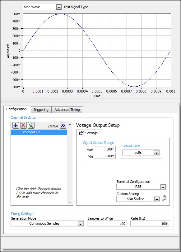
I have an usb-6341 or data acquisition. in our project, I want to generate 1 kHz sine waves go AO0 and inject our test module and the output
I want to measure the output signal of AI1.
in the NI MAX tasks Panel, I made this settings
If I understand correctly to produce the output signal of 1 kHz I put samples to write = 100 and a frequency of 100K?
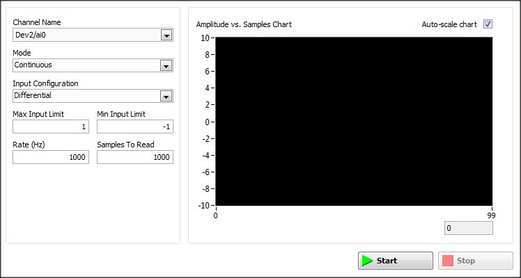
But what settings I need to set in the window of analog input
Thanks for a response
Hi Arbo,
the configuration depends on what type of signal you would expect.
If it will be similar (frequency & amplitude) that generated, then configure the same as AI. One thing you should pay attention to, is to choose an appropriate Terminal configuration (Diff, CSR, NRSE) - you can read about it here: http://www.ni.com/white-paper/3394/en/#toc4


Maybe you are looking for
-
I'm under NT-Newswatcher on my 10.8.5 than MacBook Pro for Usenet and it will no longer work with the newer operating system. I like NT - W because I'm going out ITI brands all groups of discussion, a reading and then erased them or whatever he does
-
Help! Large iTunes library split into two locations, how to fix?
Long ago, I told iTunes to store its iTunes Media on a NAS file and I copied the iTunes folder all my D: to the NAS unit. I also said iTunes to keep organized records and copy files of music added to the NAS. I just found out by examining the XML fi
-
Startup gets "Network cable unplugged" on (new) wireless mini-PCI card
Repost in the previous topic was locked, but has not been resolved. Original post below, please see previous post for more details I recently installed a Netgear DG834GT wireless router and now have intermittent problems connecting my Tecra 9100. If
-
How long works has battery Satellite A210-16Fon?
Hello Anyone have experiences with satellite A210-16f?How long does it work on battery? I again a210 16f (1 week) with win Vista and I can use only 1h30min.Is this right? Post edited by: George26
-
My windows activate wont show up!
I try to activate windows... but all I get is this http://img24.imageshack.us/img24/6218/updatevb.jpg can someone tell me please on what to do? Thank you very much Brendan