PCI, I / AO at a different frequency
Hello
As a newbie, I met a problem when I tried at the entrance and the analog output signal at a different frequency.
I followed PID-control - Multichannel .vi to build a control program, so input/output can be synchronized. However, the project requires that the frequency of I be tenfold of the AO. I could re-write the while loop to make the output value constant for 9 of 10 cycles. However, in my view, it is simplest way to do.
Anyone provide an example?
Thank you in advance.
Sincerely yours
Ming
lmuri wrote:
Hello
As a newbie, I met a problem when I tried at the entrance and the analog output signal at a different frequency.
I followed PID-control - Multichannel .vi to build a control program, so input/output can be synchronized. However, the project requires that the frequency of I be tenfold of the AO. I could re-write the while loop to make the output value constant for 9 of 10 cycles. However, in my view, it is simplest way to do.
Anyone provide an example?
Thank you in advance.
Sincerely yours
Ming
Hello Ming!
Please use the Forums of NOR. You'll be happy to know DAQmx allows what I/O tasks such as these to be not run not only at the same time, but at different rates.
The problem with the solution that you have imagined is that this implementation will remove the delegation of tasks to the hardware level, and your program would become software-driven; This becomes a problem when you perform tasks of acquiring data at very high speeds as it becomes limited to the speed of your operating system (OS).
You can coordinate your tasks to operate synchronously and perform the output and the acquisition at different rates by creating a maintask. This means generally that you configure a task by DAQmx that keeps a clock frequency and you create tasks that use this clock frequency, or a division thereof, to exploit to their own individual frequency. This facilitated not only the execution of DAQmx tasks synchronous but also provide a material entirely focused on the solution of performance maximimse.
Thanks to LabVIEW, if you go to help > examples find to open the Finder of example of OR. If you are browsing material input and output > DAQmx > synchronization > multifunction > Multi - multifunction - Synch Dig read write with Counter.vi, you will find an example of how to set up a counter as a master of the task to control the operation of operation both a reading and writing . (This example shows a digital but implementation may be easily replaced by analog).
By setting the meter to the maximum frequency rate that you will require for your task (in this case, the speed at which you want to copy values) and apply it to the output of the SampleClocktask, you will drive the clock output task with the counter as the clock source. You can then use the meter as the source of the SampleClock for the task of entry, however to set the rate at any division of the driving frequency. In the case of your example, you can set the bit rate to 0.1 times the frequency counter to acquire a 10th of the rate.
If you want to acquire at the same rate, but only to retrieve values on the 10th of the speed, this same solution can be configured to produce instead a trigger to return an acquisition in the buffer. With a master synchronizing the task, the possibilities are endless!
I hope you find it useful, and if you need a precision more do not hesitate to let me know. Have fun with your DAQ!
Tags: NI Software
Similar Questions
-
I use the outgoing/incoming analog DDK with the DAQ 6341 SMU map.
The examples, for example aoex5, show a single timer (method outTimerHelper::loadUI), but the example shows the DMA loaded with same size of vector data.
There is a comment in the outTimerHelper:
 call rogramUpdateCount, which implies that memory sizes different pad per channel can be used.
(the comment is: switching between the sizes of the various buffers is not used)
Nobody knows what should be the format the DMA buffer for data from multiple channels with different frequencies?
For example, we want a0 with a sinusoid at 1 kHz and a1 with a sine wave of 1.5 Khz. What looks like the DMA buffer?
With the same frequency for each channel, the data are interleaved, for example (ao0 #0, ao1 #0; ao0 ao1 #1, #1,...), but when the frequencies for each channel is different, what the stamp looks like?
Hello Kenstern,
Data are always intertwined since each card has only a single timing for each subsystem engine.
To AO, you must specify the number of samples that will be released to the AO. You also specify the number of channels. Because he didn't is that a single engine timing for AO, each AO will be channel will be updated at the same time to update clock tick. Data will be interlaced exactly as shown in the example because each channel AO needs output at each tick of the clock to update. The data itself can change depending on the frequency you want to copy.
kenstern wrote:
For example, we want a0 with a sinusoid at 1 kHz and a1 with a sine wave of 1.5 Khz. What looks like the DMA buffer?
With the same frequency for each channel, the data are interleaved, for example (ao0 #0, ao1 #0; ao0 ao1 #1, #1,...), but when the frequencies for each channel is different, what the stamp looks like?
In your example, you must come with an update rate that works for the two waveforms (sine waves of 1 and 1.5 KHz). To get a good representation of a sine wave, you need to update more than 10 x faster than your fastest frequency... I would recommend x 100 if possible.
Update frequency: 150 KHz
Channels: 2
Then create you stamps that include complete cycles of each wave you want to produce based on the frequency of update. These buffers must also be of the same size.
Buffer 1: Contains data for the sine wave of 1 KHz, 300 points 2 cycles of sine wave
Buffer 2: Contains data for the sine wave of 1.5 KHz, 300 points, 3 cycles of sine wave
You can Interleave them as before. When the data are performed through the ADC, they are out different sine waves, even if the AO channels are updated at the same speed.
-
Same result for different frequencies?
Hi all
I'm new to labview and the communication kit, so I'm trying to test the examples.
When the example of 'Rx Continuous Sync or Async' opening and it works I get the same output on the "power spectrum".
i'm checking different frequencies in the range of 1.2 GHz to 6 GHz.How is it possible then that there is nothing transmitted? -> checking with the android application for wifi channels (channels 1 to 8 are used, all others are not...) and yet labview gives me the same result... (attached file = 2 GHz, the other is a comparison of the 5 GHz, 2,412 GHz and 2,484 GHz)
material:
NEITHER USRP N210 (rev 4)
CBX 1200-6000 MHz Rx/Tx (40 MHz)
Antenna VERT900connecting via gigabit
PC: W7 64 bit, i7-2600 to 3.4 GHz, 4 GB RAM
Thanks in advance
Hey insiderbe,
I did some research on the Ettus forum and found the following:
https://lists.gnu.org/archive/HTML/discuss-gnuradio/2010-08/msg00237.html
https://www.Ruby-Forum.com/topic/214890I suspect that the IPS you see on 0Hz is the DC offset that is introduced to the ADC of the USRP N210. We can confirm this by removing air and closing the RX. If the tip is still there, it's a feature of the analog input circuit.
Brian of Ettus recommends tuning your frequency slightly out of your signal of interest and using a high pass filter to remove DC offset. I recommend looking at the second link for more information.
With respect to obtaining the value of art through many different frequencies, I think that it is a property of the antenna used. The VERT900 is valid from 824-960 MHz and 1710-1990 MHz. can you listen to one of these groups and test your power, even if you have a known signal? You have another USRP generator or a function to generate a known signal?
https://www.ettus.com/product/details/VERT900
My last concern use the N210 with the CBX in LabVIEW Communications. According to the Readme, it's an unsupported hardware configuration, which means that R & D has not tested the configuration, and we do not know how the configuration will occur.
http://download.NI.com/support/softlib//RF/NI%20USRP/15.0/niUSRP_readme.html
Thank you for this post!
Kind regards
-
Generating analog output signals 4 with different frequencies
Hi all
I was trying to say to generate 4 different signals at different frequencies
1. first waveform is a sine wave with 5000 Hz,
2. other with 8000Hz,
3. third, one is a square with 25 Hz waveform and
4. fourth one with triangular waveform 50 Hz
all waveforms must be generated simultanoeusly.
I tried to generate with the task unique analog output and sample clock (clock rate is 100000). Cross in scope that I see only 5000 and 8000 Hz we generated correctly and the rest two waveforms show the incorrect frequency.
I guess that's due to the frequency of high clock to sample for more low frequencies for ex 25 Hz and 50 Hz. If I reduce the clock rate to get the lower frequencies properly so I can't generate frequencies higher correctly. (there's a clsh between frequencies and the clock frequency)
Is it possible to use DAQ board master sample clock and its magnitude downward revision (everywhere where it is necessary for each waveform separately) to generate all the signals at different frequencies at the same time in a single task?
-
Hello
I'm working on a project that requires two outputs digital signals at different frequencies. Frequency of the phase 1 is about 1 kHz and is modulated on and off to a pace that will change during the execution of the program. Wave 2 passes from 1 kHz to about 6 kHz while needing to be pretty accurate to the tenth of a Hertz.
Initially, I tried to manage the simultaneous output of signals at different frequencies using a single task on a single 9477 daqmx in a cdaq-9174 chassis. As far as I know, the best way to get a specific frequency in a waveform output is to set the sampling frequency up to 2 times the frequency of the wave that is generated and generate a waveform that is given to each clock cycle. This works very well when it comes to a gesture, but I was unable to get the frequency of the modulated wave (wave 1) remains constant when the frequency of wave 2 modified or vice versa.
I have a few other modules lying around (another 9477, 9403 and 9476) and I thought I would try another task running on a separate module. I find myself receive error-50103 message if I add these modules to my cdaq chassis and run one of the waveforms of a task set to run on the add-on. Is there a way to bypass this error? I guess it would cause by running two digital output on the cdaq-9174 tasks at the same time, but it seems to me that this wouldn't be a problem with an additional module.
How can I have two outputs digital signals, running at the same time, maintaining their independent frequency frequency of the clock of the other sampling rate changes. In addition, because the wave 1 is enabled and disabled at a defined frequency, I use it to set the number of samples to write when you write a range of waveforms in the module (when generating these two waveforms on the same module).
I'm sorry if the explanation was difficult to understand. I've attached an example of error 50103 lifting. This isn't really a part of my project as a whole, but it is the easiest way to reproduce the error.
Thank you
Hi awol.
I have a follow up for you. You encounter the error because the cDAQ chassis has only a timing engine of. You will not be able to perform simultaneous tasks of the call by the hardware. Please see the following knowledge base: http://digital.ni.com/public.nsf/allkb/5E0B829E50ADE1BC86257AC50062B2D2
Mike
-
Several channels with different frequencies
Hello
I use card NI USB-6221.
The C API using, I need to generate 6 digital output channels, with frequencies of diffrenet and Heavy duty.
To be more precise, the 2 are totally identical, but I need them to be reversed, and the other 4 are similar to another, but should be shifted in time (I.e. There is a delay between each of the channels).
I used the 2 channels of CO that the USB-6221 takes charge for the first two signals, and it works very well (the two signals are synchronized and are reversed).
Now I need an additional 4 channels for the other vague square.
I saw an articale NOR by JohnP web site with the title:
Generate multiple channels of digital output with different frequencies and Heavy Duty
The following example shows how to create and generate a digital with the non-regeneration wave form so that you can change the frequency and the duty cycle on the fly with the M Series DAQ hardware X. The example uses output digital rather than counters to achieve this, so if you need more output than the available counters, it would be a good option (Note: on the materials of the M series an external sample clock must be provided, this may be caused by one of the counters if you want).
that seems to be exactly what I need, but the examples are for LabView which I did not.
Can someone explain how to do this with the C functions?
Best regards
Danny.
Hey Danny,
The important thing to note is that you can clock of arbitrary digital waveform (up to 1 MHz on the 6221). The real data acquisition programming is pretty easy once you have the waveform. My Example LV used LabVIEW Base generating function VIand then converted to a digital waveform to generate the signal from each channel.
The functions of LV helped tremendously with to achieve the waveforms to be updated on the fly (the basic function generator keeps track of phase for you).
If you do not need to be updated on the fly, then the construction of the waveform in C should not be too bad. For example:
P0.0 [1 1 1 1 1 1 1 1 1 1 0 0 0 0 0 0 0 0 0 0] * 1
P0.1 [0 0 0 0 0 0 1 1 1 1 1 1 1 1 1 1 0 0 0 0] * 2
P0.2 [0 0 0 0 0 0 0 0 0 0 1 1 1 1 1 1 1 1 1 1] * 4
P0.3 [1 1 1 1 1 0 0 0 0 0 0 0 0 0 0 1 1 1 1 1] * 8
[9 9 9 9 9 3 3 3 3 3 6 6 6 6 6 12 12 12 12 12]
The table above U8 would give you 4 output waveform of 50% duty cycle at Fs/20, shifted 90 degrees to eachother. The lines would be p0.0 by p0.3 (the bit rate of the U8 corresponds to what line goes high).
Best regards
-
Generate 2 Trains of pulses with different frequencies and Heavy duty with a PCI-MIO-16XE-10
Hello
I use a Board PEAK-MIO-16XE-10 DAQmx with LabView 8.6 to run a door for a piece of equipment controller. I need to create 2 separate, all pulse trains both trigger simultaneously, each with their own cycle frequency and duty. So far, I can create 1 pulse train and it works exactly as I need, however, whenever I try to enable the second train (called a door in this VI), I get an error saying: "the specified resourse is resevered," even though the first door is configured to use counter 1 and the second must be set to use counter 0. As I understand it, this map contains 2 separate counter/timer modules, so this should be possible. A large part of the rest seen in the attached VI's preparation for the signal processing and other controls that I use that I finished this VI.
Thank you
<><>
Hi Eric - you forgot to attach your VI. I did what you're trying to do with a similar card, but who has been using NOR-traditional DAQ (before DAQmx). It should be possible with DAQmx as well. A quick search on the forums turns up these two links, which suggests that your problem is that you try to create two tasks separate DAQmx, one for each counter. What you need to do is create a single task DAQmx which includes the two counters, then together, that their frequency and duty cycle regardless.
http://forums.NI.com/NI/board/message?board.ID=170&message.ID=241602
-
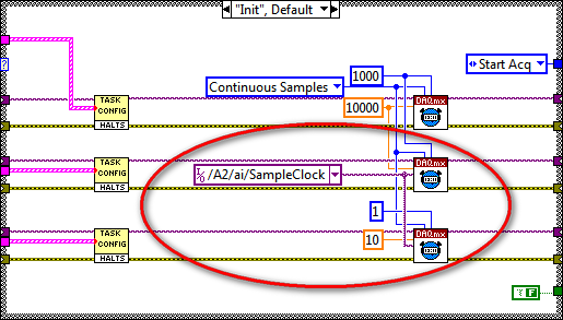
Synchronization of several high at different frequencies of sampling DAQ cards.
I'm having sync problems 3 high DAQ cards with different sampling frequencies. I use 2 cards PXI-6259 nec 10,000s samples and 1 PXI-6221 Board to interface for my SCXI modules in 10 samples/second. The problem that I discovered is the time related with the waveforms of the NI PXI-6221. When I run the code on a development computer using virtual devices in MAX, it works as expected. When I run the same code on real hardware, the stopwatch turns approximately 25 X faster than normal. I enclose the code and the config that I use.
Any ideas?
Hi NGNN CAD.
First of all, let me say that your code is very nice!
The problem is that you are using the fast sample for the device that is supposed to be slow clock:
Even if you specify the rate as 10 Hz, the clock itself is still at 10 kHz (by specifying the right rate allows the DAQmx driver determine the size of buffer etc and don't actually change your external sample clock speed - however, it changes the rate of the simulated device).
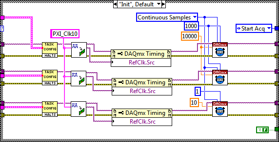
My recommendation to synchronize devices would use the built-in PLL and lock to the reference clock 10 MHz of your PXI chassis. Your devices would always share a trigger to start, but each would generate its own sample clock based on its time base that is locked to 10 MHz reference.
The code should look like this:
I hope this helps, let me know if you have any questions!
Best regards
-
Different frequencies of signalexpress with oscilloscope
Hello
I'm new to the signal processing. I am facing some difficulties to measure the signal of a sensor of acoustic emission for my project. I use the PXI-6115 module with 1042 q and terminal block is TB2708. I used AI0 and AI1 for main signal and trigger respectively. I acquired the signal of 6115 in SignalExpress (v3.0) and convert to linear spectrum (Hanning window) and conversion of RMS with RMS on average 200. Same parameters are used in the oscilloscope (LeCroy LC564DL) too. I plugged the two signals of oscilloscope as well as for comparison. I saved data from the spectrum of SignalExpress and oscilloscope and plotted. You can see the graph as an attachment. It's totally different. Why is it so?
And one more thing, that is if I disconnect my connector NI DAQ system, spectrum in oscilloscope changed in amplitude at a certain frequency and vice versa.
Thank you in advance.
Myo
My apologies for the late reply. I've been sick for a few days.
I generated an amplitude 1V (2V peak-to-peak), 100 kHz, 10MS/s 20ksample sine wave to help to create an analog Signal. I treated it with the power spectrum using 200 linear medium with RMS algorithm. Value at 100 kHz - 3dB, as expected and as it should.
However, at a given time in the process, forced SignalExpress my frequency of 100 kHz to 50 kHz (probably due to a shift of frequency and the number of points). This would result in what you see. Check your project to see if this has happened to you. If so, you would get - 350dB to 100 kHz (essentially a pure signal noise floor) and - 3 dB to 50 kHz.
-
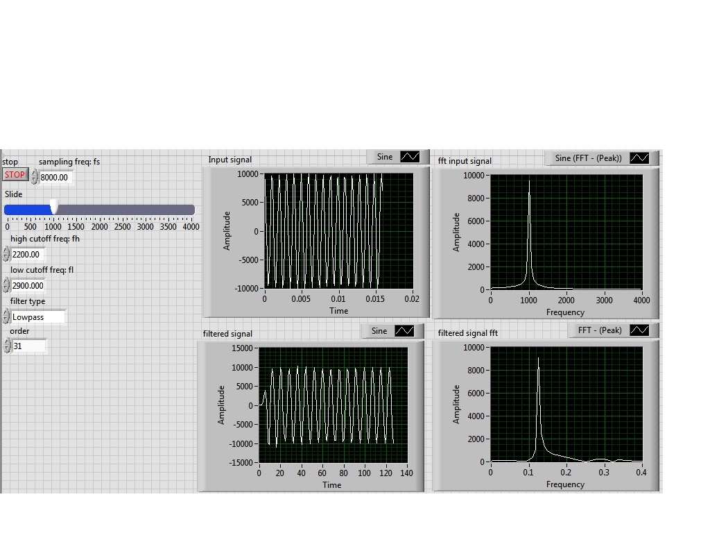
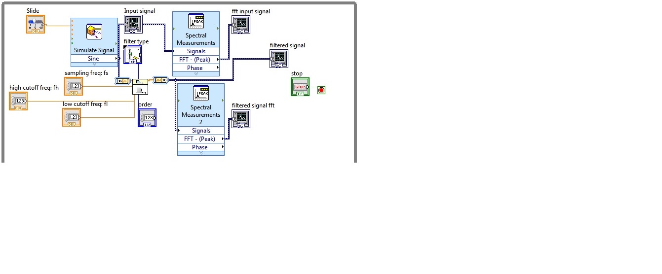
I'm simulating a sine wave at approximately 1000 Hz (I'm variable according to the frequency with a slider), I would like to pass this signal by a lowpass filter (butterworth) with a high frequency of 2200 Hz cuttoff and a low pass to 2900 Hz frequency. However, the output after the filter frequency seems to be lower in the order of a thousand. the output frequency is about 0.1 Hz.
Y at - it someone who can guide me please to solve this problem, I tried different filters and I'm still having this problem, it would be incorrect sampling?
I enclose the block diagram and the front panel
Because you use express screws and the type of dynamic data...
You convert the signal of DDT (which contains the clock information) in a table DBL to perform filtering. Take it a DBL array (which contains no data of timing) and converted it into a DDT (which now contains no data timing). That's why when you try to view and analyze it you have lost all the data timing (frequency).
If you were to exit table DBL of your filter and build a wave form and provide the dt to the waveform of the sampling frequency control, then it will work.
Better yet, ditch the DDT and use waveforms from the beginning

-
Measure the resistance with PXI DMM 4072 on different frequencies
Hi all
I tried to get on board various and unable to find solutions for that. I'm trying to measure resistance using NI PXI-4072 on frequencey 1 kHz, but not luck. When I try to use Agilent LCR meter I see the correct value of the resistance.
I've seen a few posts on this but don't have no satisfactory solutions.
In above post, someone said that I can use 4072 DMM OR digitizer, does not have a lot.
Can someone please provide the right path for me to solve this problem.
Thank you
Hello Puneet_K,
I checked the data sheet and the method of measurement described in the specifications of the NI 4070/4072 http://www.ni.com/pdf/manuals/371304g.pdf; indicates that the ability is measured using an alternating signal and select the test frequency range, for example 3 kHz, 1kH or 91 Hz. The resistance is simply measured using a DC signal, and it is often sufficient to measure the internal resistance of a battery. If you need a more flexible control for the measurement, you probably get a card like the function generator and then set a multimeter to measure the voltage and another DMM to measure the current and calculate the impedance of these values.
I hope this helps!
Kind regards
-Natalia
-
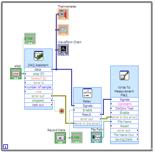
Hello I'm trying to read in a temperature of a thermocouple and displayed on a waveform graph and at the same time, I want to write data to a file at a significantly lower frequency. Currently, I am sampling data acquisition at chaque.01s and I would like a sample to write to the file every 2 s. I thought of activating/deactivating the option activate the relay every 2 s, but I don't know how to do that and I wouldn't be surprised if there is a standard way to do this, but I've not been able to find.
Thank you
Miguel
If you are sampling of chaque.01s and you want to write a snack every 2 s, what about all the other samples? You want to just throw away? You read so 200 samples in 2 seconds. But you want to write a sample. You can do it if you don't mind losing the other 199 samples.
You could use the elapsed timer function and the release of the elapsed time of a structure of business wire. Put your writing inside the real deal function. Nothing in the case of false. Make sure that all of the timer to reset automatically. If every two seconds, the case will be set to true, and will be called the write function.
-
How to synchronize two ports data series at different frequencies of sampling?
I have a .vi I'm reading two different sensors that operate at different sampling rates high. I am able to read these two, however, there seems to be some problems of synchronization/strange offset with the devices. The first device is a device running at 5 Hz GPS. This is convenient because the time GPS is included in the data that I read. The other device is a sensor operating at 6 Hz. Ideally, I am recording the data of these two devices in the same file. An example is attached. It seems he collects GPS data, although it seems to write at much lower rates. Strangely, as it is written to the file, it will slowly store 'blocks' of data in order to a much lower rate. It seems that a lot of the GET of a buffer, and then it jumps ahead by about 5 seconds (see lines 214-220 of the attached file). Meanwhile, the data from the sensor 6 Hz are get recorded normally. I'm puzzled. Would it not be better to connect these as separate sets of data in separate files? Creating two executions of read/write "parallel" within the same .vi?
Any help or examples, would be much appreciated!
-
Write to a file at a different frequency?
Hello:
I want to represent a two variable of each 200 m graphic waveform is what I do in the attached vi. But I also want to write on a file of this measure two variables variable rate (user can change). Where and how can I put my 'Write to file measure?
Please, see the attached vi.
Hi damos,.
"With the structure of the case, I don't know what to do with the output on the case of false tunnel.
In this case I suggest to go through examples provided with LabVIEW or to read the course LabVIEWBasics on the website of OR...

-
Time to update buffer PCI-6713
Hello guys,.
We use PCI-6317for 50 Hz generation of waveform of 3 phases for a quite a while using the library OR-DAQ traditional.
We could not get a reliable update of a waveform with a single call to the WFM_DB_Transfer function and need to call double.
Otherwise, we could sometimes get a signal consisting of the buffer past and present.For now, that's a good solution, but now we have different requirements.
We went to NOR-DAQmx and surprisingly managed to update the PCI-6713 buffer with a single call to DAQmxWriteAnalogF64. But it seems that we can update the buffer only once per period of output signal.
For our 50 Hz signal is 20mS. Function until the next blocks.That is the first question.
Can we call DAQmxWriteAnalogF64 wave update more often than 50 times per second for the output 50 Hz signal?If the answer is positive, how can it be done?
I have attached a LabWindows CVI 7.0 source code for an example of test (for 1 channel only) program we wrote specifically for this post.
The waveform generation is started by calling ConfigureTask and StartTask reminders in this list.Could someone kindly tell me what changes to the code have to do to update the asynchronous output with output buffer?
And another question.
PCI6317 can generate signals with different frequencies (channel 1 said generates 50 Hz signal, channel 2-60 Hz, etc.)?Thank you very much for all supplied glue!
Andriy
The answer to this question is no. It is not possible to dynamically change the environment buffer output. You must wait until the buffer is exhausted, and then change the stamp on the next set of data.
The only thing to do with your current hardware is to reduce the size of form of wave/buffer. You must call the function write significantly more often, but you can change it to any of these points.
Also, get a reliable 3ms response in your software feedback loop will be entirely dependent on the speed of your computer. If Windows decides it must allocate resources elsewhere (automatic update check, MS Word being opened, Media Player, play music), then the program CVI can certainly lag. That's why he could miss the update of buffer, which is probably the reason why you get the error 200290. The code cannot run fast enough for all process before the depleats buffer.
The absolute best thing to use to control is one of the FPGA modules. With them integrate you actually in the material you want your control algorithm to be. This means that the control algorithm is all timed material, producing the best possible response times.
What rate are you inputing to the sampling frequency? In addition, in the code you sent that you send "fFrequency * SAMPS_PER_GRID_CHANNEL" to the DAQmxCfgClkTiming function. I wonder why you're multiplying your frequency of SAMPS_PER_GRID_CHANNEL. The rate input parameter must be just the frequency in Hz you want items to be generated at.

Maybe you are looking for
-
I was wondering if I should get an iphone 6 or 7? What is the difference?
-
Satellite A60-106: ATI graphics card driver update
I have a laptop Satellite A60-106 and I was told to update my driver graphics ATI Mobility Radeon 7000 IGP, otherwise I won't be able to view the photos taken from the video. I'm unable to locate these updates on the Toshiba site. Nobody knows where
-
labview probe button is missing in Schema view?
no idea why the labview probe & I miss a Vi diagram display?
-
indication of memory consumption
How we see the physical memory consumed by the code that is running on windows? Is there a way to see the performance of the processor by using the windows Task Manager, but what about memory?
-
VISA of TDS2002B scope control
We use Fluke METCAL for calibration. Using Windows XP Pro (updated SPs) I was able to set up and use a USB based TEK TDS1002 (A) O-Scope with VISA after update of the VISA of NOR-MAX portion. Now, I received a litter of TDS2002B TEK, but when I have