frequency DAQ USB issue (6211)
Hello
I'm a newbie when it comes to NOR and data acquisition. I bought a NI USB 6211 and connected a resolver with 400 Hz and ai1, ai2 (CSR) (sine and cosine signals). I also have the reference of the power supply connected to ai3 (differential) of signals. Pockets of tension give a +/-2.5 Volts from all sources input signal.
The problem is that the signal moves to the right. She moves uniformly for all signals.
Now, I wonder is it possible to synchronize the input signal so that it moves? or what I need to resolve this issue programmatically? I'm programming in C with standard DAQmx drivers (v15.1). But I saw the same problem with Labview and Measurement Studio.
Thanks in advance for your suggestions.
Kind regards
Gerhard
I guess I just find the answer to my question here:
http://forums.NI.com/T5/LabVIEW/DAQ-Assistant-can-t-lock-the-signals/m-p/1332484#M542285
I guess I have to ask in the forum section of C++ for an example of a software lock.
Kind regards
Gerhard
Tags: NI Hardware
Similar Questions
-
What is read maximum speed of 6343 DAQ USB
Hi all
We have new application of 6343.Its USB DAQ note (or say different) says he's sampling frequency is 500 K samples/second. Now I need some clarification from you guys. I have to read digital data (series or parallel). so please tell me how far I can go with this product for both feeling.
Thanks in advance,
Although not for the 6343, here is a post that can maybe help on the X - series cards
-
DAQ USB 6363 - generate digital data series through the single DIO line
Hello
I'm new with Labview, currently, I bought NI DAQ USB 6363 for generating control signals and signals analog accquire. I would like to send digital data series through one of the digital IOs with throughput of 30 kbps. Please see the attachment for the data frame. Could someone comment the feasibility of this? Y at - it codes for the example that I can refer to? Most of the examples I've looked at so far deals to generate several line instead of 1 single line. How can I achieve this?
Thank you
Diem
Hey diem.
After looking on your code, I understand what you were trying to do. Here's how I'd do. Usually we do not write code to clients, but you peaked my curiosity of! I hope this helps. Good luck!
~ kgarrett
-
Acquiring bipolar signals NI DAQ USB 6009
Hello
The NI DAQ USB 6009 case is capable of acquiring biploar waveform? I have a signal generator that provides a 0.5V wave triangular amplitude in the NI DAQ USB 6009. The NOR-DAQ is connected to LABView and acquire signals using the LabVIEW express vi. The waveform that appears is unipolar. Terminal configuration is set to differential. Is the waveform which is seen. Thank you. Mary
Hi Tupaj,
See a voltage floating as this can sometimes be the result of a measure badly grounded. It would be useful, like Dennis, to know how you have this wired up. Please take a look at this guide to make sure that the device is properly connected to Earth:
Field wiring and analog noise - http://www.ni.com/white-paper/3344/en
In addition, information about the configuration of your software are also important. Here's an example of how implementing a fundamental mission of analog input for your 6009:
Video installation instructions - http://www.ni.com/swf/devzone/ai/
The example Finder has also several screws that already do it for you. If you work in 2012 before LabVIEW, look for Acq Cont & chart voltage-Int of the Clk.vi in the Finder of the example. LabVIEW 2012 will have a similar named VI voltage - Software-Timed Input.vi.
Kind regards
-
Hello everyone...
IAM going to use it NI DAQ USB 6008 Board so to do this I have been programmed and build later... I would like to install in another computer for all this help drivers must tΘlΘcharger or?
Thank you
Only drivers of data acquisition is enough to install NI DAQ USB 6008.
-
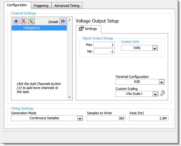
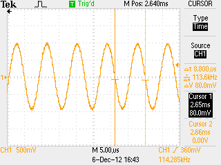
I use a box NI USB-6251 and frequency max I can carry out to an0 an1 is 8 kHz using the following parameters. Is there a way to reach a frequency higher on the analog output ports?
Config:
Capture of the oscilloscope:
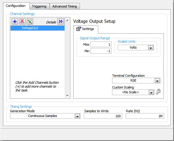
I've reconfigured the config to try and hit 10 kHz and captured the following response.
config:
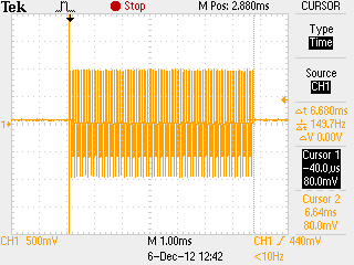
Oscilloscope Capture: (before port analog flat doubled)
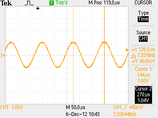
The signal is emitted for 7ms then faints.
Any ideas how to set up the analog interface for a sine wave of 100 kHz to the stable address? I could only create a stable 8 kHz wave.
To use higher frequencies, you'll need to use LabVIEW or custom code. I used the example of "ContGen - IntClk.c" located in "C:\Users\Public\Documents\National Instruments\NI - DAQ\Examples\DAQmx C\Analog Out\Generate Voltage\Cont Gen Volt Wfm - Int Clk ANSI" and changed the two lines of code to achieve higher frequencies.
2 changed lines:
 1. data[i]=1*sin((double)i*2.0*PI/25.0);

 2. DAQmxErrChk (DAQmxCfgSampClkTiming(taskHandle,"",2800000.0,DAQmx_Val_Rising,DAQmx_Val_ContSamps,1000));
Output waveform:
Thank you TO help me with this. =)
-
AO. MaxRate, AO. MinRate, AO. Properties of voltage. RNGs for hardware DAQ USB-6008
Hello
in one of my report, I use the AO. Property of Voltage.Rngs to see if the selected DAQ card takes in charge the application voltage range. This works very well for my PCMCIA card as well as a PCI card. Now run the same VI with a USB-6008 device, this property gives all the return values. In addition, the report of AO.max.rate and AO.min.rate of the '0', the output is-200197 error properties. I use DAQmx as it is supposed to support the same functions for all DAQmx devices. Can someone please tell me what wrong here and how can I get around this?
Best regards
Gabs
AO.min.rate and AO.max.rate are 0 and error-200197 back because the USB-6008 case supports the outputs analog hardware timed. The description of error is "device does not support this property." There is an entrance to the knowledge base for this question.
By selecting 'Use Waveform' uses the synchronization of the sample clock. The waveform data type specifies a delta t, which is used to set the sample clock frequency. It is not supported on the box USB-6008. You shouldn't set your calendar of sample type or explicitly assign the "On Demand".
The DAQmx driver supports hundreds of different devices. Not all combinations of properties are valid for all devices.
-
precision of typical Voltimeter DAQ USB-6009
Features: I wonder what are the features of the USB DAQ 6009 regarding:
-Stability and accuracy, + /-(reading ppm + ppm of range) and the resolution of analog inputThank you
And you never thought to go to the products page and find links to the manuals or even the Support page?
-
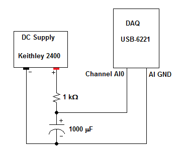
Test capacitor does not load when DAQ USB-6221 is used as a measuring device
Forum of NOR expensive, I have a Setup (see below) which is supposed to read the tension between a capacitor and a resistor in series. Unfortunately, I found that the capacitor is unable to load completely with the connected acquisition of data entry. However, if I remove AI0 connection of the circuit and the capacitor charges normally...
I would be grateful if someone could explain to me:
- Why this happens
- If there is a way to change my test circuit in order to fully load the DAQ capacitor is connected
For reference, I tried to change the position of resistance and capacitor (i.e. initially the capacitor in series), and in this case, the capacitor had no problem charging. But for my purposes, I will need to test with first series resistance because I already have a lot of maps of test which are built this way.
The food is set up to provide 75V (the rated voltage of the capacitor) when put on and the current limit is set at 20 Ma. With these settings my capacitor only charge about 20 or 30 V with DAQ in the circuit.
Let me know if I can give more details and thanks in advance to those who give thought to my question,
You may test the limits of your USB-6221 surge. I hope that you don't him don't have not damaged.
You should be able to use some simple resistive voltage dividers for tensions in the acceptable range. They will limit your ability to measure the leakage current.
Lynn
-
BSOD when base closing program NI DAQ USB-6009
So, as the title suggests, I get the BSOD error code: MULTIPLE_IRP_COMPLETE_REQUESTS when I close the basic example of the analog input for NI USB-6009. Someone at - he lived this before? My specs are:
-LV version 15.0 32 bits (developing 64-bit installation to solve a problem without a report, do not know if this will help here as well)
-Win7 Ultimate x 64 (SP1)
-Alienware M17x R3
-Core i7-2860QM
-12 GB OF DDR3 RAM
Any ideas on what could be the cause?
Does happen with particular vi or exe or anyone, including max and daq assistant? If it was built on this machine? Try to force recompile all (Ctrl + Shift + click the button run.
I can hardly imagine what can be encoded in simple artificial intelligence causes of BSOD. I'd say it's machine problem. Something is not installed correctly. Is - this change help USB? Card mother does a USB 2.0?
-
DAQ USB-6008 will be able to power and record voltage for UMS T5 blood pressure at the same time?
I would use my NI USB-6008 to power my blood pressure monitor UMS T5 (http://www.ums-muc.de/en/products/tensiometer/t5.html) but also to take readings of it, but I don't know if it's possible to do it properly. The power supply for the instrument can be as low as 5V, I can easily get the dedicated + 5V channel. I'm able to feed the instrument and connect it to an analog input on the 6008 and measure a voltage in differential mode. However, when you read the documentation of support for the instrument, I find the following:
"Potential pitfalls of data acquisition: the pressure transducer is configured in a full Wheatstone bridge, the input voltage and mV signal output can be connected to the same reference (mass)." Therefore, the mV output signal can be measured using a differential voltage measurement. Therefore, do not make an asymmetric measure of pressure transducer mV output. "(http://www.decagon.com/assets/Uploads/MeasuringUMSTensiometerswithnon-UMSControlandDataAcquisitionSystems.pdf)
My understanding is that the 6008 can take a differential measure if I attach the signal '+' and the signal "-" to the analog inputs of positive and negative terminals. However, it seems that all the ports of ground on the 6008 are grounded to the same reference, which would make my measure of invalid tension according to the above paragraph. So my real question is: if I try to record the voltage with one of the analog inputs on the 6008 in this way, is the valid measurement? Or I need to find a separate power supply, with a different reference field to ensure that the measure is accurate?
The technical details of this device is very poor. The manual is not much better. Companies that want to sell scientific equipment should publish decent cards or get out of business.
In section 3.4.3 General requirements the device is described as a "bridge not amplified circuit. This information along with the impedance of the bridge should be in the specifications, because it is essential to apply the device under any circumstances other than the nominal behavior in 10.6 V.
The answer to your question is:
You can use it with the box USB-6008. The 5 V supply will result in output voltages a little less than half (5/10.6) the voltage specified in nominal conditions. You can use the differential input mode on the box USB-6008. The absolute input voltages will be approximately 2.5 V with the 5 V power supply. This voltage is in the range of the aircraft. The differences are likely to be less than 100 mV. The resolution of the USB-6008 on the + /-1 V is located about 0.5 mV so your resolution of pressure will be about 1% of full scale. The voltage input impedance and termination of the USB-6008 will present a few errors. These can be in the order of 5 to 10%. I can't predict much better without the missing bridge impedance specification. These errors should be relatively constant and systematic. A calibration of the whole system - sensor and together hardware DAQ should allow you to compensate for a large part of this error.
Lynn
-
Using the DAQ USB-6009 meter and an analog input voltage at the same time.
Hello
Currently, I'm reading the two channels of voltage with the USB-6009. It happens that one of the channels is the output of a digital coder, and it would be much easier to use it directly to the PFIO entry that is defined as a counter. The problem I am facing right now, it's that I can't use the DAQ Assistant to use the analog voltage to a channel and the digital channel counter at the same time. Once I put the DAQ Assistant to read the input from analogue voltage, I won't be able to add analog inputs. And as I put the DAQ Assistant to use the PFIO as a counter, I can add more entries to read analog voltage is.
I wonder if it is possible to solve this problem using the lower level data blocks? Another solution would be to read two channels in analog input voltage and that the use of Matlab to process data resulting from it, since I was not able to do the counting to work simultaneously with the acquisition in Labview to impulses.
Hope you guys can help out me.
Thanks in advance.
Using a simple wizard of DAQ is incorrect. You need one to acquire analog inputs and one for the meter.
-
To write a waveform to two outputs analog of DAQ(USB-6215)
Hello
I use USB-6215, who has two analog outputs and having to send the same waveform through the analog outputs two of my DAQ. at the same time. in fact, I have a text file consisting of a code word (please see the attatchment) with dt, freq and annex 0 in the first column and other columns contain the word coded. Withe the help of dt, the rate and the data I did a waveform with the wave of construction VI. I am able to write this wavefrom through an analog output A01 right now. I want to know how I could write the same analog waveform other AO0 out simultaneously. I use a source of external triggering via PFI0 to be triggered. for now, I use the write.vi DAQmx (analog channel 1 DBL 1 d N samples) and DAQmx create virtual channel.vi with dev1/ao1 as the physical channel. For more information, I am attatching the program along with the text file. Please see page 2 of my structure of matter in the VI attatched.
Thank you.
Kind regards
Raja
Hi Steve,.
his works now. I changed the instance of writing DAQmx for analog waveform samples N channel N. still, I now that a single waveform. How could I do like two like it (writing DAQmx) will not accept a single waveform as the entry as the number of channels in the task will now be 2 where, under the waveform has an exit.
Kind regards
Raja
-
I have the cable connected to the USB 3.0 motherboard USB upstream. (Have tried both of them). Can I connect USB 2.0 devices in any port of the monitor & they work perfectly, but when I plug in a USB 3.0 device, they are not recognized by the operating system. I tried 2 x USB3.0 flash drives and none of them work, but they work when attached to the motherboard. My little portable drive Seagate will not work either unless (and this is the good part) I have the cable upstream to a USB2.0 port. The only thing I can think is that it is a driver issue, as it appears in the device under 'Generic SuperSpeed USB Hub' Manager that I can't change. Operating system is Pro Win8.1 x 64 thanks for any help Dave Cheers
I decided to see if there were updates of the USB 3.0 on the site of ASUS driver. There's a new file to download so I tried it & bingo, the hub is now working properly. Just thought it was weird that my external hub 3.0 worked well, but would not be the monitor. in any case, seems all good now, thanks for your help, Dave
-
USB issues after upgrade to 12.0.1 12.1.0?
I use a scanner to use high range I always use in my virtual machine (because there can be no linux drivers). Its a Fujitsu ix500. The host is ubuntu x 64 14.04 LTS. The guest is Windows 10 x 64. I ran this configuration for some time and have had no problem (since vmware workstation v.9). Recently I have upgraded from VMWare workstation to VMWare workstation 12.1.0 and scanner 12.0.1 enough work. The material of the scanner works fine, but when the scanner finishes analysis and attempts to send the data through the USB software Fujitsu software will just stay there and to block/spin forever. As a first step to be honest, that I don't blame it on vmware.
I tried following things:
1 reinstall the software of fujitusu
2. create the new virtual machine and install fujitsu from scratch.
3. has tried a new USB cable and plugged into another USB port
These things has not fixed the problem. I installed 10 windows and the host and, of course, everything started working. Then I reinstalled ubuntu. I finally found a way to make it work. Replace the 3 USB USB 2.0 USB controller compatibility. I obviously don't want to keep like that since I use some USB 3 devices. I hope that this problem is fixed in the next release, but until then what else can I do otherwise than lower compatibility USB?
Hello
Some problems with USB have been reported on the latest versions of the workstation and of the merger.
See for example here: https://communities.vmware.com/thread/527472?start=0&tstart=0
What I've seen so far is the recommendation to downgrade to the previous version (12.0.1) If you happen to come across this problem.
Of course, also has its down sides because none of the issues resolved in 12.1 will be in this version.
--
Wil

Maybe you are looking for
-
My playlist is here but not my library after allowing my computer
On my new iMac, I opened iTunes and imported my library from my backup folder. My playlist is here, but there is no music attached to it. I allowed my computer and it was approved. The music is in the files that were imported, but I can't seem to con
-
Cannot send only from AOL accounts, but receive mail!
DESPERATELY need help! Problem: Thunderbird installed with 2 different accounts on AOL. Can receive but can't send as said: An error occurred while sending mail. The mail server responded: 5.7.1 < [email protected] >: denied sender address: not
-
How do you add appointments or meetings in healthvault - there is no sign there?
Hello world I try to use healthvault. There is a big problem How to add appointments? How did you add meeting? There is no sign according to these categories. Please help me with step by step instructions (I use this program for my son who has a chro
-
As janelas abrem por baixo das other como fazer algunha coisa or Ali?
Quando Ahmed as redes socias para Ali, as past so abre por baixo da outra
-
Pavilion dv7-4285dx is cooler when it is plugged
Hello Recharges my Pavilion dv7-4285dx laptop computer of battery. I am running Windows 7 Home Premium. The power settings are defined at the level of the performance (not a part of HP, but a a Windows). The power supply cable and charger seem to agr