To write a waveform to two outputs analog of DAQ(USB-6215)
Hello
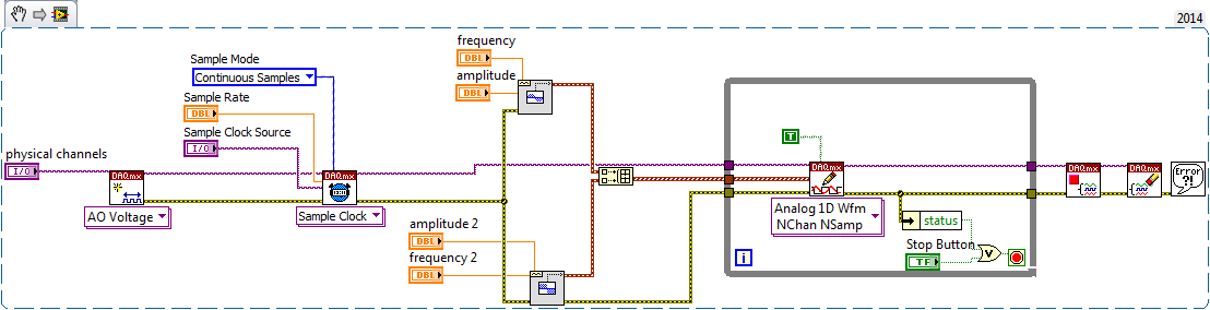
I use USB-6215, who has two analog outputs and having to send the same waveform through the analog outputs two of my DAQ. at the same time. in fact, I have a text file consisting of a code word (please see the attatchment) with dt, freq and annex 0 in the first column and other columns contain the word coded. Withe the help of dt, the rate and the data I did a waveform with the wave of construction VI. I am able to write this wavefrom through an analog output A01 right now. I want to know how I could write the same analog waveform other AO0 out simultaneously. I use a source of external triggering via PFI0 to be triggered. for now, I use the write.vi DAQmx (analog channel 1 DBL 1 d N samples) and DAQmx create virtual channel.vi with dev1/ao1 as the physical channel. For more information, I am attatching the program along with the text file. Please see page 2 of my structure of matter in the VI attatched.
Thank you.
Kind regards
Raja
Hi Steve,.
his works now. I changed the instance of writing DAQmx for analog waveform samples N channel N. still, I now that a single waveform. How could I do like two like it (writing DAQmx) will not accept a single waveform as the entry as the number of channels in the task will now be 2 where, under the waveform has an exit.
Kind regards
Raja
Tags: NI Hardware
Similar Questions
-
Sending of different waveforms on two separate analog output channels
Hello NOR community,
I am trying to send a note to say 100 Hz signal on one of the channels on my computer USB 3101 FS Measuremnt and a sinusoid 300 Hz on another channel. I've seen a lot of soultions to this problem, but I do something wrong in my attempt to imitate. As a result of the use of a product of MC, I use the library instead of DAQmx Ulx, but the Vi is virtually interchangeable features wise. In any case, I managed to send two signals (see annex VI), but they are still the same in terms of amplitude and frequency. In other words, I get the same signal on both channels as opposed to the two different signals of different frequencies.
Thanks for your suggestions,
Leo
Hi Lemmeneger,
I have reproduced what you're trying to do, but using DAQmx since I did no material of MC. And had no problem sending two different analog ouptuts.
Could you try to wire the errors? and let me know if something doesn't appear! I do not see a problem in what you are trying to run
Kind regards
Caroline
-
Interleaving of samples: two outputs analog (tables with different lengths)
CHAN                   AOCHANNEL1       AOCHANNEL2       AOCHANNEL1           AOCHANNEL2       .. .and so on
SAMP                   * * * * *           *              * * * * *              *           .............and so on
Hi guys, how could I go on the interlacing of two arrays of different lengths in a two-channel analog output?
In the illustration above, for example, I like to write 5 values in channel 1, followed a string of unique value 2 and so on...
I use DAQmx library controls to achieve this (not LabView).
I am able to write unique values each time a task is opened without any problem, I was wondering if I can interleave the berries so that values are buffered and tasks are performed with greater haste.
best regards,
Ravi
target met: I've made the following changes:
CREATION OF TASK 1
CREATION ANALOG_VO channel 1 & channel 2 in TASK 1
CONFIG. CALENDAR OF TASK 1CREATED some TENSION with SAMPLES interleaved pre
WRITING TASK 1 VALUES
TASK 1 STARTED
DAQmxCfgSampClkTiming(taskHandle1,"",SAMPLING_RATE,DAQmx_Val_Rising,DAQmx_Val_FiniteSamps,2*SAMPLE_SIZE_WX) -
Example of Code OR-DAQmx (C/C++) for playback of 8 differential analog inputs on USB-6215?
Are there examples using the API C/C++ of NOR-DAQmx in an application that illustrates how to read all 8 analog channels (differential) on a device USB-6215 or similar? I can find examples to read only one channel, but nothing for multiple channels. When I try to read all 8 channels, I get only entry on the first channel. Any help would be appreciated.
Kind regards
Bob
Brandon:
Thanks for the tips. I have it working now.
Kind regards
Bob
-
is it ok to connect two outputs analog voltage in series?
Ok... I have a PS-210 FieldPoint... basically an analog voltage output 0 - 10V, 200mA per channel (with additional external power supply)... my question is... can I plug two channels in series? Love how I can put two AA batteries in the series... and then to double my blood pressure? and then check my two separate channels and the sum of the tensions would be assujettirait I have my load in?
Thank you!
No, you can't. The channels all share the common side of their outputs. If you've tried to hang them in the series, you have wind of short-circuit one output from the ground.
The reason for which you can do with batteries is that the tensions are floating. There is no common reference between the negative terminals of both batteries.
-
rate real output analog OR-6351
Hello
I am trying to create a generator of arbitrary signals on both channels DAC on a NOR-6351.
Everything works fine - with the exception of the fact that I'm not sure what is the real rate of analog output.
This is quite crucial for me, I have calculate my wave based on Fourier transformation fast discrete - to get the correct frequency, so it is important to know the rate of real output.
The card has a rate of update AO 2.86MS / s,. The property timing - real sample clock frequency product also these 2.86 MHz.
When I then try to use the same frequency to generate two analog outputs, it always tells me that it uses 2, 86 MHz, even though the notebook loads says only he can produce 2 ms/s when using two channels.
So my question is, how to determine the actual flow of outputs analog?
And what is the rate of real output of the DAC?
Concerning
Jørgen
I just had a scope attached, while generating a sine function at 300 kHz, the rate of 2.86MS / s.
The scope read 300 kHz, which must mean that the DAC will actually to 2.86MS / s, otherwise the resulting waveform would have been to close to 200 kHz.
I have this will mark it as resolved, although I have not yet crazy understand why it is able to output at this frequency.
-
Producer consumer with inputs and outputs analog and digital
Hello world
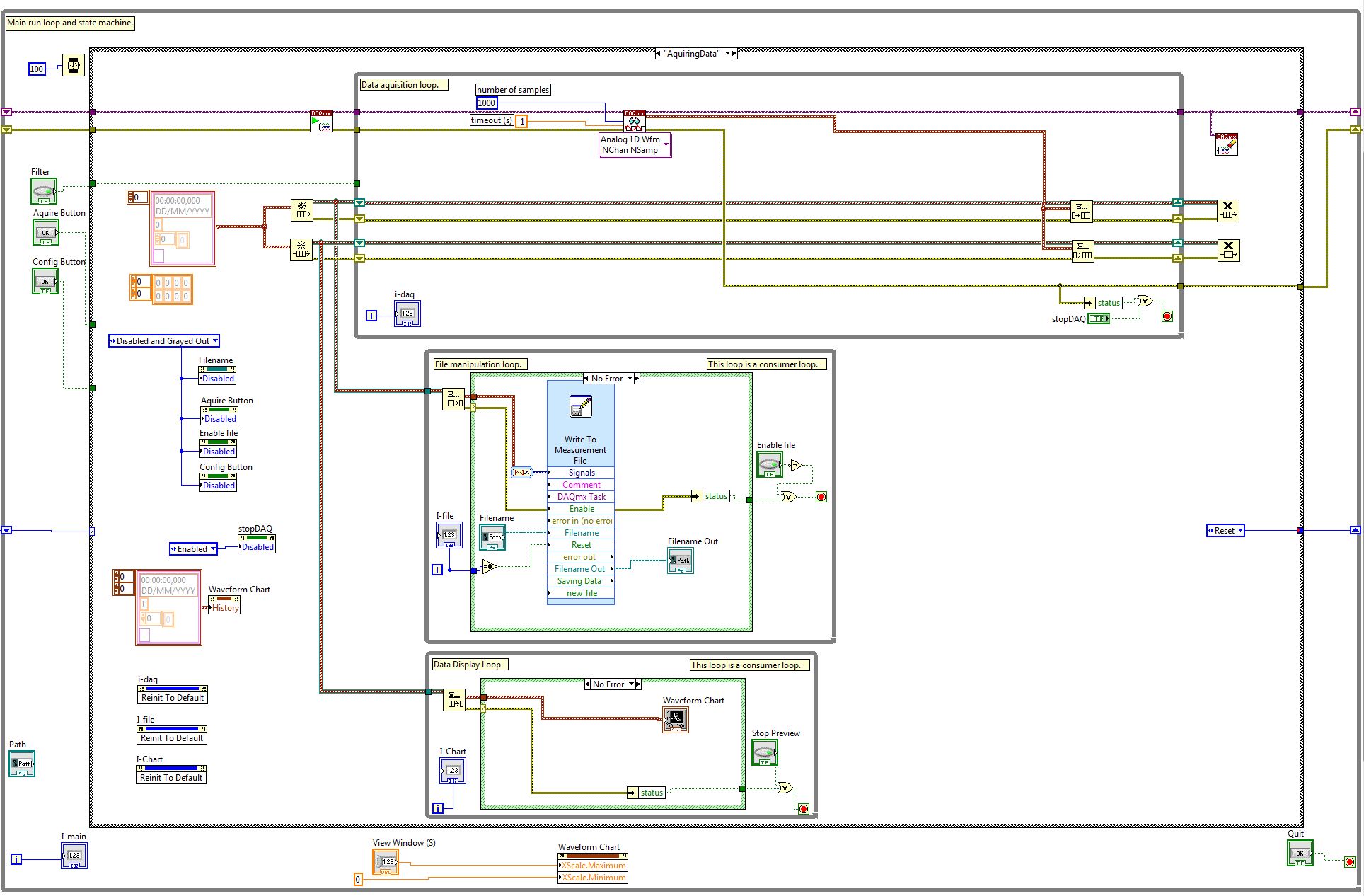
I'm working on a program of control system for some practical test work. Currently, I am working on the data acquisition of the Labview program component. My architecture is consumer-product loops with a what. My system will have analog inputs, outputs, analog inputs and digital outputs. It is not a criticism of time sytem, but I wish that all the acquisition of data to synchronize. I enclose my program because it is at the moment. I have difficulties to get all the data in the since that I have two types of data. In addition, I don't know if I have synced the four sequences of read/write correctly. I would be very happy if someone could take a look at my program and give me some advice. Thanks in advance.
-
USB-6009 software simultaneous timed output analog
Ladies and gentlemen,
I worked on a LabVIEW interface to a potentiostat I designed and built. I'm not very experienced with LabVIEW, but do they have experience with a variety of other languages (I had originally intend to use an FPGA for this, but he has been asked to write a LabVIEW VI first) programming.
The goal:
I want to output a voltage (initially consisting of ramps) signal and measure the voltage with an operational amplifier configured as an ammeter of feedback (using resistance feedback and voltage value to calculate current) connected to an electrochemical cell. The resistance of feedback is selected by using an automatic selection function (although I wrote a version prior to manual control) as TTL values using the DAQ Assistant to select relevant MUX channel outputs. I then try to save the data in a spreadsheet.
The problem:
I use an acquisition of data USB-6009, and I know that there is a hardware clock. Read all about him seemed obvious, the best way to the waveform of the output voltage used DAQmx package to define a function of writing in a loop that is clocked by the software. The problem I have is that I can't synchronize the output to the input with reliability and I have also some errors related to resources DAQ being reserved (error 50103). I think the way to solve this would be to convert every equivalent DAQmx DAQ Assistant and try to group their execution - this is where I fall. I tried to write a simple VI who shared a loop clocked by the software to read and write but had problems related to the value of min HAVE (error 200077).
General issues:
How I begin the process of read/write (with a Boolean switch) is very weak and doesn't feel not robust. Ideally, I would like to some form of indicator to warn the user when the read/write process is running and when it ended.
My error handling is terrible, but I find no big thing to read about the basics.
I use only a sequence of no and I think I should have more.
Once I hit the beginning, VI requires the file name for the worksheet - at first, I was afraid that data would be entered correctly, but I think it's okay because the file is generated and then changed. It would be better if the user asked for the name of the file once completed the data collection.
Any suggestion or help would be greatly appreciated. Thank you in advance.
Sincere greetings,
Julius
The hardware supports timed 6009 entry analog. Even with the 1Samp mode, your code could be simplified with a single task and several channels (dev1\ai0:1). Then use Nchan 1Samp.
-
Output analog, the USB-6009 case - can I use DAQmxWriteAnalogScalarF64?
I just got a NI USB-6009 and I try to use the outputs analog simple.
I'm running on a Mac, so I'll try to use the API OR-DAQmx Base 3.2 C (downloaded from here: http://joule.ni.com/nidu/cds/view/p/id/1078/lang/en). This is the most recent version of NOR-DAQmxBase, I could find.
I try to do continuous analog output on the 6009, which does not have a built-in clock. I was hoping to do the sync software and just new output values when I want to.
I can't get an output of database to work. Other messages and the example of Windows files, (e.g., National Instruments/NOR-DAQmx Base/examples/ao/MultVoltUpates-SWTimed.c) it seems that the best thing to do would be to use the DAQmxWriteAnalogScalarF64 function.
However, this is not in the Mac version of the C API of NIDAQmxBase. There is actually an entry for this in the NIDAQmxBase.h file, but it is commented out. Anyone know why? Is it possible to use this function for the analog output on request on Mac?
Thank you.
Clement
I have NEITHER-DAQmx Base installed 3.2 on a 10.4.11 system. One of the examples files 'genVoltage.c' calls DAQmxBaseWriteAnalogF64. I was able to compile and run this example with a USB-6009.
The DAQmxBaseWriteAnalogF64 function would work for you?
My guess is that, since you can write a scalar value with DAQmxBaseWriteAnalogF64, DAQmxBaseWriteAnalogScalarF64 becomes superfluous. The example provided with the installation shows how to write a unique value (i.e. scalar.). I pasted the code of OR below.
int main (int argc, char * argv [])
{
Task settings
Int32 error = 0;
TaskHandle taskHandle = 0;
char errBuff [2048] = {'\0'};
Channel settings
Char [] = "Dev1/ao0" chan
float64 min = 0.0;
float64 max = 5.0;
Sync settings
uInt64 samplesPerChan = 1;
Writing data parameters
float64 data = 3.25;
pointsWritten of Int32;
float64 timeout = 10.0;
DAQmxErrChk (DAQmxBaseCreateTask("",&taskHandle));
DAQmxErrChk (DAQmxBaseCreateAOVoltageChan(taskHandle,chan,"",min,max,DAQmx_Val_Volts,));
DAQmxErrChk (DAQmxBaseStartTask (taskHandle));
DAQmxErrChk (DAQmxBaseWriteAnalogF64(taskHandle,samplesPerChan,0,timeout,DAQmx_Val_GroupByChannel,&data,&pointsWritten,));
Error:
If (DAQmxFailed (error))
DAQmxBaseGetExtendedErrorInfo (errBuff, 2048);
If (taskHandle! = 0) {}
DAQmxBaseStopTask (taskHandle);
DAQmxBaseClearTask (taskHandle);
}
If (DAQmxFailed (error))
printf ("error in DAQmxBase: %s\n",errBuff); ")
return 0;
}
Hope this helps!
-
Synchronization output analog and an entry for imaging
Hi all
I'm stuck in my higher studies project and really need help. I tested an imaging system, where one uses two mirrors MEMS to analyze the sample and a tube set (PMT) allows to acquire voltage signals and translate them into images of scanning laser.
I use the same DAQ card for input and analog output. The DAQ card sends features X and Y of the MEMS mirrors so that the reason for scanning 2D starts left to right and up and down.
Scanning rate: 131500 pixels per second.
Size: 1170 by line, 514 ranks in total pixels.
Thus, the mirror will scan 601 380 pixels per image, which takes approximately 4.57 seconds to complete. I almost finished this part in LABVIEW.
However, only a part of the scanned pixels are read by the PMT. We want to get an image of 512 x 512 pixels. For example, the PMT works like this:
(1) the sampling rate is also 131500.
(2) skip the first row.
(3) starting at the second row, the PMT will jump the first 329 pixels, read in the next 512 pixels and skip the rest 329 pixels again. Then, it moves to the next line.
(4) jump the last row.
My approach in the plate sequence
(1) ignore the signals of all 841 (1170-329 = 841).
(2) create a loop for, run 512 times.
(3) in each loop, first jumping 658 signals (329 x 2), then read the signals then 512 MB.
(4) wait 1499 pixels left to complete the digitization (1170 + 329).
Problem
The mirror and PMT must start and finish at the same time running. However, when I run my VI for the analog input and create the image on the Panel, it takes 5.7 seconds to complete, which means that they are not at all synchronize. It seems that there is some unexpected time in the loop for, but I don't know how to change the code to meet the requirement of calendar.
Please see the attached VI. Any help is greatly appreciated.
~ Sheng
My approach in the plate sequence
(1) ignore the signals of all 841 (1170-329 = 841).
(2) create a loop for, run 512 times.
(3) in each loop, first jumping 658 signals (329 x 2), then read the signals then 512 MB.
(4) wait 1499 pixels left to complete the digitization (1170 + 329).
Consider this: add up all these pixels, both those you want to record and those you want to ignore.
If I read you right, that would be:
841 + 512 * (658 + 512) + 1499
Regardless of this number, set up a task that many samples and record the whole bloody thing. Let the time of equipment for you.
Then, AFTER that data are in hand, pass by and throw the first 841 points, then for each loop, throw away 658 and keep 512... etc.
IOW, let the MATERIAL which made the better material: precise timing.
Let the SOFTWARE do what does best software: weird logic.
-
I use an app that plays back "multi-way" called reading. It has a feature called auto pan which has a toggle button, but when I turn IT says, "Only works with 2 iPad release." My iPad 2 Air apparently has this feature, but the iPad 2, that they have in our rehearsal studio does not work. I'm trying to find out what iPads have this feature, but looking at the specs on the Apple website is not to give me this info! Can someone help me? And I'm not sure I understand because the headphone jack released in stereo must be some different internal separation type pass...?
Thanks much for any help!
What to do with it, their Web site?
AutoPan
Enable AutoPan in parameters to pan the ClickTrack and Guide to the left and all other channels to the right. CustomMixes are made this way before, but you should choose Auto-pan to separate the Guide and ClickTrack for multitrack in the show alive. AutoPan is necessary when using two outputs.
and
Multiple output
Using a compatible USB Interface, you can send several of your iPhone or iPad to your soundboard Audio outputs. For a list of devices compatibleclick here. (Device upgrade Premium) (which takes you to http://www.multitracks.com/products/playback/supported/)
-
Outputs analog USB-6211 won't go below 3.375V
I use a 6211 to pulse output 0 - 5V outputs analog using an external clock as a trigger, and after successfully using the system for a while I finished with a question where none of the channels AO out lower voltages at 3.375V. My current theory is that I can have exceeded the current 2mA max output, but I don't know how, which would result in what seems to be a permanent tension.
I have reset the device and tried using other computers, but the problem remains. I ran the diagnostic utility and it fails part AO when it tries to output 0V and reads the 3V but he gave no further information. All other parts of the diagnosis are very good.
Any help would be appreciated, I'm a little stuck on my diagnosis.
Hi Airgunner1,
I'm not quite sure because I've never worked this side of the process, but if you call in they should be able to tell what your options are. Sorry I can't be more helpful!
-
How to trigger and outputs analog and digital Outout tasks begins on a counter to start?
Hello
I'm trying to synchronize the start of a task outputs analog, a task of digital output and a task of counter. I want to start the counter to serve the master trigger and analog and digital tasks to synchronize his departure.
I guess I need something like:
analogOutputTask.Triggers.StartTrigger.ConfigureDigitalEdgeTrigger ("?", DigitalEdgeStartTriggerEdge.Rising);
digitalOutputTask.Triggers.StartTrigger.ConfigureDigitalEdgeTrigger ("?", DigitalEdgeStartTriggerEdge.Rising);
analogOutputTask.Start (); Slave 1
digitalOutputTask.Start (); slave 2
() counterTask.Start; n / / master
Where? is a string specifying a command source for the beginning of the task of the meter. However, I can't find what this string. Any suggestions?
Thank you!
-Jon
Just FYI, the solution to this problem as well as some other ones is encapsulated in a short example .NET, I created. It is on the Web site of EITHER:
http://decibel.NI.com/content/docs/doc-15500
This project shows how to synchronize all your analogue/digital outputs through tasks and forums in terms of synchronizing Calendar and start clock.
-Jon
-
FPGA output analog fastest? (RIO 9641)
Hello world!
I read only analog output have about 38 tics. clock 40 MHz (RIO 9641)
My RIO gives me tics 107 = 112 - 5 analog outputs for the 1 iteration. If DAC cycle... The entire cycle takes (112 * 160 * 25th-9) for DAC 107 * 160 * 25th-9 = 428e-3 s always takes DAC, and I need more quickly.
How to set up outputs analog faster or rebuild program?I need the fastest analog output, is it possible?
Thanks for the help!
Hi togoto,.
Please let me know if I'm struggling to understand what you're trying to do, but the fastest, the analog output of the 9641 can update is 120 ticks by update. Which is based on the specification of the material on page 44 of the User Guide and the restriction that you touch. Therefore, I don't think you'll be able to get it down to 40 ticks.
-
Reduce the size of a file created by "write to waveform.
Hello
I'm using labview in 2012 and I have a problem with the size of the tdms file generated by the function "write to waveform. The data is real time 16 channels in a series of X NI USB-6343 and is composed by the gains of the voltage on the y-axis with the absolute time on the x axis (waveform format). The size of the file is reached a Go command within a few hours. Is it possible to reduce the size of this file? All configurations on the component?
Thanks for the help.
Best regards
Marcelo Nobre
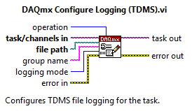
Yes indeed, there is a better way. Instead of using writing on file express VI measure, try adding the DAQmx logging into your task DAQmx (before starting the task):
This method writes the raw binary data unadjusted to the file (2 bytes per sample because it is a 16-bit data acquisition card) with scaling of information in the header of the file. In the example you posted, you write the data which are already put across to the file (double 8 bytes for example). What will make this change you expect to reduce your file size by ~ 4 x.
If you wish you can compress the files once you have finished writing to them for further reduction of size, but there is no support to achieve so that you are currently writing in the PDM file. In addition, you will need to unzip the file until you can access the data in the .tdms file. You can probably get good results with something as simple as the data stored in a .zip file.
Best regards
Maybe you are looking for
-
Can I back up files with time machine iCloud. Seems not so, are there alternatives?
I want files on mac, in the clouds and on local separate media seems quite difficult to achieve for a sensible backup plan. I looked for solutions and there are various tips on if time machine backup of documents Mobile ~/Library but I can access in
-
Where can I find a website for repairs?
I am looking for a repair that would describe how to disassemble and repair my Toshiba Satellite A205-S4607
-
3170se Pavilion dm4 broken hinge
Hi all I have Pavilion dm4 3170se 2 years and my share of hinge laptop is broken... It is really difficult to close. I tried to shut it down, every time, I heard something broken sounds so I left everything to close. My laptop needs hinge hinge and
-
OfficeJet Pro 8610: Install the HP software
Hello! I have a HP Officejet Pro 8600 and a HP Officejet Pro 8610; When connected to my wireless router. I have a new laptop Lenovo with 10 windows and I want to know if I need to install two (8600 and 8610) Officejet software under Windows (to print
-
OfficeJet HP 6600: printhead missing, not detected or ill-posed
Ink is not empty and is correctly installed, but above message continues to appear and it give no details about the problem.