frequency of measurement of digital random signal
Hi all.
I want to measure the frequency of the signal. This value will be sent to any other device to vibrate the vibrator according to the value.
For example, I want to measure this signal:
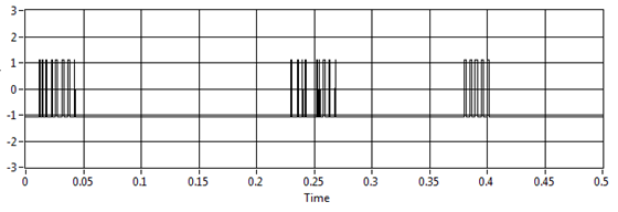
I try to use your vi and extract single signal measure vi, but the result is not fair, for example, if I have no pulse on the graph the result is 11, 5 Hz (it should be 0 Hz)
I use assistant NI USB-6210 and acquisition of data to get the data from the sensor
Laughing out loud! All that motivates you... I don't see attachment. I commented on the block diagram on the vi attached which may help. What you can do in your data acquisition program, use is get the queue with the name of data. Then take the waveform of the DAQ assistant and use waveform components get to retrieve the values of the real signal (-1 to 1). Now use a loop with automatic indexing on table of signal and inside use enqueue to place each value of the signal on the data queue. In the joint programme filter, you can either copy the lower node in your program for the acquisition of data, or remove the loop of high signal generation and run them in parallel. The nice thing about the queues is that they can transport data between different vi on the same computer that the name is the same. If you want to do something with the frequency measures, while you can use a different queue for buffering of the data out of the loop of measure.
Good luck!
Tags: NI Software
Similar Questions
-
How to measure the digital output of the linear actuator on USB-6009?
Hello
I am a new user of Labview and need help to measure a digital input signal.
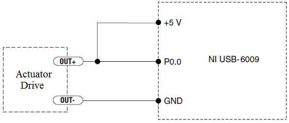
I have an actuator Bimba Original line electric with a motor continuous integrated with encoder, drive and the controller. The drive has a programmable digital output that I put as a tachometer output that emits pulses of square wave 100 per turn of the engine. I put the engine to make a total of 56 rev in 22 dry. I want to measure the speed of motor rotation labview real-time and synchronize it with a few other analog input signals. I wired the actuator for the USB-6009 case as shown below.
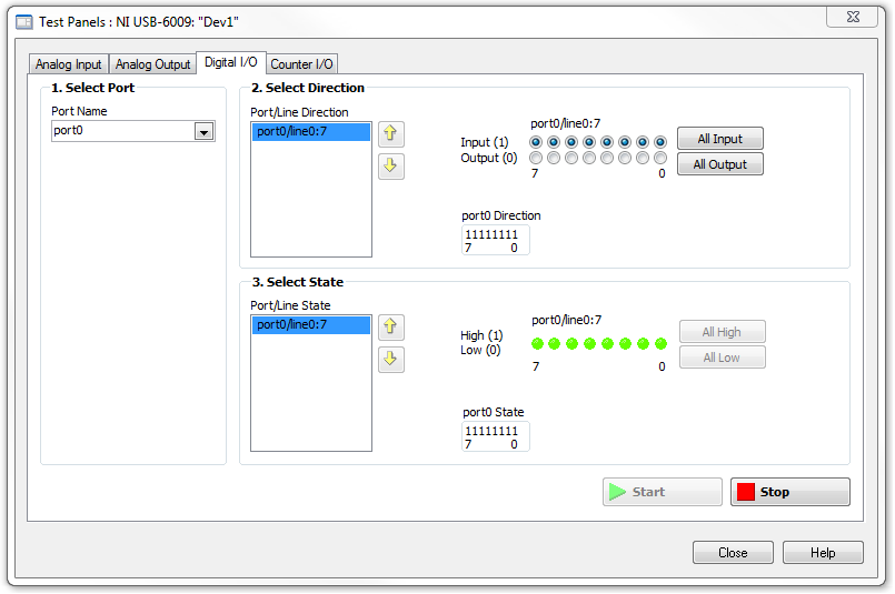
I opened the test i/o digital USB-6009 Panel and fix all the lines of port 0 as inputs. However, when I click on start and run the actuator, p0.0 led flashes, as indicated below.
Shouldn't the led blink in response to revolutions of engines?
I want basically to collect the drive pulse signals and convert them in rpm on labview.
ahsan2 wrote:
I have it wired correctly?
It would help if you do not attach the HIGH signal. Remove the + 5V in the circuit.
-
Duty cycle of measurement using digital inputs DAQ
Hi all!
My system has a PXI-8269 card and I want to measure the duty cycle of the Digital PWM signal generated by a device.
To acquire this signal, I'll use a digital DAQ (PFIx) instead of a counter of data acquisition (CTRx) (they are already used for other applications).
The search of the database of examples, I found live who use meters. So I wonder if it is possible to do that and how could I.
Thank you!
Sorry, the correct reference is PXI-6289.
I was determined to acquire a digital waveform, converting it to an analog waveform and then using the correct function in the range of functions->-> Analog wave.
Thank you!
-
generation of digital, analog signals read snap SMU-6358
I have two SMU-6358 card and I want to send control signals to my camera and read the analog signals from the device with them.
For the digital control signals, I tried to set up a system where I specify the identifiers of the pins, bring them into arrays of strings - the respective waveforms would be collected in the tables too - and I transfer them to a VI of inputs/outputs multiples that puts digital waveforms for the cards output pins.
I developed this code here, but it doesn't seem to work. I can't understand how I can convert the string and form table wave to meet the requirements of the input/output VI or which another VI I could use to do the job. Or is there a smarter way to do it?
Thank you
Kriváň
Dear Kriváň
Please find attached the VI in LV 8.6 format. Also, I HIGHLY recommend to rearrange the front panel and which makes it neater, your code is very hard to read and not structured at all. I hope this helps!
-
Frequency of measurement with cDAQ NI 9402 chopper
Hello world
I'm new in the world of the cDAQ and try now just get a frequency of a TTL signal output chopper. I confirmed 23 Hz frequency on an oscilloscope. It's a nice clean 5V square wave, but when I try to measure the frequency in labview using a VI (dig frequency of continuous measurement) example, it comes to expire. Trying to look at the entrance of the signal in express shows signal an incompatible digital signal that is around 3 Hz and clearly the result of the port being interviewed for entry too rarely. The final objective is to get this work with the labview vi PLL is a detector lock in the amplifier, but first of all, I have to be able to measure and to read correctly this frequency.
My hardware is a cDAQ-9174 with a 9402 OR for use with the digital input. I don't know it's important, but the 9402 module is in slot 3 and I'm on channel 0. The software is labview 8.2 with DAQmx 9.1. Is there some timing issue material or the definition of I'm missing here? Any help is greatly appreciated, thank you!
Hi Skaboss,
Counters have multiple terminals (source, the door in and out), which map to separate on your NI 9402 PFI lines. For the measurement of the frequency, the default input terminal depends on the method of measurement (low frequency, high frequency, wide range). Here's the relevant section of the NOR-DAQmx help (which is on the Start Menu):
Connections of signals C series for counters
The following table lists the default input for various measures of meter terminals. You can use a different line of the PFI for one of the input terminals. To edit the entry PFI for a measurement, use channel NOR-DAQmx attributes/properties.
NEITHER 9402 and NI 9435 (4 channels)
Measure Ctr0 Ctr1 Ctr2 Ctr3 Number of edges Edges: PFI 0
County Executive: PFI 2Edges: PFI 3
Branch Count: PFI 1Edges: PFI 1
Branch Count: PFI 0Edges: PFI 2
County Executive: PFI 3Pulse width measurement PFI 1 PFI 2 PFI 3 PFI 0 Duration/frequency measurement (low frequencies with a meter) PFI 1 PFI 2 PFI 3 PFI 0 Measure of duration/frequency (frequency with two counters) PFI 0 PFI 3 PFI 1 PFI 2 Duration/frequency measurement (wide range with two counters) PFI 0 PFI 3 PFI 1 PFI 2 Measure semiperiod PFI 1 PFI 2 PFI 3 PFI 0 Measurement of two-Edge separation Departure: PFI 2
Stop: PFI 1Departure: PFI 1
Stop: PFI 2Departure: PFI 0
Stop: PFI 3Departure: PFI 3
Stop: PFI 0Measure of position A: PFI 0
B: PFI 2
Z: PFI 1A: PFI 3
B: PFI 1
Z: PFI 2A: PFI 1
B: PFI 0
Z: PFI 3A: PFI 2
B: PFI 3
Z: PFI 0Alternatively, you can override the default with the CI. Freq.Term channel property.
Brad
-
USB 6008 digital output signal
I am VERY new to LabView and have been racking my brain trying to get digital output of my USB-6008. All I want is to be able to get a signal of + 5 V of my digital output when I click on a button. This signal opens a valve on a system I see so when it is pressed, it must stay open until I press the new button. It seems simple enough to me, but I'm not too familiar with LabView. Help, please!
Stripling07
You must first take the LabVIEW tutorials and then look at the links to get started with DAQmx .
The simplest program would be with the DAQ Assistant. Drop it on your schema, and then select digital output > digital line. Select the line when the wizard has completed, click OK. Wire a Boolean value in a table to build and the output of which is connected to the data entry. That's all. You can test the output of MAX (Measurement & Automation Explorer) with the test Panel. Do NOT test with your connected tap. Your valve may require more current that can provide the 6008.

-
How can I improve my 2 digital output signals calendar?
Hello
I use a NI DAQ Pad-6015 (usb) with Labview 8.5 and XP to generate 2 digital outputs (high for the first 500ms and 600ms high for the second). The moment didn't need to be very specific, so I use not the 2 outputs hardware clocks. When runing of VI, and measure the length of the outputs with an oscilloscope, I get s 520ms and 640ms. This isn't a problem, but I still want to know, if I'm doing the right thing in my program, or if it is possible to improve it?
Thanks for your help,
Kind regards
Marc
Hello
Using all your advice I have exact measure now: only 0 to 4ms delay for signals from ms 500 and 600 using the NI DAQPad-6015.
PS: Timmer was right regarding the notice of usb. With my previous program when you use a card PCI of 6229, I had only a difference of 10 ms instead of 20 ms with the usb one.
Thanks for your help,
Kind regards
Marc
-
Frequency counter measurement crashes when you're away point zero (NI USB 6343, error-200284)
Members of the Forum,
I have problems with a measure of the frequency on a DAQ Mulitfunction of NI USB 6343 X series. I use the meter 1 (door axis for frequency signal, PIN to DGND 82 77). The couple HBM T10F flange that I use (powered by a power supply of 24V) emits a signal of frequency between 5000 and 15000Hz with 10000Hz being the zero point. Couple flange has a capacity of 5kN.m (15000Hz = 5kN.m; 5000Hz = - 5kN.m).
I have been using the VI attached for a few months now without any problems. Now, the VI works fine as long as the couple remains inside a few hundred Hz of the zero point. However, when the frequency increases further reading couple begins to freeze and finally I get either of these two errors:-200279 or-200284 related samples is not not available. I noticed that the light on data acquisition close compromise during these periods of frost.
Here is an example step by step my problem using cal shunt of the flange of the couple:
1. I have run the VI and couple bed properly around 10000HZ (Active light, indicator light ON)
2. I have apply the excitation of 5V to the shunt cal and frequency climbs to about 50% of the ability to couple brackets (as it should)
3. as soon as I remove the excitement 5V playback freezes and the light on the acquisition of data.
4 if I apply the 5V once again, until the timeput occurs, the led turns on and the acquisition of data reads the signal correctly.
This type of problem would be more DAQ-related or is it the flange of the couple itself.
Thanks in advance,
Mike
Solved.
I did some troubleshooting this morning and it turns out that the vibrations of the system had not tightened a screw that was connector to the stator flange torque causing a bad electric signal of the torque flange itself.
Everything works fine again.
-MB
-
G20-120: how to choose digital airborne signal to Qosmioplayer?
I have a G20-120 with analog/digital TV tuner.
I now wish to leave the DVB - T tuner to receive airborne television signals. (Try mine with analog signals only)
I can't find how? Any person who knows or who succeeded with that?MODIFIER
Hello
It would be very interesting to know what version of the Qosmio player you have.
I found this official document to support Toshiba:
http://support.toshiba-tro.de/KB0/TSB6101A90000R01.htmThere, I found information that 4.3 Qosmio player and older Version does not support the DVB - T signal.
The DVB - T signal can only be used in the Microsoft operating system -
Measure Z to a battery encoder encoder pulse frequency to measure the speed using a 6034 E card
Hello
I want to measure the speed of a motor that has an encoder to encoder hung on battery. It provides impulses 3 A, B and Z I uses a PXI 6034 E card. I wanted to know if there are any examples/ideas that could help me with this (I'm new to digital programming in Labview). I moved to NI Daqmx 9.8 recently of the old version that has supported the existing codes and therefore being updated the code. I also want to know if an external clock source is needed to do this. This.
Hello
There are several examples in the finder OR example (you can get here by going to help > find examples in a window of LabVIEW). You can browse examples of Encoder on input and output material > DAQmx > entry counter. You should be able to find some examples that will be useful.
In addition, this link is a good resource to get started using DAQmx: http://www.ni.com/white-paper/5438/en
Thank you!
-
Hello
We need power RF amplifier with a function generator to create plasma in an ion source. The signal pulse duration must be 1ms long, repeated twice per second.
Today, we work in the following way: we spend the RF with f0 (aprox 1,995 MHz) frequency. After 20, we send a trigger signal passing frequency f1 (aprox 2.005 MHz). We keep this frequency for the rest of the pulse. However, the plasma that we generate is not 'constant' or stable during the whole impulse. If we smoothly change the frequency during the pulse we could improve.
We would like to do: use the frequency sweep: rather than use this frequency hopping, we would like to move smoothly f0 f1 (frequency scanning). Then F1 to f2.
As we have a PXI for data analysis, we believe using the arbitrary function generator of NOR: 5406 of NEITHER allowing the frequency sweep. However, in the book loads, it is not very clear, and I have a few questions:
-We can create a "list of frequencies. In the site OR below, it shows that the "minimum of Step' is 1.28us, which would be ok for us (I understand that the"minimum duration of Step"is the minimum time between 2 frequencies). However, the manual of the device "NI PXI/PCI-5402/5406 specifications" said the frequency list has a time step of 1 ms to 21s. What is the good?
-It is also said that the "duration of minimum list" is 1 s. For us, need us a shorter list that 0.5 seconds (we need to repeat the same pulse twice per second.). Is it possible to do what we want?
-At the end of the day, we would like to implement a control loop which modifies the list of frequencies in real-time.
http://zone.NI.com/reference/en-XX/help/370524L-01/nisignal_generators_help/features_by_device_smc/
Thanks for your help.
Best regards
Jose.Hi Jose,
You're right about the inconsistencies of the documentation. The minimum step was of 1 ms, but was changed to 1.28 µs to driver version 2.6. The help document has been modified to reflect that, but the specifications were not. I'll make sure that attaches.
The length of the minimum list is not listed in the book loads, and the latest version of the help the signal generators OR (driver version 2.9) lists the minimum list than the 1 step length. Aid has changed to the driver version 2.6.1 to clarify that the 1s meant 1 step. I've attached a screenshot of the help of the most recent.
There is an example that is installed with the NOR-FGEN driver called "Fgen Sweep Generator.vi". I would recommend from this for your application.
I hope that some of the inconsistencies in our documentation brightened. Please let us know if you have any other questions.
Elizabeth K.
Generators of signal produced technical support engineer
-
Amplitude measurement of a continuous signal in a given time window
I'm working on an acquisition system that acquires a continuous signal of 250 kHz. My goal is to measure the amplitude peak-peak of the first reaction of signal, the problem with my setup, this is the first part of the signal is always higher than the part of the signal that I'm interested. If I try to use the measure of max from Ridge to ridge of signal VI then responds with the measure of Ridge Crest of the initial part of the signal. See the attachment for a better understanding, I would still like to view the raw signal as is, but I would like to measure the peak voltage at peak of the signal between the yellow sliders.
Thanks in advance...
If transient initial always occurs in the first 12 microseconds, you can use any subset of table or similar wave function to retrieve the last part of the wave. Then use the measurement from Ridge to Ridge on this subset.
Lynn
-
How to set the clock as a Digital Out Signal in the C API?
My problem is simple, I'm looking for a way get the my device of the series E clock signal (6254) to a digital camera offline. Is it possible to do in the C API? If yes are there docs everywhere where show me how do?
Hi neurostu,
Yes, there is a way. The function is called DAQmxConnectTerms. "" "" "You can find the definition of the function in Start ' programs ' National Instruments ' NOR-DAQ' text Code support" using NOR-DAQmx C reference. "" "On the left, select OR DAQmx C functions" advanced"routing of the Signal'. DAQmxConnectTerms
-
How can I write to the spreadsheet or measurement produce the following signals
Hi friends!
I wonder how to write in file worksheet or to measure 1 and 0 of my assistant DAQ on this VI:
It's the same VI like this: http://zone.ni.com/devzone/cda/epd/p/id/6405
Hey,.
You place the measurement file Express VI on your blockdiagram write and pull a cable since it's 'signals input terminal' to 'data' of the DAQ Assistant Terminal. Like this:
Christian
-
USB-6501 384 bit synchronized digital output signals
I need three digital signals (please see the attached file) to control a device, a signal is the clock signal, one is a continuous data signal 384 bit and another strobe signal that informs the device start and stop data. I have a USB-6501, this task can be achieved? I don't know how to write a 384-bit with DAQmx write signal, because it seems to support up to 32 bits. And it will be difficult to synchronize?
Thank you!
Hello the Stork
If you send 384 bits sequentially in a digital line; and running a timed software application, this would be possible (NI USB-6501 is a programmed software). See the example VI included below. In addition, please note that avoiding the nondeterministic East and will depend on the speed of your system. If you want to continue your application with one of our DIO cards that provide hardware timing capabilities; Please see the link below for more information about these devices.
Best regards
M Ali
Technical sales engineer
National Instruments

Maybe you are looking for
-
Qosmio X 870-119 - Trackpad/Touchpad is extremely insensitive
Hi all I unboxed this laptop today and the touchpad works not very well which requires often a few seconds of "stirring" before it will work. He's also pretty nervous. I tried changing various settings including awareness and prevention of plam, but
-
Satellite 1800-804: how to boot from a USB device?
I have a 1800-804 satellite and I would like to know how to start Notepad from a usb device.
-
How can I change the function of the key chip on the Quantico. I was told you can by a representative of the US Cellular sales, but he did not know how. Motorola said I need to contact my service provider. My carrier says that I must connect with mot
-
HP Pavilion p6641f OEM dvd driver needed ram. Cannot burn cd/DVDs, programs do not see my burning device. Thank you :-) Biguer
-
How can I request upgrades for the game hearts on msn
A game loved by thousands of people is to be spoiled by a few brainless who find it easy to stall, swearing, obscene suggestions, etc.. So under mining the majority who want to just get on with the game... All this when the laws of the game that thes