Frequency of measurement with cDAQ NI 9402 chopper
Hello world
I'm new in the world of the cDAQ and try now just get a frequency of a TTL signal output chopper. I confirmed 23 Hz frequency on an oscilloscope. It's a nice clean 5V square wave, but when I try to measure the frequency in labview using a VI (dig frequency of continuous measurement) example, it comes to expire. Trying to look at the entrance of the signal in express shows signal an incompatible digital signal that is around 3 Hz and clearly the result of the port being interviewed for entry too rarely. The final objective is to get this work with the labview vi PLL is a detector lock in the amplifier, but first of all, I have to be able to measure and to read correctly this frequency.
My hardware is a cDAQ-9174 with a 9402 OR for use with the digital input. I don't know it's important, but the 9402 module is in slot 3 and I'm on channel 0. The software is labview 8.2 with DAQmx 9.1. Is there some timing issue material or the definition of I'm missing here? Any help is greatly appreciated, thank you!
Hi Skaboss,
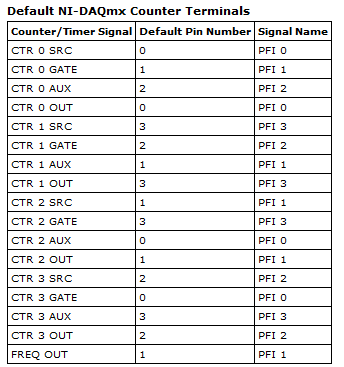
Counters have multiple terminals (source, the door in and out), which map to separate on your NI 9402 PFI lines. For the measurement of the frequency, the default input terminal depends on the method of measurement (low frequency, high frequency, wide range). Here's the relevant section of the NOR-DAQmx help (which is on the Start Menu):
Connections of signals C series for counters
The following table lists the default input for various measures of meter terminals. You can use a different line of the PFI for one of the input terminals. To edit the entry PFI for a measurement, use channel NOR-DAQmx attributes/properties.
NEITHER 9402 and NI 9435 (4 channels)
| Measure | Ctr0 | Ctr1 | Ctr2 | Ctr3 |
|---|---|---|---|---|
| Number of edges | Edges: PFI 0 County Executive: PFI 2 |
Edges: PFI 3 Branch Count: PFI 1 |
Edges: PFI 1 Branch Count: PFI 0 |
Edges: PFI 2 County Executive: PFI 3 |
| Pulse width measurement | PFI 1 | PFI 2 | PFI 3 | PFI 0 |
| Duration/frequency measurement (low frequencies with a meter) | PFI 1 | PFI 2 | PFI 3 | PFI 0 |
| Measure of duration/frequency (frequency with two counters) | PFI 0 | PFI 3 | PFI 1 | PFI 2 |
| Duration/frequency measurement (wide range with two counters) | PFI 0 | PFI 3 | PFI 1 | PFI 2 |
| Measure semiperiod | PFI 1 | PFI 2 | PFI 3 | PFI 0 |
| Measurement of two-Edge separation | Departure: PFI 2 Stop: PFI 1 |
Departure: PFI 1 Stop: PFI 2 |
Departure: PFI 0 Stop: PFI 3 |
Departure: PFI 3 Stop: PFI 0 |
| Measure of position | A: PFI 0 B: PFI 2 Z: PFI 1 |
A: PFI 3 B: PFI 1 Z: PFI 2 |
A: PFI 1 B: PFI 0 Z: PFI 3 |
A: PFI 2 B: PFI 3 Z: PFI 0 |
Alternatively, you can override the default with the CI. Freq.Term channel property.
Brad
Tags: NI Hardware
Similar Questions
-
Measurement of frequency with the NI 9402
Has anyone successfully was able to measure the frequency in SignalExpress with the NI 9402 module? I have the 9402 connected to a tachometer (on a centrifuge) which puts a TTL signal. For now, I can get the light input line to work. (Right click on the project, acquire signals: DAQmx Acquire: digital input: input line.) When the tachometer completes the first round, light or the 'blip' lights indicating the sensor then goes back to the shore for the rest of the round. I would like to read the frequency of this "blip" instead. I can't understand the required parameters in Signal Express. I tried (right-click project, acquire signals: DAQmx Acquire: entry of meter: frequency) but maybe I do not have the correct settings. This centrifuge works usually between 0 and 3 hz. I have attached a picture of what I have. I am doing this correctly, with incorrect parameters? Or is there a better way to do this? I need to read Hertz over time. Thank you!
Hi Choover,
Even if you use the 0 meter to measure frequency, your singal acts at the door of the on-board clock source to measure the length (and thus frequency). This is why you must use PF1 to connect to the door of the meter. You can learn more about how DAQmx takes measurements of meter in any manual of cDAQ chassis: http://digital.ni.com/manuals.nsf/websearch/2C061605E17C7D04862578D200677B90
Brian
-
Analog inputs measures with NI6229 using the DAQmx driver
Hello
I have four different analog inputs connected to ai0 to HW 6220 ai3. I read these values with a single task, all 4 channels assigned to this task. When ai0 reads 7V, I see 0.8 V ai1 too, but I expect to be measured 0V. If I just assign ai1 to the task and measure all 4 channels, then I measured 0V as expected (although ai1 contains 7V, I just don't measure it).
Another comment 'funny', is that if I change the order in which I add channels to the task, measurement errors are different.
However, when measured with a multimeter 4-channel show tensions as expected.
Given that my calling task is can not block, I call the function
DAQmxReadAnalogF64 with timeout = 0 and numSampsPerChan = 1.
Any help is appreciated.
Thank you
Kind regards
Deepa
Deepa,
Thanks for the code snippet.
When you call DAQmxReadAnalogF64 the first time and you set a value of timeout of 0, there is a chance that the acquisition is not yet initialized. This is the expected behavior and should not be a problem. If the timeout error died at the first call, you might ignore it or set a different expiration time for the first call only. In all cases, you should drop the first value and start with the second value.
Jochen
-
Measures with the date Conference
Hello
I have to make an application, as part of my end of study project, which allows to calculate heat flow. Pour this, I have data measured with thermocouples. These data are stored on a data recorder that record these data on a .txt, .xls or .csv file (it is to be chosen by user).
I'm not very chiseled with LabVIEW.
In a Prime Minister, I tried to read the .txt file data. I can read the 1st line as I wish but not others.
So I decided to work with a .xls file. The temperatures Conference goes smoothly. For time is the date, it's more complicated. Indeed, I would like to USE date and time corresponding to each measure to plot a graph XY with the date and time X and Y the temperature of the thermocouple.
Kind regards
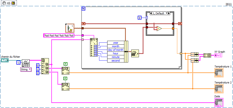
Here's an example (VI from LV2011 but attached VI en LV2010) made on the basis of your code. Comment by watch it extract the news date and time of the string and generate the the from graph XY time in seconds in X. realized very quickly, it is without doubt room for improvement but you will serve as a basis for work at least.
To define 'Structure box' serving at first as far as being 0 and calculate relative time to the following samples. Thus the x-axis of the graph starts at 0.
My time is short, I renounce other comments but I happy to answer specific questions.
-
Hello:
I am able accelerometers signals in a module of 9234, using DAQmx (I leave the joint scheme), which will be part of a program that will include other stages. When the acquisition is stopped by the "stop" button, I measure with a voltmeter between terminals connector BNC, reading 21 volts, which is the excitement of the sensor. My question is: How can I do to cut the excitement of sensors once the samples are acquired?Best regards
Jaime
Hi Jaime,
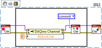
You can disable released the 9324 excitement by setting the AI. Excitation.Value property to 0.0 (see the following KB: http://digital.ni.com/public.nsf/allkb/3AD6CCE935192B4086256F6B0079CB1F).
Then, once you have set the attribute, you will incur the task to actually push this setting material (normally DAQmx will automatically engage when you start the job, but in this case, we do not want to start the task). Between your VI DAQmx stop task and your VI DAQmx clear task , you must add the following:
- GOT it node DAQmx channel property to set. Excit.Val = 0.0
- DAQmx controls Task.vi to validate your new task settings
-
HorizontalFieldManager Fix width automatic measurement with height
Hi all
I would like to make a HorizontalFieldManager with a fixed width, but automatic measurement with height. Do anyone with a good idea about it. Thanks for the help!
Thanks for your help!
Although your idea is a solution is not complete, it gives me a good idea to solve the problem.
My solution is to change my coding over a part of the first horizontalfieldmanger:HorizontalFieldManager hfm1 = new HorizontalFieldManager()
{
public int getPreferredWidth()
{
Returns the value 100;
}
protected void sublayout (int maxWidth, maxHeight int) {}
Super.sublayout (getPreferredWidth(), maxHeight);
LeftField RadioButtonField = getLeftButton();
If (leftField! = null & is equal to (leftField.getManager ())) {}
int x = 0;
int y = 0;
setPositionChild (leftField, x, y);
}
}
};
-
Hi people,
I have a challenge I'd like to discuss with you and hope to have some ideas and maybe a solution.
I have a systems acquisition (DAQ) Multifunction National Instruments NOR-PCIe-6353 means X-Series!
I would like to generate and measure signals pulse width modulation .
DRIVER:
OUTPUT:
FREQ: 0, 1 Hz - 1 MHz
Duty: 1-99%
Change the setting on the fly
(This works very well and is implemented)
ENTRY:
FREQ: 0.1 Hz - 40 kHz
Duty: 1-99%
Method of measurement: period of semi / ContinuousSamples / AsyncCallback
Here, I have problems I am running only on an Intel Core 2 Duo CPU E8500 @ 3, 16GHz.
And I want to run 2 PWM_IN and PWM_OUT 2
Low frequency work fine!
0.1 Hz - 20 kHz
It is a loopback with
myCounterReader_1.BeginMemoryOptimizedReadMultiSampleDouble (2, myCallback_1, myPWM_IN_1, myPWM_IN_1_Data);
Data = myCounterReader_1.EndMemoryOptimizedReadMultiSampleDouble (ar, on myPWM_IN_1_Data_actualNumberOfSamplesRead);
A higher frequency do not work very well!
20-40 kHz
I get exception Code of State-200279:
Attempted to read samples that are no longer available. The requested sample was already available, but has since been replaced.
Increase in the size of buffer, most frequently the reading of data or by specifying a fixed number of samples to read instead of reading all available samples would correct the problem.
Property: Value of NationalInstruments.DAQmx.DaqStream.ReadRelativeToRequested:
NationalInstruments.DAQmx.ReadRelativeTo.CurrentReadPosition
Property: NationalInstruments.DAQmx.DaqStream.ReadOffsetRequested value: 0
Task name: NI1_PWM_IN_ctr0
State code:-200279
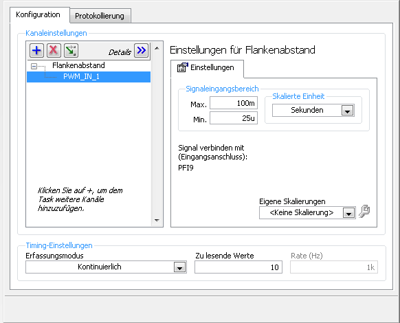
40 kHz, period is 25us = 12, 5 HighTime and 12, 5 LowTime 50% DutyCycle
This means that each 25us I get a reading of 2 samples the HighTime and the LowTime
I charge my task of Max, so here's the Setup (sorry its german):
1 can someboby you explain to me what the MemoryOptimized?
2 Zu lesende values means that the size of the buffer 10 is not much but increases the size of the buffer to say 10,000 needing help on
a longer time!
3. playback of data more frequently is not possible because the data are under tension, because it is
4 specify a fixed number of samples I der number is HighTime 2 and LowTime
5. I have does not start and stop the task! Is it better to start and stop the task each time while I still may have a new buffer?
I hope someone has an idea for!
By
Steven
Reading with 50 software we period - bad idea, you will jump impulses. Try to use DAQmx Read Overwrite property, set it to "crush the unread samples" - it will overwrite the impulses without error.
-
Error-200141 with low frequency counter measures
Hello
I'm trying to measure the speed of a rotating shaft using a laser tacho Keyence and a counter on my PCI-6601 entry.
I can't reach my vi, but I join a PNG of the section of code.
Background:
-L' tree turns to ~ 6000rom
-The counter is updated frequency measure ona climbing on board. There are 9 rising edges per revolution of the shaft.
The problem:
-If I put the vi to capture a small number of samples, it works very well.
-If I put the vi to measure the samples more 200141 occurs error "data has been overwritten before it can be read by the system.
-The number of samples, I can get without problem varies. 200 seems reliable enough. Sometimes I can get 1200, sometimes 600, sometimes 150.
-I would like to be able to get samples of ~ 2000.
-If I try to get samples continuously, I encounter the same problem.
If anyone can help with this problem it would be greatly appreciated. This is something I continue to flow upward against but so far have been unable to rectify. I'm sure I'm missing something, but I have no idea what.
Thank you very much
Martin
version 8.2
-
Cannot acquire with cDAQ in hardware mode timed using DIAdem DAC
Hi all
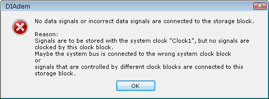
I use DIAdem DAC to acquire the cDAQ + 9225 + 9219. 9219 acquires the use of single point mode that works very well. However, I tried to acquire waveforms 50 kHz 9225 with the file attached dac. However, I found a problem on the block of the clock, as shown below.
How could I solve this problem and gain the waveform with 9225 using DIAdem DAC?
Sincerely, Kate
Hello Kate,
You must connect the NIDAQ-In1 exit the Save block block. In addition, you must change the parameters of the horloge1 block. The material is always measured in mode "DAC-kernel". "The software clock" is used for frequencies of up to 10 kHz clock (depending on the material and the PC). If you want to measure more quickly, you can use the "Clock" mode
Greetings
Walter
-
Poor quality with cDaq sinewave output
I have a cDaq 9174 with 9263 analog output module. As part of a larger system, I try to create a sinusoidal signal generator but have big problems getting something like a reasonable waveform.
I use the express VI the sinus sumulate, then in the service of analog output of DAQ assistant and just feed of amplitude and frequency values in the sine function.
Above about 50 Hz, everything works well, but 50 Hz 0.1 Hz (the range I need to use) the waveform is terrible, not sinusoidal and sometimes cut off upwards. Possible combinations tried as much as I can think of for settings of the sine and the analogue output function, without success. I contacted OR this topic and they executed my VI and say it works very well. but they do not have the same material as me to try it. I have two lots of material and the same problem occurs on both, so is not a defective hardware problem.
I use an external oscilloscope to measure the waveform and we tried two different units, with the same results on both.
-
How to make simple audio measures with a sound card?
Hello
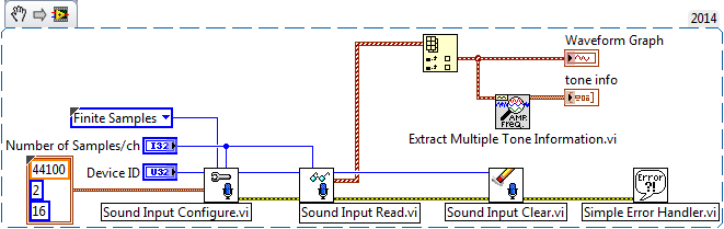
I have audio simple (level, THD, frequency) of the measures in LabVIEW with a sound card.
The audio signal is a sinusoidal 1 kHz analog single.
I know it's better to do it with a real audio Analyzer, but it would be a significant investment.
So, how can it be achieved with a standard of PC sound card? Thank you.I have a measurement of base (amplitude, frequency) with the following code:
-
frequency of measurement of digital random signal
Hi all.
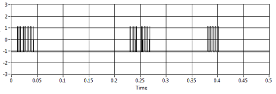
I want to measure the frequency of the signal. This value will be sent to any other device to vibrate the vibrator according to the value.
For example, I want to measure this signal:
I try to use your vi and extract single signal measure vi, but the result is not fair, for example, if I have no pulse on the graph the result is 11, 5 Hz (it should be 0 Hz)
I use assistant NI USB-6210 and acquisition of data to get the data from the sensor
Laughing out loud! All that motivates you... I don't see attachment. I commented on the block diagram on the vi attached which may help. What you can do in your data acquisition program, use is get the queue with the name of data. Then take the waveform of the DAQ assistant and use waveform components get to retrieve the values of the real signal (-1 to 1). Now use a loop with automatic indexing on table of signal and inside use enqueue to place each value of the signal on the data queue. In the joint programme filter, you can either copy the lower node in your program for the acquisition of data, or remove the loop of high signal generation and run them in parallel. The nice thing about the queues is that they can transport data between different vi on the same computer that the name is the same. If you want to do something with the frequency measures, while you can use a different queue for buffering of the data out of the loop of measure.
Good luck!
-
Different frequencies of signalexpress with oscilloscope
Hello
I'm new to the signal processing. I am facing some difficulties to measure the signal of a sensor of acoustic emission for my project. I use the PXI-6115 module with 1042 q and terminal block is TB2708. I used AI0 and AI1 for main signal and trigger respectively. I acquired the signal of 6115 in SignalExpress (v3.0) and convert to linear spectrum (Hanning window) and conversion of RMS with RMS on average 200. Same parameters are used in the oscilloscope (LeCroy LC564DL) too. I plugged the two signals of oscilloscope as well as for comparison. I saved data from the spectrum of SignalExpress and oscilloscope and plotted. You can see the graph as an attachment. It's totally different. Why is it so?
And one more thing, that is if I disconnect my connector NI DAQ system, spectrum in oscilloscope changed in amplitude at a certain frequency and vice versa.
Thank you in advance.
Myo
My apologies for the late reply. I've been sick for a few days.
I generated an amplitude 1V (2V peak-to-peak), 100 kHz, 10MS/s 20ksample sine wave to help to create an analog Signal. I treated it with the power spectrum using 200 linear medium with RMS algorithm. Value at 100 kHz - 3dB, as expected and as it should.
However, at a given time in the process, forced SignalExpress my frequency of 100 kHz to 50 kHz (probably due to a shift of frequency and the number of points). This would result in what you see. Check your project to see if this has happened to you. If so, you would get - 350dB to 100 kHz (essentially a pure signal noise floor) and - 3 dB to 50 kHz.
-
Sampling frequency for digital sampling (cDAQ-9172 & NI 9401)
Hello!
I have a cDAQ-9172 with NI 9401 C-series (digital) module. I would like to taste the digital inputs with a sampling frequency of e.g. 400 or 200 kHz. My problem is that I can only choose a clock 100kHzTimebase and therefore only get a sampling rate of 100 kHz. The 20MHzTimebase clock is too fast, as it gives me a sampling rate of 20 MHz). Is it possible to get a defined user e.g. 200 kHz sampling frequency, dividing for example down the clock of 20MHzTimebase?
Thank you! Last post and this article using the internal one or cDAQ chassis counters has solved my problem.
-
How can I quickly get its main value of amplitude and frequency of measurement of Spectra
See attached vi. Very well, the chart, I see that the dominant amplitude is 3 with dominant frequency of 100 Hz. But how to do that 3 and 100 of the value from the waveform data in a variable double?
I think I have the output waveform for measurement of the Spectra vi table and then do some math on it maybe high percentile or something, but that is awkward! Is there a special feature that can quickly the value of amplitude and dominant frequency?
O! blind me! Use max array and index. Solved already!

Maybe you are looking for
-
Impossible to reactivate XP Pro OEM after replaced motherboard
As the title says, I'm unable to reactivate a copy of XP Pro (OEM) after replacing a dead motherboard. I did have problems in the past when replacing hard drives. I reinstalled the operating system three times in the last 24 hours, does not. OEM dri
-
Can not install the printer due to the error this file contained a virus
I am running Windows Vista 64-bit and trying to install a HP Photosmart 3210xi printer. I get an error "AIO_CDB_Full_Network_enu_NB_exe" contained a virus and was deleted. Under Security Essentials, there is no virus and I need a way to solve this
-
GANYMEDE + and local access connection
Basic summary is that I want to have GANYMEDE + and local connection to access router on the vty lines. So, I did the two groups below. Goody obviously is what will use GANYMEDE and Console uses the local connections. I divide them between 0-4 and
-
Until leveled for Windows 8. Internet, CD and DVD does not work, it says that the drivers are up to date. Help.
-
Paste the symbol of Open Type fonts in postscript text
HelloI use a very old time police and paste into the regular times new Roman euro symbol in the text box. I would use the Open Type Times New Roman for the entire document, but reflow problems are large. My question, can I just after this symbol of t