Frequency rate real pulse readings
When I set up a counter to generate pulse train using 'DAQmx Create Channel (CO Pulse Freq)' and provide an arbitrary value at the entrance of the "frequency", I can read the value of the real rate?
SampClk.Rate on node DAQmx Timing property returns zero.
Too bad, it turns out that the FREQ counter. appears in the DAQmx Channel node. Go figure.
Tags: NI Hardware
Similar Questions
-
Change the Frame Rate, frequency rate not when shooting RAW
I think not all the controls to change the frame rate independent of the frequency rate that, I guess it's like 'project frame rate '.
How I crank out 240 fps 2 K RAW or say 60 fps (time base 23.98) during the filming of SXS?
Follow-up to question... is there a manual for this camera accessible to the public anywhere?
Thank you very much
BK
You can overcrank (once again, "S & Q" for "Slow and fast") to XAVC 1080 p at 60 fps at the moment, with firmware v1.10.
That's all. Any other framerate 60 fps have access by setting a frequency 59,94 system and slow down the images in the post.
-
Calculation of the frequency of real output of a PXI-5402
I have a card PXI-5402, sitting in a high chassis. I'm only interested in the sine wave output at frequencies up to about 10 kHz. I know that it is possible to request an output frequency and then interrogate the acutal output frequency but I prefer to be able to calculate before hand. All I can find in the literature is a figure of 0.355uHz for the frequency resolution.
Is there a better description of the frequency resolution? If this is not the case, the resolution is exactly 0.355uHz or is it an approximation (to 3 significant digits)?
This webcast is a great way to learn the process including the NI 5402 5406 OR exploit to generate periodic duty: http://www.ni.com/webcast/75/en/
The 0.355uHz value is a theoretical value of the frequency rate achievable depending on the size of the accumulator Phase and clock frequency. It's the closest thing I can find on ni.com that you can use to calculate the value: http://zone.ni.com/reference/en-XX/help/370524R-01/siggenhelp/ni_5401_11_31_frequency_resolution_and...
According to me, Fc for the NI 5402/5406 must be 100M and the size of the accumulator is 48 bits. Frequency resolution so = Fc / 2N = (100 × 10 ^ 6) / 2 ^ 48 = 3.55271368e - 7
Keep in mind that the device has a VCXO frequency accuracy specification of + / 25ppm, if you have no PLL block him to a better source.
-
VI to convert input signals NI 9402 in a RPM value, based on the frequency of the pulses
Hello
I'm looking for a VI convert an input signal NI 9402 in a RPM value, based on the frequency of the pulses. Is there such a thing that exists in the library of national instruments?
I run LAbview 2014 integrated control and monitoring on on a cRIO 9802 high performance integrated system with NEITHER 9402, 4 channels, 50 LV, LV TTL Module input/output digital, ultra high speed digital i/o for the cRIO module.
Any help would be greatly appreciated.
The easiest way is to use the FPGA to get the time between the edges of your pulse increase (shift registers to maintain the current situation and the time will be necessary). This will give you the period. If it's a single pulse per turn, then the number of laps is just 60/T, where T is the time in seconds.
-
rate real output analog OR-6351
Hello
I am trying to create a generator of arbitrary signals on both channels DAC on a NOR-6351.
Everything works fine - with the exception of the fact that I'm not sure what is the real rate of analog output.
This is quite crucial for me, I have calculate my wave based on Fourier transformation fast discrete - to get the correct frequency, so it is important to know the rate of real output.
The card has a rate of update AO 2.86MS / s,. The property timing - real sample clock frequency product also these 2.86 MHz.
When I then try to use the same frequency to generate two analog outputs, it always tells me that it uses 2, 86 MHz, even though the notebook loads says only he can produce 2 ms/s when using two channels.
So my question is, how to determine the actual flow of outputs analog?
And what is the rate of real output of the DAC?
Concerning
Jørgen
I just had a scope attached, while generating a sine function at 300 kHz, the rate of 2.86MS / s.
The scope read 300 kHz, which must mean that the DAC will actually to 2.86MS / s, otherwise the resulting waveform would have been to close to 200 kHz.
I have this will mark it as resolved, although I have not yet crazy understand why it is able to output at this frequency.
-
Hello
I have a power meter which provide the USB driver and a Labview program to get the data and NI USB-6221. The project I am currently working on the needs of:
1 acquire two signals (inputs of simple tension), pressure frequency KHz
2. acquire a flow signal, the output signal is 0 to 5V pulse, each pulse means 0.4 ml volume. So I use a voltage inflows to count impulses in certain period of time (in this case, 1 S) for water flow. ; KHz sampling frequency and the 1 Hz update rate
3. acquire a signal of engine speed. The output signal is pulse square wave whose frequency is related to the speed. I use a REIT port to measure the frequency. Sampling rate: Auto
4 give output voltage sine or square wave, I use AO do that.output rate: Auto
5 acquiring by VISA electricity meter data. Data update rate: every 50ms
Currently, all the 5 tasks work well separately. But when I put them together, some signals are beginning to hang, for example, pressure signals sometimes give nothing.
Another problem is the data record. I programmed the VI in such a way that whenever I press the button 'save start', he begins to record data and save them in a .cvs file. For some reason, I always get only the data in the first table. Coult someone help me? I download my code as follows
Hello
What I meant by open, write, close. For any type of file you are using.
Open the file, which produces a reference, then put the mention in a registry to offset.
Write data, using the function write (for this type of file) and the reference.
When you are finished, close the file reference.
Writing in the spreadsheet opens, written, close all at once. It is very good for this type of application.
***
The issue of the loop is more general. I would like to say first of all, I want to say that since each loop works on its own, it is own VI, and that this program has put all this into a single VI, which has a method to solve the problem is to disable all the loops and allow them one at a time to see if there is a culprit responsible for.
Using multiple loops executes the code at the same time, and some loops would be cycle faster than others, especially if some of them are loops just as they are.
Communication between the loops is a test to the address if necessary.
Running all these signals through different loops DAQ must also be examined. Don't know what questions are for read and write somewhat randomly in the channels.
-
sample rate real vs min sampling rate
I'm sure it's an obvious answer, but here goes.
I have a USB-5132 ' scope and using niScope horizontal configuration Timing.vi I put, among other things, the minimum sampling rate. In my case, I chose 20 MHz, which of course gives a sampling of 50 ns period.
I use niScope reading (poly) .vi with the WDT variant to read waveform data. I noticed something very strange - waveform limit testing throw error 1802 "signals have a dt of different values '-if I put a waveform components unclusterizer Get on the wire of waveform and looked at the value of dt of the wave." He told me that my dt is 40 ns, which of course is of 25 MHz. I also plead for only 2000 samples.
So what causes this shift? Why the digitizer does not accept everything just my desired sampling frequency?
Austin Walton wrote:
Andy,
The setting of minimum sampling frequency is the frequency at which digitized
the samples are stored, expressed in samples per second. This setting is rounded
up to and including the next legal collection that supports your device. Ownership of the actual sampling rate calculates the actual sample used for the acquisition rate.Unless you specify another source of the clock, the digitizer uses an internal oscillator as clock source. For the 5132, this oscillator is clocked at 50 Mhz. When using the oscillator internal as the sample, the digitizer clock source can use versions split to the bottom of this clock, for certain sampling frequencies are not possible.
-
Measure the frequency of the pulses PXI-6624
Hello. I work with a PXI-6624 and am interested to make measurements of pulsed frequency for frequency and duty cycle on its inputs using DAQmx.
When I go to create the virtual channel, however, I have error-200431:
"Physical channel selected does not support the type of measure required by the virtual channel you create."
' Asked the value: pulse frequency.
«You can select: frequency, period, pulse width, period of Semi, separation of the two edges, Position:...» »
Is this card really not capable of doing these measures of pulse frequency?
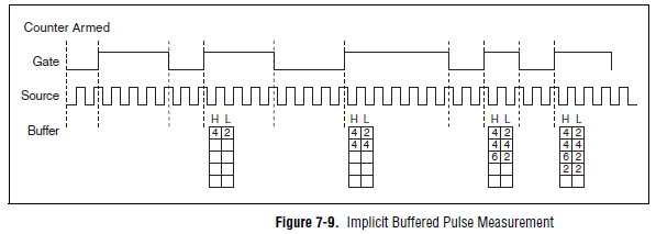
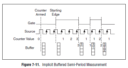
Yes, the "Pulse" (not to be confused with "Pulse Width") measure was introduced with STC3 of OR including CompactDAQ and X series devices.
Measuring the pulse:
However, you should always be able to measure the frequency and the duty cycle on your card with a half measure:
The half measure:
The images are in the X Series user manual.
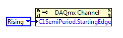
The difference between these two modes boils down to how the data is stored and implemented in buffer on the map - with the period semi method that the material does not distinguish between high and low samples and puts everything in a single buffer. However, if you start the meter on the song (see below the node property), then you would know the order of low and high samples in software, and are easy enough to calculate cycle frequency and the duty of this.
Best regards
-
Hi all
I searched the forum but have not found what I had, unfortunately I don't have time to read everything posted.
Basically I have a main VI that updates on every 200ms or so. This VI measures temperatures, control an analog output and measures analog voltage.
I need measure the frequency of two pulsed signals flow meter, 0 - 10V pulse square, frequency regularly goes all the way to zero (at this point I'm guessing that my max frequency would be approximately 100 Hz).
Using NI 9217, 9201 and 9263 modules on a 8 slots USB cDAQ.I think it means that I have not access to all counters. The 9201 measure also two additional tensions which do not need to submit to quick sampling at all.
A few questions:
-I guess I have to use two loops here, the main VI and the other, which must run faster, frequency measurement (or legumes)?
-J' found a VI that counts the pulses (attached), it changed a little to give me an average of impulse count per minute, but I don't know how to make it work in my VI,.
It wants to counter a table 1 d of waveform as its input, that I actually is a waveform out when you take the element of waveform Y
and that feeds the meter VI wacko values and depend on quick way the major updates of VI.
-If the main VI updates every 200ms label DAQ VI be in the fastest loop?
-J' tried to use the different waveform, impulse, period measurement VI but these all give an error at a frequency of 0 or 1 Hz
-J' used the measurement of timing and transition VI for that and wired the error to a structure of matter and made the "mistake out = true' empty case, it seems to work, but I think that there must be a better"
way than that. In addition, I need this signal averaged over a length of a few minutes.
I hope the above made sense. I'd be happy to try to clarify.
A hint in the right direction would be appreciated.
Thank you very much
Arne
I'll be back just from day celebrations. Thank you very much for your efforts. I'll try to incorporate this into my VI.
-
Hello
We need power RF amplifier with a function generator to create plasma in an ion source. The signal pulse duration must be 1ms long, repeated twice per second.
Today, we work in the following way: we spend the RF with f0 (aprox 1,995 MHz) frequency. After 20, we send a trigger signal passing frequency f1 (aprox 2.005 MHz). We keep this frequency for the rest of the pulse. However, the plasma that we generate is not 'constant' or stable during the whole impulse. If we smoothly change the frequency during the pulse we could improve.
We would like to do: use the frequency sweep: rather than use this frequency hopping, we would like to move smoothly f0 f1 (frequency scanning). Then F1 to f2.
As we have a PXI for data analysis, we believe using the arbitrary function generator of NOR: 5406 of NEITHER allowing the frequency sweep. However, in the book loads, it is not very clear, and I have a few questions:
-We can create a "list of frequencies. In the site OR below, it shows that the "minimum of Step' is 1.28us, which would be ok for us (I understand that the"minimum duration of Step"is the minimum time between 2 frequencies). However, the manual of the device "NI PXI/PCI-5402/5406 specifications" said the frequency list has a time step of 1 ms to 21s. What is the good?
-It is also said that the "duration of minimum list" is 1 s. For us, need us a shorter list that 0.5 seconds (we need to repeat the same pulse twice per second.). Is it possible to do what we want?
-At the end of the day, we would like to implement a control loop which modifies the list of frequencies in real-time.
http://zone.NI.com/reference/en-XX/help/370524L-01/nisignal_generators_help/features_by_device_smc/
Thanks for your help.
Best regards
Jose.Hi Jose,
You're right about the inconsistencies of the documentation. The minimum step was of 1 ms, but was changed to 1.28 µs to driver version 2.6. The help document has been modified to reflect that, but the specifications were not. I'll make sure that attaches.
The length of the minimum list is not listed in the book loads, and the latest version of the help the signal generators OR (driver version 2.9) lists the minimum list than the 1 step length. Aid has changed to the driver version 2.6.1 to clarify that the 1s meant 1 step. I've attached a screenshot of the help of the most recent.
There is an example that is installed with the NOR-FGEN driver called "Fgen Sweep Generator.vi". I would recommend from this for your application.
I hope that some of the inconsistencies in our documentation brightened. Please let us know if you have any other questions.
Elizabeth K.
Generators of signal produced technical support engineer
-
How to get the rate max one sampling NOR 9263 and other cards?
Hello!
I'm using a NI 9263 map and a chassis cDAQ-9172 proyect and im he 8.0 whit CVI programming. IM generating a sine and square waves to do some tests on a radio.
I want my program to be functional for all cards of this type, and we know that most of the cards have different specifications, for example sampling max tariff, in this case the Pentecost of work NI 9263 100 kech. / s as the maximum. IM generating waves based on the sampling frequency.
If my program must be compatible with most of the cards, my need to program to acquire max sampling rate using a specific function of NIDAQmx.h.
Do you know if theres a function or attribute that can return this value?
I tried this function with different attributes, with no results:
DAQmxGetTimingAttribute (taskHandle, DAQmx_SampQuant_SampPerChan, & MaxSamp);
DAQmxGetTimingAttribute (taskHandle, DAQmx_SampClk_Rate, & MaxSamp);
DAQmxGetTimingAttribute (taskHandle, DAQmx_SampQuant_SampPerChan, & MaxSamp);
DAQmxGetTimingAttribute (taskHandle, DAQmx_SampClk_TimebaseDiv, & MaxSamp);
DAQmxGetTimingAttribute (taskHandle, DAQmx_SampClk_Timebase_Rate, & MaxSamp);The three first atribbutes gives me the rate real samp which is 1Ks/s (according to me, is the rate of samp set to the default value for all cards you before be initialized for the user), but do not give me samp (100Ks/s) max flow.
The rest of the attributes only gives me the value of the clk, which is 20 MHz and the divisor of the clk (20000). Also I tried with a card 9264 (max samp rate is 25 ksps / s) and the function returns the same results.
Any idea?
Thank you!!
Hey Areg22,
I think I've found the service you're looking for:
http://zone.NI.com/reference/en-XX/help/370471W-01/mxcprop/func22c8/
This link gives just the syntax for the function, but the following gives you more information about the function:
http://zone.NI.com/reference/en-XX/help/370471W-01/mxcprop/attr22c8/
When I used the property of this function node output was 100,000 for the NI 9263. Which is consistent with the plug. I would like to know if it works for you.
Thank you
-KP
-
Create two independent signals and a pulse train with NI USB-6259
Hi all
I'm new to the forum, I searched but I've found no info about it.
I have recently set up a vi that is able to generate from an NI USB-6259 case two different signals in frequency, amplitude and phase (see attachment).
To do this with each cycle of the memory buffer size is changed accordingly for frequencies in order to see a whole number of periods and, thus, having not leak in the generation (or breaks).
Now, I would like to generate a pulse train at a frequency that is an integer multiple of the frequency of the input signal (not the 50 Hz one).
The resulting frequency of the pulse train could be changed on the fly (or at least be updated at each new round of vi).
I'm stuck because I have already said that two analog output channels and I want the pulse train so that a digital camera for my Board (channel PFI) output, you have any ideas?
Thank you very much
Alberto
PS. the vi is "program generazione.vi" but you must first install "signal.vi production".
Hello
It is a simple .vi which generates a configurable, buffered pulse train dynamically. I also want to let you know that with this type of advice (DAQ), it is impossible to update the output in real time. You must be careful because the time between you use "DAQmx Write" and the output effective physical change not IS NOT FIXED.Kind regards
Matteo
-
How to correct for IQ rates which are not supported by the NOR-2920?
Hi all;
I use Labview 11 and the NOR-2920 (Ettus Radio) to build a FSK receiver, I the Modulation toolkit.
My carrier is 169 MHz, my flow is 256Kbits/sec, my tour of frequency is around 89. 5 kHz, I choose a 16, my symbols FSK samples/symbol is 2 (0-1).
My receiver is close to work, however, I am getting an extra of 5 bits in my 408 bits frame data.
My sync bits are all the tail and the front end of my frame data which has also a meter 16-bit images on the front of the frame, which runs from 0 to 65535 without losing data.
I think that the extra bits are the result of rate IQ I try to set to 4096K based on 256 K * 16 = 4096 K
The radio seems to default to 4,166667 M for the rate of IQ.
The ratio of 408bits /415bits = 4096/4166 coincidence or not?
Is there a way around this problem in the configuration of the NOR-2920 or how I manage the sampling and recovery of data.
Any guidance would be greatly appreciated.
Don3of4
All interested for:
The answer is Labview a an I / Q resample module.
Connection between the extraction of radio and the demodulation modules, set the sampling frequency entry real want = rate * of the data samples / symbol.
Work so far, don't know what is happening when other tolerances overclocking begin to influence the data, but for now his work. Also don't know why this is not incorporated into the receiver or the fetch modules for sampling rate that you actually need from the beginning but I'm still learning.
Don3of4
-
How to increase frequency resolution in the power spectrum?
All,
I work on the analysis of data GET vi, and manage mucho when it comes to display a simple power spectrum which gives a precise simulation of sine wave frequency I use now. Most of the brain waves are between 1 to 50 Hz, and so I try to get a resolution of at least 1 Hz frequency. However, no matter what I do (increase the sampling frequency, use different sub vi and blocks), the chart plot only in frequency of 10 Hz increments. I know this must be a simple problem, but I can not find good documentation on this and would appreciate any advice anyone could give on this problem. I'm racking my brain here!
Nick
You need to acquire a second data to get the 1 Hz resolution. The increase in sampling rate only increases the bandwidth that covers the FFT.
Frequency resolution = 1/sampling
Scale of frequency rate of sampling/2 =
For your application, you will need to have a sample of at least 100 Hz rate. At this rate, you must purchase 100 samples to get the 1 Hz resolution. At the 1 kHz sampling rate, you will need to acquire 1000 points for the 1 Hz resolution.
-
PCI, I / AO at a different frequency
Hello
As a newbie, I met a problem when I tried at the entrance and the analog output signal at a different frequency.
I followed PID-control - Multichannel .vi to build a control program, so input/output can be synchronized. However, the project requires that the frequency of I be tenfold of the AO. I could re-write the while loop to make the output value constant for 9 of 10 cycles. However, in my view, it is simplest way to do.
Anyone provide an example?
Thank you in advance.
Sincerely yours
Ming
lmuri wrote:
Hello
As a newbie, I met a problem when I tried at the entrance and the analog output signal at a different frequency.
I followed PID-control - Multichannel .vi to build a control program, so input/output can be synchronized. However, the project requires that the frequency of I be tenfold of the AO. I could re-write the while loop to make the output value constant for 9 of 10 cycles. However, in my view, it is simplest way to do.
Anyone provide an example?
Thank you in advance.
Sincerely yours
Ming
Hello Ming!
Please use the Forums of NOR. You'll be happy to know DAQmx allows what I/O tasks such as these to be not run not only at the same time, but at different rates.
The problem with the solution that you have imagined is that this implementation will remove the delegation of tasks to the hardware level, and your program would become software-driven; This becomes a problem when you perform tasks of acquiring data at very high speeds as it becomes limited to the speed of your operating system (OS).
You can coordinate your tasks to operate synchronously and perform the output and the acquisition at different rates by creating a maintask. This means generally that you configure a task by DAQmx that keeps a clock frequency and you create tasks that use this clock frequency, or a division thereof, to exploit to their own individual frequency. This facilitated not only the execution of DAQmx tasks synchronous but also provide a material entirely focused on the solution of performance maximimse.
Thanks to LabVIEW, if you go to help > examples find to open the Finder of example of OR. If you are browsing material input and output > DAQmx > synchronization > multifunction > Multi - multifunction - Synch Dig read write with Counter.vi, you will find an example of how to set up a counter as a master of the task to control the operation of operation both a reading and writing . (This example shows a digital but implementation may be easily replaced by analog).
By setting the meter to the maximum frequency rate that you will require for your task (in this case, the speed at which you want to copy values) and apply it to the output of the SampleClocktask, you will drive the clock output task with the counter as the clock source. You can then use the meter as the source of the SampleClock for the task of entry, however to set the rate at any division of the driving frequency. In the case of your example, you can set the bit rate to 0.1 times the frequency counter to acquire a 10th of the rate.
If you want to acquire at the same rate, but only to retrieve values on the 10th of the speed, this same solution can be configured to produce instead a trigger to return an acquisition in the buffer. With a master synchronizing the task, the possibilities are endless!
I hope you find it useful, and if you need a precision more do not hesitate to let me know. Have fun with your DAQ!
Maybe you are looking for
-
Missing in SAFARI 10.0 default font size
Just updated to SAFARI 10.0, they removed the ability to change the default font size. Now, the writing is too small, what can I do to fix this?
-
I just downloaded firefox 5.0, which does not support the feature of best sites I've used so happily. Is there a similar add on that works with 5.0? I feel like I'm blind!
-
HP Mini 210-1076: BIOS configuration administrator password
I'm pulling my hair out on this one! I tried most of the codes listed on the forums and none work! I even removed and reset the hard drive and the NEED to enter the BIOS setup to verify. After 3 attempts I get "Disable System 66321791."
-
HP steam: strange files in "C:\system volume information.
I have re-installed Windows 8.1 on my HP net book successfully. I later discovered several large files in "C:\system volume information" with names that start with "{" and end by '} '. Are these relics of my re - install and can they be deleted safel
-
I have a boot sector virus (Troj/MBroot-H) that I can not remove from my computer without losing access to my HARD drive due to a custom boot partition. I can't afford to repair or replace the computer I have at the moment, so I try to disable thing