rate real output analog OR-6351
Hello
I am trying to create a generator of arbitrary signals on both channels DAC on a NOR-6351.
Everything works fine - with the exception of the fact that I'm not sure what is the real rate of analog output.
This is quite crucial for me, I have calculate my wave based on Fourier transformation fast discrete - to get the correct frequency, so it is important to know the rate of real output.
The card has a rate of update AO 2.86MS / s,. The property timing - real sample clock frequency product also these 2.86 MHz.
When I then try to use the same frequency to generate two analog outputs, it always tells me that it uses 2, 86 MHz, even though the notebook loads says only he can produce 2 ms/s when using two channels.
So my question is, how to determine the actual flow of outputs analog?
And what is the rate of real output of the DAC?
Concerning
Jørgen
I just had a scope attached, while generating a sine function at 300 kHz, the rate of 2.86MS / s.
The scope read 300 kHz, which must mean that the DAC will actually to 2.86MS / s, otherwise the resulting waveform would have been to close to 200 kHz.
I have this will mark it as resolved, although I have not yet crazy understand why it is able to output at this frequency.
Tags: NI Hardware
Similar Questions
-
Outputs analog USB-6211 won't go below 3.375V
I use a 6211 to pulse output 0 - 5V outputs analog using an external clock as a trigger, and after successfully using the system for a while I finished with a question where none of the channels AO out lower voltages at 3.375V. My current theory is that I can have exceeded the current 2mA max output, but I don't know how, which would result in what seems to be a permanent tension.
I have reset the device and tried using other computers, but the problem remains. I ran the diagnostic utility and it fails part AO when it tries to output 0V and reads the 3V but he gave no further information. All other parts of the diagnosis are very good.
Any help would be appreciated, I'm a little stuck on my diagnosis.
Hi Airgunner1,
I'm not quite sure because I've never worked this side of the process, but if you call in they should be able to tell what your options are. Sorry I can't be more helpful!
-
Producer consumer with inputs and outputs analog and digital
Hello world
I'm working on a program of control system for some practical test work. Currently, I am working on the data acquisition of the Labview program component. My architecture is consumer-product loops with a what. My system will have analog inputs, outputs, analog inputs and digital outputs. It is not a criticism of time sytem, but I wish that all the acquisition of data to synchronize. I enclose my program because it is at the moment. I have difficulties to get all the data in the since that I have two types of data. In addition, I don't know if I have synced the four sequences of read/write correctly. I would be very happy if someone could take a look at my program and give me some advice. Thanks in advance.
-
How to trigger and outputs analog and digital Outout tasks begins on a counter to start?
Hello
I'm trying to synchronize the start of a task outputs analog, a task of digital output and a task of counter. I want to start the counter to serve the master trigger and analog and digital tasks to synchronize his departure.
I guess I need something like:
analogOutputTask.Triggers.StartTrigger.ConfigureDigitalEdgeTrigger ("?", DigitalEdgeStartTriggerEdge.Rising);
digitalOutputTask.Triggers.StartTrigger.ConfigureDigitalEdgeTrigger ("?", DigitalEdgeStartTriggerEdge.Rising);
analogOutputTask.Start (); Slave 1
digitalOutputTask.Start (); slave 2
() counterTask.Start; n / / master
Where? is a string specifying a command source for the beginning of the task of the meter. However, I can't find what this string. Any suggestions?
Thank you!
-Jon
Just FYI, the solution to this problem as well as some other ones is encapsulated in a short example .NET, I created. It is on the Web site of EITHER:
http://decibel.NI.com/content/docs/doc-15500
This project shows how to synchronize all your analogue/digital outputs through tasks and forums in terms of synchronizing Calendar and start clock.
-Jon
-
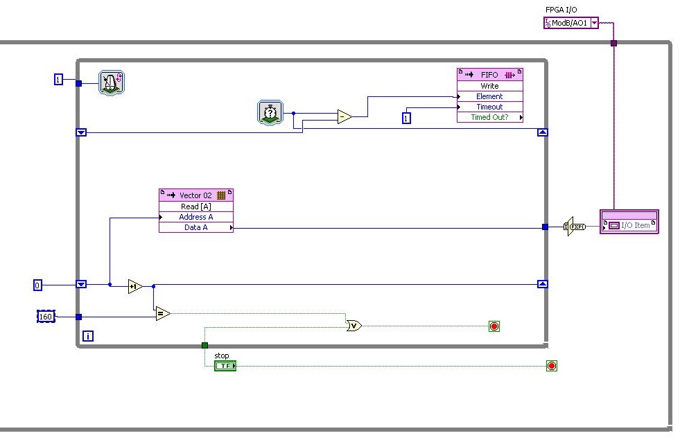
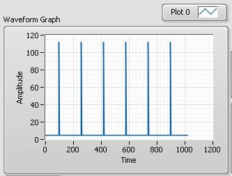
FPGA output analog fastest? (RIO 9641)
Hello world!
I read only analog output have about 38 tics. clock 40 MHz (RIO 9641)
My RIO gives me tics 107 = 112 - 5 analog outputs for the 1 iteration. If DAC cycle... The entire cycle takes (112 * 160 * 25th-9) for DAC 107 * 160 * 25th-9 = 428e-3 s always takes DAC, and I need more quickly.
How to set up outputs analog faster or rebuild program?I need the fastest analog output, is it possible?
Thanks for the help!
Hi togoto,.
Please let me know if I'm struggling to understand what you're trying to do, but the fastest, the analog output of the 9641 can update is 120 ticks by update. Which is based on the specification of the material on page 44 of the User Guide and the restriction that you touch. Therefore, I don't think you'll be able to get it down to 40 ticks.
-
Output analog, the USB-6009 case - can I use DAQmxWriteAnalogScalarF64?
I just got a NI USB-6009 and I try to use the outputs analog simple.
I'm running on a Mac, so I'll try to use the API OR-DAQmx Base 3.2 C (downloaded from here: http://joule.ni.com/nidu/cds/view/p/id/1078/lang/en). This is the most recent version of NOR-DAQmxBase, I could find.
I try to do continuous analog output on the 6009, which does not have a built-in clock. I was hoping to do the sync software and just new output values when I want to.
I can't get an output of database to work. Other messages and the example of Windows files, (e.g., National Instruments/NOR-DAQmx Base/examples/ao/MultVoltUpates-SWTimed.c) it seems that the best thing to do would be to use the DAQmxWriteAnalogScalarF64 function.
However, this is not in the Mac version of the C API of NIDAQmxBase. There is actually an entry for this in the NIDAQmxBase.h file, but it is commented out. Anyone know why? Is it possible to use this function for the analog output on request on Mac?
Thank you.
Clement
I have NEITHER-DAQmx Base installed 3.2 on a 10.4.11 system. One of the examples files 'genVoltage.c' calls DAQmxBaseWriteAnalogF64. I was able to compile and run this example with a USB-6009.
The DAQmxBaseWriteAnalogF64 function would work for you?
My guess is that, since you can write a scalar value with DAQmxBaseWriteAnalogF64, DAQmxBaseWriteAnalogScalarF64 becomes superfluous. The example provided with the installation shows how to write a unique value (i.e. scalar.). I pasted the code of OR below.
int main (int argc, char * argv [])
{
Task settings
Int32 error = 0;
TaskHandle taskHandle = 0;
char errBuff [2048] = {'\0'};
Channel settings
Char [] = "Dev1/ao0" chan
float64 min = 0.0;
float64 max = 5.0;
Sync settings
uInt64 samplesPerChan = 1;
Writing data parameters
float64 data = 3.25;
pointsWritten of Int32;
float64 timeout = 10.0;
DAQmxErrChk (DAQmxBaseCreateTask("",&taskHandle));
DAQmxErrChk (DAQmxBaseCreateAOVoltageChan(taskHandle,chan,"",min,max,DAQmx_Val_Volts,));
DAQmxErrChk (DAQmxBaseStartTask (taskHandle));
DAQmxErrChk (DAQmxBaseWriteAnalogF64(taskHandle,samplesPerChan,0,timeout,DAQmx_Val_GroupByChannel,&data,&pointsWritten,));
Error:
If (DAQmxFailed (error))
DAQmxBaseGetExtendedErrorInfo (errBuff, 2048);
If (taskHandle! = 0) {}
DAQmxBaseStopTask (taskHandle);
DAQmxBaseClearTask (taskHandle);
}
If (DAQmxFailed (error))
printf ("error in DAQmxBase: %s\n",errBuff); ")
return 0;
}
Hope this helps!
-
regeneration of the outputs analog
Hello
I am writing a program to fight mirrors laser. I use the example: output - analog continuous regeneration No. When I put a counter on since the while loop itteration, I can see I runs very fast for the first 10 hours, and then it slows down to normal pase... Is it possible to make the VI that it doen'st run so fast in the first round? Looks like that it is buffering a whole bunch of data... But I want to pause from time to time the exit...
Best regards
Thijs
-
Integrate the outputs analog with analog inputs
I have a program that displays 2 analog output waves and a separate program that captures the analog data through several materials of NEITHER. I need to integrate the program outputs analog in my analog input program.
The program of analog output is fixed as "AO_Triggers_LowLevel.vi" and the analog input is fixed as "ExperimentDAQ.vi". When I try and integrate these programs I get 'error-200560 occurred at DAQmx waiting until the Done.vi' to my function to wait until it makes my task of analog input (background of the program). I think it is my mistake in the order that I'm wiring to the top of my son of error but I'm not sure. I watched several tutorials (Timing and synchronization features of DAQmx) but I'm totally stuck.
Any suggestions are greatly appreciated. Thank you!
Alberto M.
I think I've fixed this problem. I extended my flat sequence structure to include the lines of task and error of my task outputs analog and things seem to work. I'm still not sure about what caused my error and why it has solved the problem...
-
How do I get the analog input signal and send it to output analog (real time)
Hello world
I do a simple task in Visual C++ and I use PCI-6221(37 pin).
Basically, I want to send the same signal of "analog input" to the "analog output".
at the same time (or almost), to make real-time application.
Can someone provide me with sample program please.
I would be grateful if you could provide me with the great tutorial that explains
step by step everything about NOR-DAQmx for C/C++ programming.
Best regards
Khassan
This is my code in C++, you can optimize it if that seems too messy. This code reads the analog input signals and exports it through the analog outputs.
To make this code additional work of the directories include and library directories must be added to OR.
I hope it helps someone.
#include
#include
#include "NIDAQmx.h".
#include#define DAQmxErrChk (functionCall) {if (DAQmxFailed (error = (functionCall))) {goto error ;}}
int main (int argc, char * argv [])
{
Int32 error = 0;
TaskHandle taskHandleRead = 0, taskHandleWrite = 0;
Read Int32 = 0;
float64 context [1000];
char errBuffRead [2048] = {'\0'};
char errBuffWrite [2048] = {'\0'};
bool32 done = 0;
Int32 wrote;DAQmxErrChk (DAQmxCreateTask("",&taskHandleRead));
DAQmxErrChk (DAQmxCreateAIVoltageChan(taskHandleRead,"Dev1/ai0","",DAQmx_Val_Cfg_Default,-10.0,10.0,DAQmx_Val_Volts,NULL));
DAQmxErrChk (DAQmxCfgSampClkTiming(taskHandleRead,"",100.0,DAQmx_Val_Rising,DAQmx_Val_ContSamps,0));
DAQmxErrChk (DAQmxCreateTask("",&taskHandleWrite));
DAQmxErrChk (DAQmxCreateAOVoltageChan(taskHandleWrite,"Dev1/ao0","",-10.0,10.0,DAQmx_Val_Volts,NULL));
DAQmxErrChk (DAQmxCfgSampClkTiming(taskHandleWrite,"ai/SampleClock",100.0,DAQmx_Val_Rising,DAQmx_Val_ContSamps,1000));DAQmxErrChk (DAQmxStartTask (taskHandleRead));
DAQmxErrChk (DAQmxStartTask (taskHandleWrite));While (! fact &! _kbhit())
{
DAQmxErrChk (DAQmxReadAnalogF64(taskHandleRead,1,10,DAQmx_Val_GroupByScanNumber,dataRead,1000,&read,));
DAQmxErrChk (DAQmxWriteAnalogF64(taskHandleWrite,read,0,10.0,DAQmx_Val_GroupByChannel,dataRead,&written,));
}
_getch();Error:
If (DAQmxFailed (error)){
DAQmxGetExtendedErrorInfo (errBuffRead, 2048);
DAQmxGetExtendedErrorInfo (errBuffWrite, 2048);
}
If (taskHandleRead! = 0){
DAQmxStopTask (taskHandleRead);
DAQmxClearTask (taskHandleRead);
}
If (taskHandleWrite! = 0){
DAQmxStopTask (taskHandleWrite);
DAQmxClearTask (taskHandleWrite);
}
If {(DAQmxFailed (error))
printf ("error DAQmx: %s\n",errBuffRead); ")
printf ("error DAQmx: %s\n",errBuffWrite); ")
}
printf ("end of the program, press the Enter key to quit\n");
GetChar ();
return 0;
} -
Fortunately the cRIO merger two time real screws: analog and digital output
Howdy,
I need help with a cRIO code. The purpose of the code is to acquire an analog input from the NI 9234 c series module and be able to send a "signal of pulse" digital camera (first low for some time, t1, then high for some time, t2) from a NI9401. Separately, I wrote the code to perform both tasks. However, when I add the code of RT digital output pulse pulses to analog input RT code, the DMA FIFO overflows because of the way that my digital pulse output code works. Currently, there are two reasons which overflows of the FIFO:
- The digital output code is pending for a while loop (pending "Send Pulse" become a true), the loop I can't empty the buffer FIFO
- The FIFO is not enough, quickly emptied depending on how long the pulse (t1 and t2) times are. The way I keep the pin high or low for a defined period of time is by issuing a sleep command, which blocks the loop I empty the FIFO. (Is there a "best" way to sleep?)
I have attached photos of my codes FPGA and RT. Please give me a suggestion on how to marry my two loops of RT for the use of happy resources! Thank you.
I found a quick way to solve this problem. I moved the timing of the Digital pulse on the FPGA. So whenever I have a Boolean value, the FPGA generates a waveform with the settings I put (a pulse in my case). This works because the FPGA loops run in parallel, I think. That's why, when I run a pending order in the loop of FPGA digital output, it does not prevent the FPGA of analog input loop to run. I have attached a picture of the code.
-
What is the minimum response of analog input, through DSP online, output analog time?
Hello experts!
I want to know if it is possible to get a very quick response latency (~ 1 ms) sound recording (analog input), through online registration (DSP online), the presentation of his (analog output) processing, by using the DAQmx programming codes. My system of NEITHER includes NOR SMU 8135, SMU 6358 DAQ Multifunction controller and SMU 5412 arbitrary signal generator. I also have access to the latest version of Labview (2015 Version) software.
My project is on auditory disturbances, which inovles record vocalizations, manipulating the recorded vocalziations and then present the manipulated vocalizations. My current idea of how to achieve this fact triggered output voltage after reading the input using DAQmx Read samples. DAQmx Read output is filtered online and then passed as input for the DAQmx writing for analog output. For purposes of illustration, examples of code are presented below. Note for simplisity, codes for the trigger part are not presented here. It's something to work in the future.
My question here is If the idea above should be reaching ~ 1ms delay? Or I have to rely on a totally different programming module, the FPGA? I am very new to Labview so as to NEITHER. After reading some documentation on FPGA, I realized that my current hardware is unable to do so because I do not have the FPGA signals processing equipment. Am I wrong?
Something might be important to mention, I'm tasting with network (approximately 16 microphones) microphones at very high sampling rate (250 kHz), which is technically very high speed. Natually, these records must be saved on hard drive. Here again, a single microphone is shown.
I have two concerns that my current approach could achieve my goal.
First, for the DAQmx Read function in step 2, I put the samples to be read as 1/10 of the sampling frequency. It's recommended by Labview and so necessary to avoid buffer overflow when a smaller number is used. However, my concern here associated with the latency of the answer is that it might already cause a delay of 100 ms response, i.e. the time to collect these samples before reading. Is this true?
Secondly, every interaction while the loop takes at least a few tens of milliseconds (~ 30 ms). He is originally a State 30 late?
Hey, I've never used or familiar with the hardware you have. So I can't help you there.
On the side of RT, again once I don't know about your hardware, but I used NOR myRIO 1900, where he has a personality of high specific speed for the RT where I can acquire the kHz Audio @44 and process data. Based image processing is ultimately do the treatment on a wide range of audio data you have gathered through high sampling frequency and number number of samples as permitted by latency, please check this .
I lost about 2 weeks to understand host-side does not work and another 2 weeks to understand the even side of RT does not work for online processing (real time). Then, finally now I'm working on FPGA, where the sampling rate is 250 kHz (of course shared by multiple channels).
The complex thing with FPGA is coding, please check if the filter you want is given below as labview automatically generates some codes of some filters.
Most of them will work in 1 SCTL IE if your target has 40 MHz clock algorithm will run in 25 ns. That's what I was looking for, I hope you

See you soon... !
-
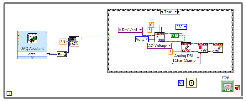
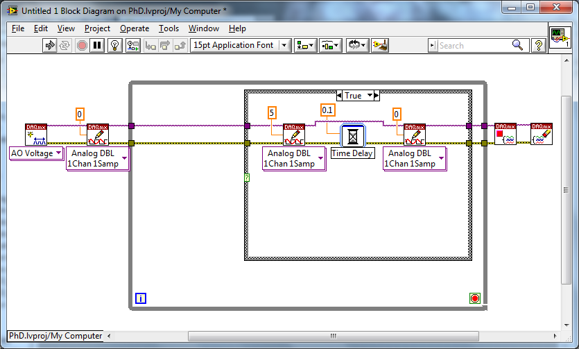
Output analog single shot: how this impulse. Probably easy, I am at a loss.
Hello.
I have a piece of equipment connected to my system. Whenever it reaches a proximity sensor (it is a reciprocating machine), I need to make a single pulse of 5v out of my analog output. It must be fast, it should stop until the sensor is reached again, and he can't stay 'market' for a long time.
I have attached my VI. I use a power supply via the DAQ assistant, routed via a logic to produce a Boolean 'true' value whenever the sensor is reached and that boolean is connected to a structure dealing with tasks created in DAQmx voltage.
My problem is that the machine will not reverse while the case is always true, and there is still the 5v called by the real case on the structure of the case. Pulse, and then stop, be allowed to return when the proximity sensor is again reached. As it is now, the machine reaches the prox and then the whole system stops, as the condition of 'real' on the case structure and the subsequent voltage output, remain high.
I have attached the VI and the hierarchy as well.
I tried a few different things here, as everything using a DAQ assistant with samples of N, but that would be just retrigger when the loop repeats itself in any case.
I'd love to sit and bang my head against this until I understand, but I am under a time constraint. Help!
Try something like that. Set the input to the function of "Delay" for however long you want your pulse to be (within reasonable limits). You have not specified a value of "fast". I initialize your line of analog output 0... It's a good idea, but it's up to you if you want to do it or not.
-
Synchronization output analog and an entry for imaging
Hi all
I'm stuck in my higher studies project and really need help. I tested an imaging system, where one uses two mirrors MEMS to analyze the sample and a tube set (PMT) allows to acquire voltage signals and translate them into images of scanning laser.
I use the same DAQ card for input and analog output. The DAQ card sends features X and Y of the MEMS mirrors so that the reason for scanning 2D starts left to right and up and down.
Scanning rate: 131500 pixels per second.
Size: 1170 by line, 514 ranks in total pixels.
Thus, the mirror will scan 601 380 pixels per image, which takes approximately 4.57 seconds to complete. I almost finished this part in LABVIEW.
However, only a part of the scanned pixels are read by the PMT. We want to get an image of 512 x 512 pixels. For example, the PMT works like this:
(1) the sampling rate is also 131500.
(2) skip the first row.
(3) starting at the second row, the PMT will jump the first 329 pixels, read in the next 512 pixels and skip the rest 329 pixels again. Then, it moves to the next line.
(4) jump the last row.
My approach in the plate sequence
(1) ignore the signals of all 841 (1170-329 = 841).
(2) create a loop for, run 512 times.
(3) in each loop, first jumping 658 signals (329 x 2), then read the signals then 512 MB.
(4) wait 1499 pixels left to complete the digitization (1170 + 329).
Problem
The mirror and PMT must start and finish at the same time running. However, when I run my VI for the analog input and create the image on the Panel, it takes 5.7 seconds to complete, which means that they are not at all synchronize. It seems that there is some unexpected time in the loop for, but I don't know how to change the code to meet the requirement of calendar.
Please see the attached VI. Any help is greatly appreciated.
~ Sheng
My approach in the plate sequence
(1) ignore the signals of all 841 (1170-329 = 841).
(2) create a loop for, run 512 times.
(3) in each loop, first jumping 658 signals (329 x 2), then read the signals then 512 MB.
(4) wait 1499 pixels left to complete the digitization (1170 + 329).
Consider this: add up all these pixels, both those you want to record and those you want to ignore.
If I read you right, that would be:
841 + 512 * (658 + 512) + 1499
Regardless of this number, set up a task that many samples and record the whole bloody thing. Let the time of equipment for you.
Then, AFTER that data are in hand, pass by and throw the first 841 points, then for each loop, throw away 658 and keep 512... etc.
IOW, let the MATERIAL which made the better material: precise timing.
Let the SOFTWARE do what does best software: weird logic.
-
To write a waveform to two outputs analog of DAQ(USB-6215)
Hello
I use USB-6215, who has two analog outputs and having to send the same waveform through the analog outputs two of my DAQ. at the same time. in fact, I have a text file consisting of a code word (please see the attatchment) with dt, freq and annex 0 in the first column and other columns contain the word coded. Withe the help of dt, the rate and the data I did a waveform with the wave of construction VI. I am able to write this wavefrom through an analog output A01 right now. I want to know how I could write the same analog waveform other AO0 out simultaneously. I use a source of external triggering via PFI0 to be triggered. for now, I use the write.vi DAQmx (analog channel 1 DBL 1 d N samples) and DAQmx create virtual channel.vi with dev1/ao1 as the physical channel. For more information, I am attatching the program along with the text file. Please see page 2 of my structure of matter in the VI attatched.
Thank you.
Kind regards
Raja
Hi Steve,.
his works now. I changed the instance of writing DAQmx for analog waveform samples N channel N. still, I now that a single waveform. How could I do like two like it (writing DAQmx) will not accept a single waveform as the entry as the number of channels in the task will now be 2 where, under the waveform has an exit.
Kind regards
Raja
-
Tecra S3 Advanced Port Replicator III more: video output, analog & digital
I have a Tecra S3 in association with Advanced Port Replicator III.
I can't get the two graphics cards to work together.The analog and digital video output should work together.
It works on a Tecra S2, but not on the S3?
Does anyone have an answer?Hello
You want to use both outputs DVI and VGA on Advanced Port Replicator III graphics more simultaneously?
Advanced Port Replicator III more supports the use only if the computer system unit laptop itself also supports the simultaneous use of RGB & DVI.
So that would mean that the backs of Tecra S3 not supported this feature


Maybe you are looking for
-
Satellite M70-144 buttons of media?
Hello fellow forum members: xI just installed * Windows7 * on my laptop, it's an almost 4 years * Satellite M70-144 * (PSM71E-01400LED).I don't know how to make my built in media player buttons. I don't see any missing hardware driver, but still noth
-
Satellite A200 - 1 M 8 - whistle problem
Hello.. I have the computer model toshiba laptop: Satellite A200 - 1 m 8 OS: Win XP SP3 I don't know, but sometimes something in my laptop randomly and suddenly made like noise or whistle, but NOT clicks when your hard drive is going to die. It's exa
-
My EliteBook 2760p had a hard drive failure and now, after replacing, it works a lot slower
Good afternoon! I have a serious problem with my EliteBook 2760p!About two months ago, my EliteBook had a disk failure hard and after more than two weeks of control and test.the hard drive has been replaced, and I received my EliteBook return.I immed
-
Installation of the updates. Updates for Windows 8 mess up my Vista.
Try to make a backup disk
-
Envy 17 t-3200: temperature of the system (90 d)
OS: Dual Boot Windows 7\Windows 8.1 BIOS: Insyde F.0B, 02/01/2013 CPU: Intel (r) Core i7-3820QM CPU @ 2.70 GHz Graphics1: Intel(r) HD Graphics 4000 Graphics2: Radeon (TM) HD 7850 M Normally I turned off the laptop by selecting 'Sleep '. So I reboot r