low 0 Hz pulse frequency
Hi all
I searched the forum but have not found what I had, unfortunately I don't have time to read everything posted.
Basically I have a main VI that updates on every 200ms or so. This VI measures temperatures, control an analog output and measures analog voltage.
I need measure the frequency of two pulsed signals flow meter, 0 - 10V pulse square, frequency regularly goes all the way to zero (at this point I'm guessing that my max frequency would be approximately 100 Hz).
Using NI 9217, 9201 and 9263 modules on a 8 slots USB cDAQ.I think it means that I have not access to all counters. The 9201 measure also two additional tensions which do not need to submit to quick sampling at all.
A few questions:
-I guess I have to use two loops here, the main VI and the other, which must run faster, frequency measurement (or legumes)?
-J' found a VI that counts the pulses (attached), it changed a little to give me an average of impulse count per minute, but I don't know how to make it work in my VI,.
It wants to counter a table 1 d of waveform as its input, that I actually is a waveform out when you take the element of waveform Y
and that feeds the meter VI wacko values and depend on quick way the major updates of VI.
-If the main VI updates every 200ms label DAQ VI be in the fastest loop?
-J' tried to use the different waveform, impulse, period measurement VI but these all give an error at a frequency of 0 or 1 Hz
-J' used the measurement of timing and transition VI for that and wired the error to a structure of matter and made the "mistake out = true' empty case, it seems to work, but I think that there must be a better"
way than that. In addition, I need this signal averaged over a length of a few minutes.
I hope the above made sense. I'd be happy to try to clarify.
A hint in the right direction would be appreciated.
Thank you very much
Arne
I'll be back just from day celebrations. Thank you very much for your efforts. I'll try to incorporate this into my VI.
Tags: NI Hardware
Similar Questions
-
PXI-6133 Pulse frequency output and input with DAQmx
I am trying to set a pulse meter output frequency task and read this signal with a frequency counter input task input pulses. I use a 2 PXI-6133, each connected to a BNC-2090 case has. I want to output a square of a certain frequency with the task frequency meter pulse output and then read the frequency of this signal using a task of cost input frequency. I don't know how to property set up these tasks, or how to define which device to use for each heap. I don't know what terminals on the BNC-2090 is the counter of entry/sortient channels correspond to them because that is not displayed in the documentation of the PXI-6133 or documentation of BNC-2090.
Please see the attached VI for my attempt to put this in place. Currently, I get two errors:
(1) error-200452 took place at the property Node DAQmx channel meter Test - referred to as property is not supported by the device or is not applicable to the task.
2. the error-89136 at DAQmx Start Task - specified route cannot be met because the hardware does not support.
If I remove two channels of property DAQmx where I try to put the terminals for the counters, while the program is running, but then I know not what terminals on the BNC-2090 meters are connected to! This causes the DAQmx read for the cost in the tasks of frequency to timeout because it does not detect a signal.
I would really appreciate the help to properly configure these tasks and determine what terminals on the BNC-2090 case has the task of counter will work on.
I see a few problems in the code originally:
- For your CI task, you type is defined as a counter entry > frequency. But on the node property of DAQmx channel for this task, you modify the CI. Property of PulseWidth.Term. It should be CI. Freq.Term. set the entry regardless of the PFI line you do not want the input signal on. Tip: you don't have to type the name of the device in at all. Enter "PFI0", it's the same as "DevN/PFI0" since the unit has already been specified in the DAQmx Virtual Channel Create function. The name of the device, leaving aside will make your code more flexible where you decide later to change the name of the device.
- Maps of the S series, such as the 6133, do not have the same flexibility to change the output terminals of tasks of meter you might find with M or X series device. Page 83 of the S series manual watch what signals can be extracted to PFI lines - Ctr0Out is not one of these. Instead, Ctr0 out is, by default, pin 2. Cabling to a BNC-2090 6133 is certainly difficult to understand out (probably because the 2090 was designed to work with the materials of the E and M series), but if you compare the pinout of a PXI-6255 0 with the 6133 pinout connector, you will notice that they are essentially a match 1-1. Pin 2 is PFI12 on the 6255, so I assume the same for the 6133. All this to say, Ctr0Out always appears on the pin 2/PFI12 for the 6133 and you therefore cannot change the output terminal that your code is trying to do, having for result error-89136. Remove this node from the property altogether and the error should disappear.
-
Pulse frequency of CO generates actually 1 pulse per second?
Hi all
I have a VI installed outside in the attachment below. I seem to have a lack of understanding on how to program this VI here. I do not understand what might not.
The VI is very basic. The frequency has been set to 1, and the units are Hertz. For me, this means that the application must send a pulse to my linear actuator ONCE per second. I have a simple Pulse counter set up in VI so count the number of pulses is actually sent (using the DAQ assistant). Why is that when I run the program, I get around 300 pulses per second? Elevate the value makes it goes a little faster, but the value isn't really do go more slowly. It seems no real correlation between the input frequency and the number of pulses that are sent.
I just want a program that I can enter "1 pulse per second" or however many impulses I want per second and have the card send a pulse per second (or however much is entered). Where should I start? I have an entire program written and ready to go, but this concept of base here escapes me completely.
Thank you
James
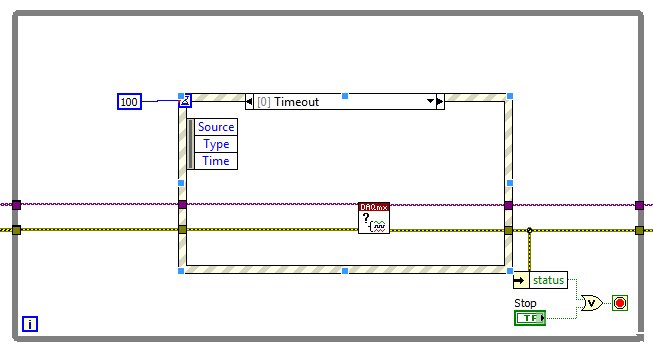
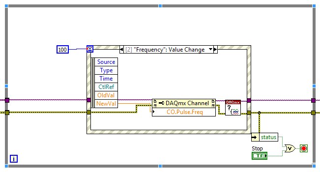
Attached: photo 1) of the concept that I am completely baffled on 2) VI of my program that says the concept is used in
In the simple image, you run a loop as soon as possible (it has no timer mechanism). Inside this loop, you configure the task of the pulse, run it, then immediately stop and disable. You need to create the channel and configure the synchronization outside the while loop before it starts, and you need to clear the task outside of the loop this way, after the while loop ends. Depending on what you want to do, you should be able to move the beginning of the task outside of the loop this way, or simply let the task automatic start.
You will need to restructure your VI a little. I can't tell if you want to delete the task after each step, or simply change the frequency. If it is just the frequency, you can use DAQmx write to change; If you need start and stop the task, you will need logic to do once whenever you want to start (you can get an error if you start a task that is already running). There is no need of "Is the task performed?" since you do not use the exit for what it is.
EDIT: Also, it's always a good idea to put a waiting inside loops that run indefinitely. Otherwise, they will turn as soon as possible, all processors available time and prevent any other code to run. If you configure your task to meter correctly the time loop will not affect the value of the pulse (because it is done in hardware), but there is no need to run the quick loop.
-
Sync to external trigger in conjunction with a nearest pulse frequency device fixed...
I am writing an application running a scan frame. One axis of the scanner runs at a fixed frequency. I use a scanner high speed 5105 to get the data. The slow axis of the scanner is controlled by a servo with an analog input. I have will probably use an M-series card for analog control, but can also go with a 6713 (output only) or another Board. Fixed frequency Analyzer provides a clock line, I want to use to drive the 5105. In addition, the analog card must be synchronized in this. The entire system should be able to accept a trigger external devices, as it starts scanning at the edge of clock on next line.
I'm not quite sure about what would be the best way to do it. External triggering from other devices will be an indeterminate pulse width, so I can not just use it as a portal for the line clock. I am reluctant to do it in software (IE via the detection of changes on a digital line) because I want to be reliable started the next clock pulse. I have taken into account things like a counter/timer with a relaxing break, but which could lead to drift between the narcotics control and frequency scanner fixed. It seems just more complex that I think it should be, and it feels like I'm missing a simple way to do it.
Any suggestions?
Hi cshl,.
Good to know - the 5105 has a duty cycle of tolerance of 45-55% (mentioned on the page of the form), so that is why you cannot change clock speed from 3 to 12 MHz on-the-fly (though if you make small incremental updates over time, it would be theoretically possible).
With the additional information in mind, you might want to try the following on the 5105:
Use the external trigger as a trigger of departure (arm of acquisition).
Use the line as a signal reference clock (with a position of 0 samples for reference ~ 7500 are after initiation).
The problem with this is that you will have to re - trigger on each line - 5105 has a 2.4 rearm us time (also mentioned in the page on record). If this is unacceptable, another way that I can think of is to use a clock to external reference in PLL internal clocks of the bezel to. If you can provide a stable, a clock accuracy 50 ppm which is synchronized with your scanner within reach, would solve the problem of drift over time without having to re - trigger on each line (only acquire data continuously). This clock frequency must be between 1 MHz and 20 MHz in steps of 1 MHz.
We have no Council can take in an external variable clock up to 12 MHz (on-the-fly), but if you wanted to compromise a little bit the 6115 can enjoy up to 10 MHz, and has no obligation to cycle to 45-55% so it's maybe interesting look in.
As far as AO goes, I assumed that the clock line is declared after the quick scanner has completed his turnaround (ideally you do not update the zone of OCCUPATION during the lead time). If you have a signal Analyzer that you can use instead probably easier. If not, our peripheral series M and X series (but not the series AO 67xx) offer reference clock feature so if you go with the idea of reference mentioned above clock it may be easier to simply PLL the clocks together. These cards in a PXI chassis or are they PCI form factor?
I don't know what you mean by the sticking point about the need for two triggers. I think the idea is that we use the external trigger to arm the 5105 and clock line to trigger each record. However, if you do not need to generate a pulse double based on the clock of your line then you can use counters to do (our counters are redeclenchables with time to rearm in the ns range).
Best regards
John
-
Measure Z to a battery encoder encoder pulse frequency to measure the speed using a 6034 E card
Hello
I want to measure the speed of a motor that has an encoder to encoder hung on battery. It provides impulses 3 A, B and Z I uses a PXI 6034 E card. I wanted to know if there are any examples/ideas that could help me with this (I'm new to digital programming in Labview). I moved to NI Daqmx 9.8 recently of the old version that has supported the existing codes and therefore being updated the code. I also want to know if an external clock source is needed to do this. This.
Hello
There are several examples in the finder OR example (you can get here by going to help > find examples in a window of LabVIEW). You can browse examples of Encoder on input and output material > DAQmx > entry counter. You should be able to find some examples that will be useful.
In addition, this link is a good resource to get started using DAQmx: http://www.ni.com/white-paper/5438/en
Thank you!
-
Measure the frequency of the pulses PXI-6624
Hello. I work with a PXI-6624 and am interested to make measurements of pulsed frequency for frequency and duty cycle on its inputs using DAQmx.
When I go to create the virtual channel, however, I have error-200431:
"Physical channel selected does not support the type of measure required by the virtual channel you create."
' Asked the value: pulse frequency.
«You can select: frequency, period, pulse width, period of Semi, separation of the two edges, Position:...» »
Is this card really not capable of doing these measures of pulse frequency?
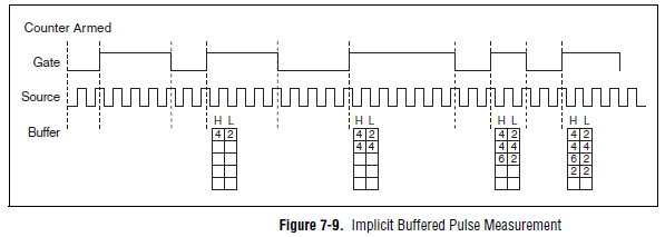
Yes, the "Pulse" (not to be confused with "Pulse Width") measure was introduced with STC3 of OR including CompactDAQ and X series devices.
Measuring the pulse:
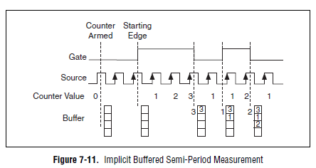
However, you should always be able to measure the frequency and the duty cycle on your card with a half measure:
The half measure:
The images are in the X Series user manual.
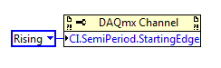
The difference between these two modes boils down to how the data is stored and implemented in buffer on the map - with the period semi method that the material does not distinguish between high and low samples and puts everything in a single buffer. However, if you start the meter on the song (see below the node property), then you would know the order of low and high samples in software, and are easy enough to calculate cycle frequency and the duty of this.
Best regards
-
How to generate a variable frequency pulse train constantly
Hi all
I am using NOR-USB-6259 (BNC) to send signals of impulse to the position of a servo with labview motor control. The position of the servo-motor control follows these rules:
- The pulse train number determines how many degrees the motor;(par exemple la position angulaire dele de moteur)
- The pulse frequency determines how fast the engine is running; (for example the engine rotation speed)
- Digital determines the direction of rotation of the engine (for example in the clockwise or counterclockwise)
My question is when I have to continuously generate a body finished, train signal in a period of time. Here's a sample:
Time (s)
Number of pulses
Direction of rotation
(1 clockwise, counterclockwise 0)
Frequency
0-1
923
1
923hz
1-2
3540
0
3540hz
2-3
1751
1
1751hz
3-4
2663
0
2663hz
4-5
353
0
353hz
5-6
1017
1
1017hz
6-7
3436
1
3436hz
7-8
10 p
0
302hz
8-9
1513
1
1513hz
9-10
570
1
570hz
Here is the explanation of this table, the motor continues to turn clockwise for 0 ~ 1s. When the time reaches 1 s, the engine simply fill out the rotation of 923 pulse signals. And then the engine starts to turn clockwise for 1 sec ~ 2 s. When the time reaches 2 s, the engine simply fill out the rotation of 3540 pulse signals. So we can see that the speed of rotation of the motor to 0 ~ 1 s is different from the speed in 1 ~ 2 s. Namely, the frequency of the signal from pulse to 0 ~ 1 s is different from the frequency in 1 ~ 2 s.
I already use the DAQmx counter output, it can simply generate pulse signal with some numbers and some frequency only once. The attachment is the vi that allows to generate a digital pulse train finished the meter output channel and frequency, cyclical, delay report Initial and idle state are all configurable.
How can I continuously generate a series of pulse train with a variable number and frequency for a certain period of time.
Thank you very much for your help!
The frequency 'on the fly' control requires intervention of software and can not guarantee a specific number of impulses for each rate (which I assume you want because it's an engine step by step).
If it was me I would do one of them instead:
1. use the digital output for everything. The digital output at a higher clock rate and build the waveform to give you the desired number of steps and management. This method would give less temporal resolution than others.
2. use a task of meter output, 1 section at a time. Reconfigure and restart the task for each section after the management output setting. This method could introduce a delay between each section.
3. purchase of new equipment - X series supports put buffered outputs of meter that can do what you ask.
Best regards
-
CAN´t set up a low-pass filter properly
Hello everyone,
First of all, sorry for my bad English!
Before asking this question, I ve tried to seek answers in the forum and couldn t find a useful for my case.
I m new to LabView and I m test for the analysis of the signals. I m using an Agilent signal generator and a NI USB 4431 to acquire the signal.
OK, here´s my problem. I can´t use of a Butterworth or a Chebyshev filter (or any type) to create a low-pass filter filter. I Don t know if I didn t understand it s parameters correctly or if I m set something wrong. When I use the ExpressVI filter, I get the result I want to, but when I use the function of Butterworth, it doesn´t work.
Can someone help me please?
I m sending the project I ve designed, so that you guys can see what I ve done.
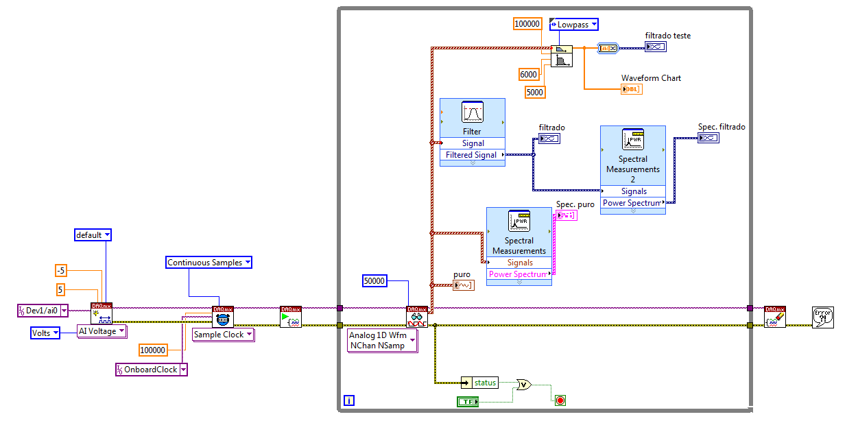
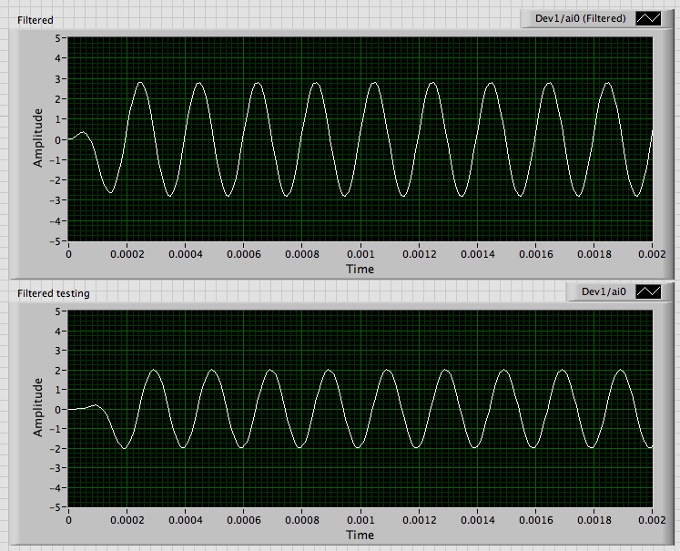
Here some explanations: the "puro" labeled graph is the pure I m signal generation.
The labeled graph "Spec. PURO"is the power spectrum of the signal current
The graph "filtrado" is the signal after going through a low pass filter in the express VI (which works fine) and the graphic "filtrado Spec" is the power of it s spectrum.
In the upper part of the loop is the function of Butterworth filter. I ve wired the pure data to its input signal and expect one out everything as the express VI creates, but he's not even conspire anything in the chart.
The windowed FIR filter VI generates the error-20023, which constitutes a violation of Nyquist. Because this VI returns only an error code and not the cluster of standard error, you must connect explicitly an indicator or manipulation to the error output.
The cause is that you have the frequency to zero. OR use a somewhat confusing nomenclature for the inputs of the filter frequency screw these detailed help says:
high cut-off frequency: fh is the high frequency in Hz. The default value is 0.45 Hz. The VI ignores this parameter when the type of filter (low pass) 0 or 1 (high-pass). When the filter type is 2 (bandpass) or 3 (Bandstop), high cut-off frequency: fh must be superior to low cut-off frequency: fl and respect theNyquist criterion.
Thus, for the high pass filters and both low-pass cut-off frequency is the value wired to low cut-off frequency: fl. I regularly get this error. When I get strange results, I read the help and fix it. As soon as I wired 5000 to fl, the output looks like this:
The differences in amplitude and transitory initial are likely due to different specifications of filter.
The way I start it is to convert the flag to a Pure control, do default to the current value, and then put all the DAQmx screws in schema structures disable. I have disable placing the pure control (or a copy of it) in a case to permit the schema structure which has the DAQmx Read. Since you have only one data channel I added the Index table to get a unique waveform of the table. Then all the code signal analysis works.
Lynn
-
6218 USB voltage and pulse acquisition
I use the USB-6218 to run 2 OR task at the same time in my vi. A task is to acquire a pressure transducer voltage and scaling it. The other task is the counting of pulse frequency with a flow meter and scale. Both tasks will work perfectly when I run them in Max, or run individually in my vi as a sub - vi. But when I try to run at the same time as I get wrong the meter reading of. It seems that the meter is losing his job after its first reading. Each task is written in its own subvi who takes a sample, and I'm sure that the task has stopped before that starts the other task. I don't get any errors, but I have to stop and restart the computer to clear the task of counter before he can start to read correctly.
Hello joe_n1,
It seems that this question is because of the way you use your tasks in subVIs. If you create a task and then delete it each time, then every time that the task starts off fees. As you say, he will lose his job after the first reading.
To avoid this problem, make sure that you are only to create the task (usually at the beginning of your VI) once and then once compensation (usually at the end of your VI). Really, the only thing you have to repeat is the actual readings DAQmx. For this reason, I would not recommend putting your tasks in subVIs. You shouldn't have to stop each task before the other begins - rather, you should be able to run them simultaneously.
-
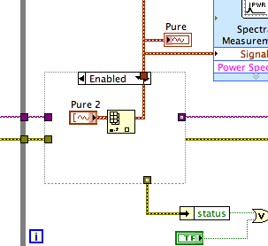
DAQmx property in event node can % 27T be update
I want to update the node property of DAQmx event to update dynamically the value, but only 1 of the 2 property node can be updated "DAQmx is task Done.vi", the whole could be triged normally.
As shown in the photo below: report cyclic case can be triged and run, but the value of property not upgrade vi DAQmx. well frequency one normally.
The answer is probably more strange than you expect. It turns out that the two impulses of the synchronization frequency and duty cycle parameters are also privileged. (I believe that the same kind of asymmetry applies when you set a pulse with high and low time).
Frequency Gets the privilege in this sense the pulses of timing is changed only when a frequency value is written. In order to change the operating factor, you need to get a property node DAQmx Channel, expose the properties of duty cycle and frequency and write to both of them. You don't need to change the * value * you write in the property of frequency, but you * need to write for her. Given that written node property follow these up and down, it is important to have the property of cyclical report above the frequency property.
Here is a more complete article.
-Kevin P
-
Problem in reading the PWM signals in myRIO 1900
Hi guys,.
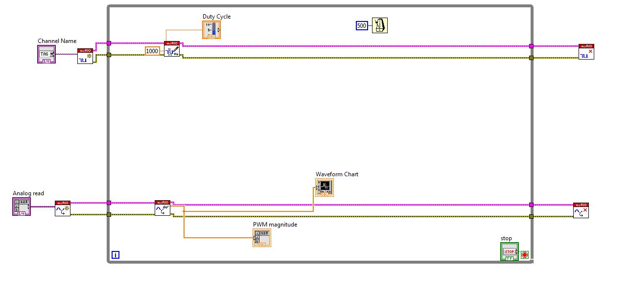
I work with myRIO to generate PWM pulses.
Here is the block diagram of my circuit.
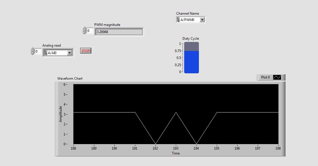
I connected external to the analog input pin PWM pin. So I can watch the PWM pulse in the waveform table.
But the waveform is not clear. This is as shown in the screenshot.
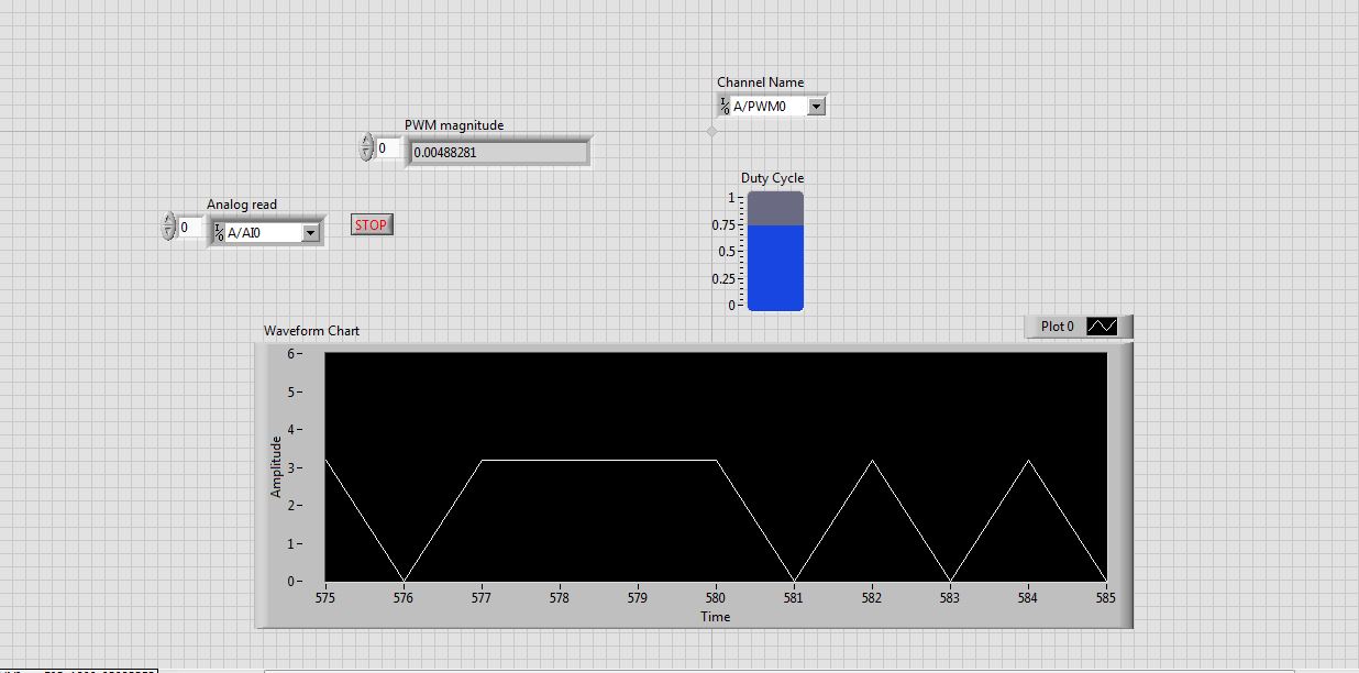
See that the waveform is not correct. When I'm watching the same PWM pulses in the CRO (cathode ray Oscilloscope, oscilloscope real in the real world), I get exactly the waveform. that is, the PWM pulses are generated correctly. But the analog read is unable to read the PWM pulses.
I faced the same problem with the pin of analog reading earlier when I read the input voltage. Is not give continuous reading of the voltage input.
Please guide me how to read these impulses via analog read.
Please tell me at what frequency range, I can use this myRIO to generate impulses?
I am able to use 40 kHz?
Hi rcs.
The desired pulse frequency is 10 KHz. My sampling rate must therefore 100 kHz, which is not possible in data acquisition mode. There is another problem with the myRIO. Only AI0, BI0 and CI0 has n-sample mode. The analog input pins is still have no n-sample mode. But in my project, I need 4 pins of I in n-sample mode, which is not possible. In addition, the sampling rate should also be favourable, which does not happen in my case. We can say that this is a disadvantage of myRIO with data acquisition mode.
The only alternative to solve this problem is to use FPGA in myRIO.
He can taste a 25nS rate.
But little complexity is there -
Driver or Toolbox component missing daqmx.rc
I'm trying to open a VI works fine on another PC. At the end of loading, pop ups window "Load and Save WARNING list":
Type of warning - missing driver or component Toolbox
Details - C:\Program NIUninstaller Instruments\LabVIEW 2011\vi.lib\DAQmx\create\channels.lib\DAQmx Create Channel (CO-Generation-the pulse frequency) .vi (DAQmx create channel (Co-generation - the pulse frequency) .vi) this VI is in need of a driver or Toolbox component which is not found. Missing file of the resource 'daqmx.rc '.
-----------
The file daqmx.rc exists to
C:\Program NIUninstaller Instruments\LabVIEW 2011\resource\objmgr
I took the following measures:
1. uninstall all previous versions of LabVIEW, LabVIEW 2011 to leave.
2. has tried to run a repair on LabVIEW 2011 - who do not recognize the DVD provided by the plant as a source of distribution.
3. uninstalled and reinstalled DAQmx 9.3.4
No generation of pulses being applied anywhere in the VI of interest, can I safely ignore this warning?
What, exactly, the warning means? The mentioned file is, of course, where it should be.
Any help would be appreciated.
Hi mistercat,
It seems that this is due to a problem during the installation (it may sometimes arise when things are not installed in the correct order). I would recommend uninstalling DAQmx and LabVIEW 2011, reinstall LabVIEW for your DVD distribution and then by installing latest DAQmx 9.4 (the latest version). I'm a little worried that the repair is not recognizing your factory DVD as a source of distribution... You have another computer to try to make sure that nothing has changed for the discs?
Let me know if it helps.
Best,
-
View or process data acquired by NI 5732
Hi all
I have a scanner high-speed NI 5732 works with NI SMU 7962R. I need to acquire data at high frequency and the process/view it online if possible. I think the problem is that the while loop in the high acceptance of the VI page is too slow to read the data sent by the FPGA. I can see clealy waveform when the input frequency is low, but when the frequency is high the ugly looks of waveform. Is there a way I can see the waveform clealy high frequency in real time? Or I can use somethig like a FIFO to store data and view it later?
Thank you
Tong
Hi Jeff,
Thank you for your answer and I've already found the solution by myself.
I did the FPGA and host screws by myself according to the example of "Getting started". I use the internal clock of 80 MHz in the FPGA VI. I'm trying to use NI 5732 to acquire the signal with a frequency of several MHz, so I think that the acquisition rate is fast enough.
I solved the problem by using a target-to-host FIFO. The maximum size of the FIFO seemed to be 32767, so I put this value. Also, host VI, I put the number of items to be read from the FIFO to 10000. So I can view the MHz signal at the host VI.
Best,
Tong
-
By train and failing to carry out measures of speed
Can someone explain to me how the linear speed CI module is supposed to work? I tried with no successt for a while to use it to take measures to speed by using a meter. I use a card NI 9411 digital input to accept a signal from a radar system which shows a maximum speed measured as a frequency (which is just working at a rising every 0.176 inches moved).
Whenever I run VI I get an error in the module create channel which is as follows:
Code:-200431
Source: DAQmx create channel (CI-linear velocity) .vi:2530001
Property: CI. MeasType
asked the value: Speed: Linear encoder
Possible values: Frequency, period, pulse width, period of Semi, separation of the two sides, pulse frequency, pulse, Pulse ticks, Position: angular encoder, Position: linear encoder, edges of CountyThe task name: _unnamedTask<6>
That, on a subject similar, is there any where a document that lists the module chassis DAQ and DAQmx measurement compatibility? Because I do not find that documented anywhere it's obvious...
Well so be it... I finally found a document that lists the compatibility of type of measure and appearently the only module able to do using the virtual channel of speed measurement is the 9361 OR...
-
Display or process the data acquired by NI 5732
Hi all
I have a scanner high-speed NI 5732 works with NI SMU 7962R. I need to acquire data at high frequency and the process/view it online if possible. I think the problem is that the while loop in the high acceptance of the VI page is too slow to read the data sent by the FPGA. I can see clealy waveform when the input frequency is low, but when the frequency is high the ugly looks of waveform. Is there a way I can see the waveform clealy high frequency in real time? Or I can use somethig like a FIFO to store data and view it later?
Thank you
Tong
Hi Matthew,
Thank you for your answer and I've already found the solution by myself.
I did the FPGA and host screws by myself according to the example of "Getting started". I use the internal clock of 80 MHz in the FPGA VI. I'm trying to use NI 5732 to acquire the signal with a frequency of several MHz, so I think that the acquisition rate is fast enough.
I solved the problem by using a target-to-host FIFO. The maximum size of the FIFO seemed to be 32767, so I put this value. Also, host VI, I put the number of items to be read from the FIFO to 10000. So I can view the MHz signal at the host VI.
Best,
Tong

Maybe you are looking for
-
Important not all VCF contacts
I had a timing problem, where almost every card has been duplicated, but all data; for example, for two cards, one would not be complete, but the other lacks State or, say, data from LinkedIn. I went through over 2,000 maps and fixed them. I exported
-
Tumblr will not let me connect to my blog
I have always used the internet Explorer, but he was blocking some options for some sites like tumblr. So I downloaded firefox, mainly to use tumblr. At first it was great, I didn't have a connection problem with my tumblr account the first time I we
-
"This is a secure page in firefox" url indicator appears on the pages of the addon
When I am viewing pages served by the addon IETab, the indicator "Is a secure page in firefox" appears in the address bar (http://puu.sh/5aLpS.PNG). It is a bit misleading, because it is displayed on a page that is in no way controlled by Mozilla. Is
-
Time of exposure with MC1362 externally triggered and PCIe-1433
Hello I'm capturing images with the help of a Microtron EoSens CL MC1362 camera and NI PCIe-1433 acquisition card. I have a question about exposure times - I don't know if it is related to the acquisition, the camera or the combination card, but I ho
-
LaserJet 400 colorMFP M475dn: my printer will not scan
The printer worked perfectly for yearsnuntil today when he not scanning to an e-mail saying: username or password is incorrect and to ensure the user name and password are valid. I never set up with security by password. I read the entire manual and