Generate a single pulse in response to an external trigger
Hello
I have a PXI-5412 arbitrary signal generator, a simultaneous sampler PXI-6115 and PXI-6652 synchronization module. I would like to the PXI-5412 to produce a square pulse and PXI-6115 to acquire a set of data in response to a digital triggering module. (In the future I might want to generate a slightly more complex Wavelet, but for now a square pulse will do).
I used This example as my reference. So far, I used successfully OR Sync to initiate through DAQmx data acquisition when arrives the trigger. However, I can't do the same thing with the generation of pulses. I've been able to get NOR-FGEN to produce continuous square waves, no simple impulses.
The-OR-FGEN Arbitrary Waveform Generator VI Express lets me select finishes generation Mode. How can I configure the same screws no express?
While we are at it, is there a better way to accomplish my synchronization the procedure I described (DAQmx, NOR-Sync + NI - FGEN)?
Thank you!
You can get this set as a single trigger mode. You could also learn how to express VI which make a right click on it > open Frontpanel.
Tags: NI Software
Similar Questions
-
How to generate a single pulse with DAQmx
I need to generate a single pulse using DAQmx. Many of the example of the AO screw blood generation using waveform (multi) .vi buffer generation. This VI generates a + / amplitude. I want that my pulse to go from zero to a positive amplitude. How to achieve this?
Thanks in advance.
What amplitude and what pulse width?
If you have found an example with regeneration, to get a unique waveform, you can disable the regeneration and just do a single entry.
-
How to generate a single pulse using PXI-4461 in Labview
I need to generate a single positive pulse is 100ms using an OD on the PXI-4461 with DAQmx Labview
I have trouble getting the exact time of the pulse.
Help, please.
Thank you.
He works, see attached pattern obtained.
Thanks to NI Applications Engineer ally Finney for example.
-
Generate a single pulse on several channels of an external trigger high-speed DIO
Hello
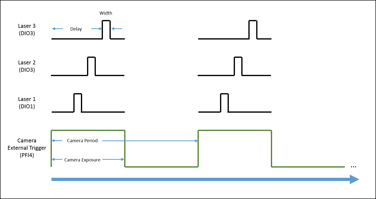
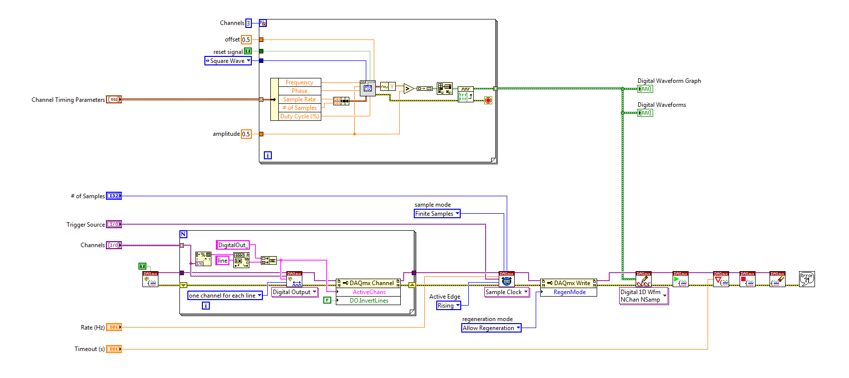
I'm trying to implement a system using a PCIe-6535 b connected to a high speed of SMB-2163 DIO. The system must be configured to work with a camera send a trigger (at the beginning of each show) to the PFI4 which in turn sends a single pulse on three digital output channels to lasers. Each output has its own specific deadline and the width. There is no counter on the SMB-2163, so I think I need to use Pulse Width Modulation (PWM). I saw this example and adapted to my system:
https://decibel.NI.com/content/docs/doc-8010
However, when the source to enter the DAQmx VI of sample clock is set to PFI4 (instead of the on-board clock) to receive input from the camera, changes in behaviour. The rate of sampling in the sample clock VI is ignored, and each element of the digital waveform is triggered. I need the sequence to complete each after trigger.
I am attaching a quick diagram of the sequence. Any suggestions on how I can get this kind of events triggered? (With the help of LabVIEW 2013)
Thank you
Mike
PLATES
The external signal must be configured as a trigger for digital startup rather than the sample clock. I do not think the 6535 redeclenchables supports digital output, so you don't have to restart the task after receipt of each trigger (something like this, however you can improve performance by committing to the task by using the task of control DAQmx before entering the loop).
Best regards
-
Hi all
I'm going through the phase of my small vi debugging and found an inconsistency that makes no sense. My goal is to generate a single TTL pulse as soon as I discovered a passage by zero of a sine wave. So, I generate a simple sine wave and send a logic true to the block which supposedly should initiate a TTL pulse generation. I first tested at 1 Hz sinusoidal and pulse TTL of ecu 1 Hz. I then put my sine funnction at 5 Hz, but I always only TTL signal of 1 Hz, instead of 5 Hz (1 pulse each time by resetting a sinusoid at 5 Hz).
Can anyone suggest where the problem is maybe?
Thank you in advance!
I think that your problem is easily explained by a single sentence in the help for the VI of passage to zero: "If wire you a waveform value or a dynamic data type value at the point of data entry, this VI evaluates only the first value of the input data."
-
single pulse width measurement
Hello
I'm trying to measure the duration of a single pulse using ctr0 on an SMU-6361.
The signal in the attachment Capture7.jpg, goes PFI 9, ctr0 door.
The problem is that the counter see ' s the front up and stops. The pulse width is not given as can be seen in the output (Capture8.jpg).
I get the same results by using Meas_Pulse_Width.vi example.
Is something wrong with my SMU-6361?
Oh, I think I know what it is.
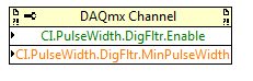
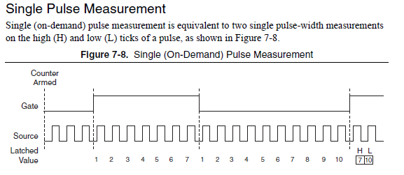
Change the task "pulse width" (a single pulse of height) instead of "Pulse" (the high and low time of a pulse repetition measures). Change the DAQmx Read to use Ctr > single sample > DBL (instead of pulse). Change the property filter node digital to use the corresponding properties of the "pulse width" (the filter is still necessary):
The task of the pulse was not period initially because you receive a series of noise pulse repetition (and so it was a very low period). With the filter, this time since the noise disappears now and the single pulse did not finish measuring the pulse (which requires a high and some time):
For the record, I agree that it is confusing that there is the "pulse" and "Pulse" measure and they do different things.
Best regards
-
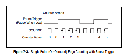
How to generate a single Point (On-Demand) edge counting with relaxing break
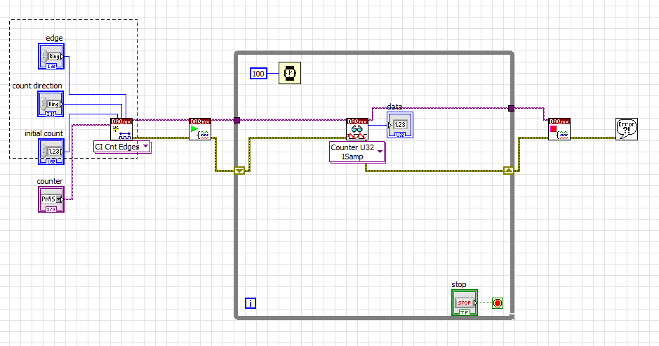
I have problem when creating a Labview program to generate a single Point (On-Demand) edge counting with relaxing break illustrated in FIGURE 1 below. I only know how to build counter edge without relaxing break and my program is illustrated in FIG. 2 and gaskets also. Should what changes I make on my program? The DAQ card that I use is 6259 PCI/USB.
FIG1. Single edge counting with break Point (on request)
Fig.2 my program to generate the edge without relaxing break
It is resolved
-
Hello!
My problem appeared when I tried to update my traditional NOR-DAQ legacy code to DAQmx.
I use 2 meter (meter 5 and 7 meter) on PCI-6602, to generate trains of pulses, as well as the lines of e/s digital port 0 (the form lines from 0 to 7). What I do in my request, it's that I'm starting to generate the pulse train on the output of 2 meters and after that I play with the State of digital lines.
Traditional, it was no problem to use the meters and digital lines at the same time, everything went perfectly, but in DAQmx, is not possible.
What's happening: I start generating train of pulses on the output of counters, no errors, but when I try to change the State of a line of digital port the generation of the pulse train is stopped. What happens when I start the task associated with the digital way.
My question is: is it possible to create a channel on digital lines without changing the channels created for meters?
Another thing that I managed to do with the panels 'Measurement and Automation Explorer' and Test for PCI-6602, is basically the same thing, I generate trains of pulses on the output of the 7 meter and try to start a job on the digital line, but I get an error:
"Error-200022 occurred in test Panel.
Possible reasons:
Measurements: Resource requested by this task has already been reserved by another task.
Device: Dev4
"Terminal: PFI8.On the contrary if I use the counter 0 or a counter 1 to generate trains of pulses I encounter the same problem.
What resources are used by 2 to 7 of the PCI-6602 card counters and the counters to 0 and 1 do not use?
Thanks in advance for any answer!
Ciprian
After doing some real tests on this device, I found that it is a normal behavior for the jury of 6602. This is because when you start a task digital all 32 lines are configured for digital i/o, so it replaces your meter operation. The article below the link explains a little more on this subject. You must start the digital task before the task of counter to use the features of both in your program.
2 meter and above will not work correctly when you perform digital i/o on NI 6601 or 6602
http://digital.NI.com/public.nsf/allkb/43F71527765EEC3886256E93006CD00C?OpenDocument
-
Sync to external trigger in conjunction with a nearest pulse frequency device fixed...
I am writing an application running a scan frame. One axis of the scanner runs at a fixed frequency. I use a scanner high speed 5105 to get the data. The slow axis of the scanner is controlled by a servo with an analog input. I have will probably use an M-series card for analog control, but can also go with a 6713 (output only) or another Board. Fixed frequency Analyzer provides a clock line, I want to use to drive the 5105. In addition, the analog card must be synchronized in this. The entire system should be able to accept a trigger external devices, as it starts scanning at the edge of clock on next line.
I'm not quite sure about what would be the best way to do it. External triggering from other devices will be an indeterminate pulse width, so I can not just use it as a portal for the line clock. I am reluctant to do it in software (IE via the detection of changes on a digital line) because I want to be reliable started the next clock pulse. I have taken into account things like a counter/timer with a relaxing break, but which could lead to drift between the narcotics control and frequency scanner fixed. It seems just more complex that I think it should be, and it feels like I'm missing a simple way to do it.
Any suggestions?
Hi cshl,.
Good to know - the 5105 has a duty cycle of tolerance of 45-55% (mentioned on the page of the form), so that is why you cannot change clock speed from 3 to 12 MHz on-the-fly (though if you make small incremental updates over time, it would be theoretically possible).
With the additional information in mind, you might want to try the following on the 5105:
Use the external trigger as a trigger of departure (arm of acquisition).
Use the line as a signal reference clock (with a position of 0 samples for reference ~ 7500 are after initiation).
The problem with this is that you will have to re - trigger on each line - 5105 has a 2.4 rearm us time (also mentioned in the page on record). If this is unacceptable, another way that I can think of is to use a clock to external reference in PLL internal clocks of the bezel to. If you can provide a stable, a clock accuracy 50 ppm which is synchronized with your scanner within reach, would solve the problem of drift over time without having to re - trigger on each line (only acquire data continuously). This clock frequency must be between 1 MHz and 20 MHz in steps of 1 MHz.
We have no Council can take in an external variable clock up to 12 MHz (on-the-fly), but if you wanted to compromise a little bit the 6115 can enjoy up to 10 MHz, and has no obligation to cycle to 45-55% so it's maybe interesting look in.
As far as AO goes, I assumed that the clock line is declared after the quick scanner has completed his turnaround (ideally you do not update the zone of OCCUPATION during the lead time). If you have a signal Analyzer that you can use instead probably easier. If not, our peripheral series M and X series (but not the series AO 67xx) offer reference clock feature so if you go with the idea of reference mentioned above clock it may be easier to simply PLL the clocks together. These cards in a PXI chassis or are they PCI form factor?
I don't know what you mean by the sticking point about the need for two triggers. I think the idea is that we use the external trigger to arm the 5105 and clock line to trigger each record. However, if you do not need to generate a pulse double based on the clock of your line then you can use counters to do (our counters are redeclenchables with time to rearm in the ns range).
Best regards
John
-
Generate trains of pulses overlap several
I need to generate signals up to 8 TTL pulse, train up to 500 Hz with heavy duty from 0 to 100% open and close the valves with an accuracy of timing of 5 microseconds. The pulse trains will be spread with equal delays and begin with a single trigger.
i.e.: If you have a period of 40ms and 8 valves, there will be a 5ms delay between each pulse train early. Each will have the same duty cycle and the period.
Trains of pulses must be performed simultaneously and stop when certain data criteria is met (the balance of the system state).
My Questions:
1 would be classified these as continuous or finite pulse trains?
2 do I need to use a counter/timer (or 2) for each train of pulses or can it be coupled with digital output?
3. what DAQ will have sufficient resources (counters/timers, DIO, etc.) to enable this work?
Thank you
1 continues. The idea of pulse trains finished is to predefine * precisely * how many cycles to generate. You will make assessments based on the software to decide whether to stop the pulse trains, but you will not be able to predict when this will happen in advance.
2. all things being equal (and it's not often), I could certainly do that with counters. You can easily reach the accuracy of your calendar and let the data acq hw do all the work. DIO can be an option, but it could prove to be a pain in the neck to set the output buffer to handle delays including and precision, you need.
3. I'd go with an oldie but goodie, the PCI-6602. It has 8 available counters, as well as a little extra DIO.
-Kevin P
-
5.6.1 MacBook early 2015 OS X 10.11.3 pages
Question: How can I easily format a series of "a line of questions / answers" (questions and answers on the same line.)
How to easily create a long series of a single line of questions and answers to the question aligning it on the left and the end of the response by aligning right?
For example
!. Type the short question on the left margin.
2. tab at the right margin.
3. type the answer with the end of the answer on the right margin.
Insert a right tab at the right margin.
Peter
-
How to set the output meter channel to generate a signal pulse using DAQ6008
Hello there I am generating a pulse signal of 100 Hz and a duty of 20% of the 6008 data acquisition cycle using visual studio 2013. I have code that needs to generate this but I'm not sure on how to set the channel output meter. When I run this NI MMAX and my vb error code indicates that the physical channel is not supported. I am a user of data acquisition were first and would appreciate any help offered.
If you look at the USB-6008/6009 User Guide and specifications, you will see that the counter in these devices cannot rely as edges of entry. It cannot generate a pulse.
Lynn
-
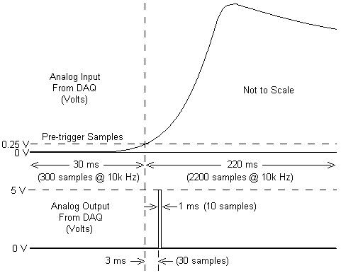
I am working with a combustion chamber and using a system of data acquisition (with the hardware OR SCB - 68) to read the pressure in the cylinder (such as analog voltage). I'm trying a pulse delayed, 1 millisecond to 5 volts of output once the pressure in the cylinder is high above 5 bar (which corresponds to an analogue voltage of 0.25 V). I would also like to record 30 ms samples before the trigger and 220 ms samples after the outbreak. The following image shows visually what I'm talking about.
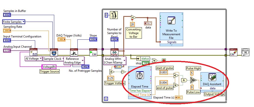
I created a LabVIEW VI (which is attached), but I keep running into 2 issues:
- When I run with samples finished after a period of time, I get error-200281which I don't quite understand.
- Using the Express VI 'Out of time' to keep time for the pulse I can not get a resolution of 1 millisecond, the pulse is not generated when I put the window between 0.003 and 0.004 seconds for high pulse (i.e. the resolution of 'Elapsed Time' seems to be too coarse).
I'm a beginner to LabVIEW sorry if my questions are trivial or my VI makes no sense, but I was stuck on this during more than a week. Any help would be greatly appreciated!
Thank you
Morgen
This isn't a good way to trigger a pulse.
Use a trigger DAQmx to send the pulse when your acquired signal exceeds 250 mV you specified.See this for DAQmx trigger:
-
generate trains of pulses of 5 kHz
Hello
I would like to generate digital impulses to 5 kHz oe less rate, any recommendation of material? better usb and budget type.
I have usb 6501, I try to work on this, maximum output is 1 kHz the best. Is it possible to above?
Appreciate any help here.
Kind regards
Simon
You can use each channel to generate the train of pulses at a different frequency at the same time, and generation of pulse stops immediately as soon as the task is stopped.
-
Generate/play digital Pulse - which one to use?
Hello
I use NEITHER cDAQ-9172 (with NI 9472 output module and input module (9421)) I am trying to generate a pulse, run it through a system (just a resistance at this point) and then read it in labview. I am in a position to generate the momentum without problem, but whenever I try to read it I get an error about the clock. Any suggestions?
Thank you
Looks like that I thought about it. I had the said clock as timed material, but my hardware was wired wrong. Once I corrected the connections it worked, so that must have been the problem.
Maybe you are looking for
-
components of taskbar scheduled
Somehow I lost the taskbar preview streams on my Windows 7 computer. I now have a box that appears identifying each program in the taskbar, but I more pictures I had originally. What I did and how can I cancel it?
-
I can't find drivers for my laptop... I can't find any information on this subject, in the forum too... S/N: CNF7112W9L P/N: GF656EA HP Pavilion dv6315ea
-
The upgrade of Windows 10 blocking does not work
I am training remotely for my University and am unable to upgrade to windows 10 since it is not compatible with several programs that we use. I followed all the instructions to remove the automatic updates, but he's back. The only suggestion I have
-
How can I me ad block installed on my pc?
How can I me ad block installed on my pc I've had now his party?
-
I recently installed Cubase as part of my university course. The sound works well in Cubase, but now whenever a system of sound or any other playback sound is indicated I get white noise. The volume mixer seems functional and green bars seem to respo